Electronic Production
Individual Assignment
make an in-circuit programmer that includes a microcontroller: extra credit: customize the design mill and stuff the PCB test it to verify that it works
Group Assignment
characterize the design rules for your in-house PCB production process
Group Assignment
Here is a link for our group assignment
Individual Assignment
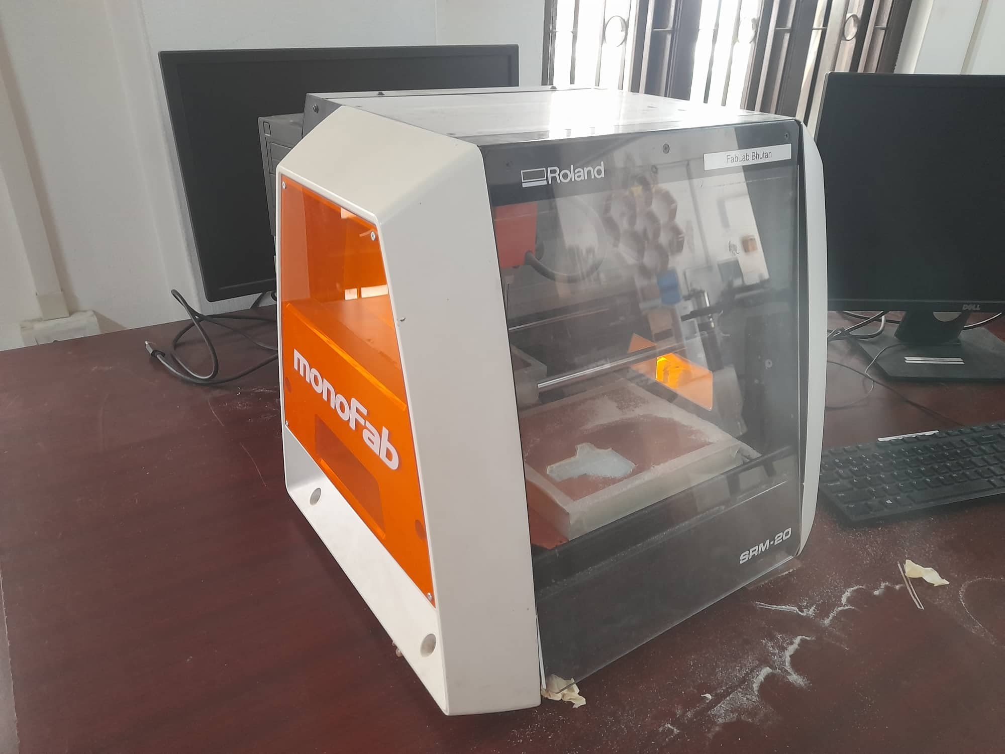
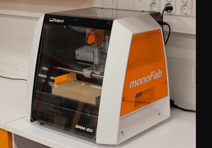
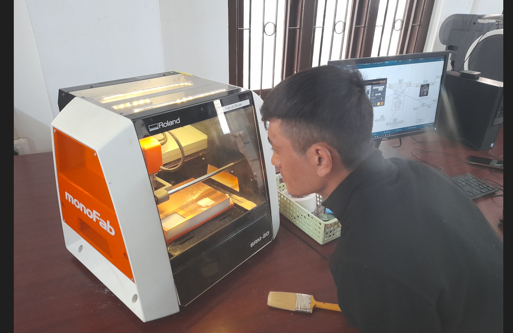
For this week assignment i learned about SRM-20. SRM-20 is used for milling the PCB.
making an in-circuit programer
To make my fab ISP I reffered to Brian's page.
From Brian's page i downloaded the trace and border or outline from brian's page
Tools required for making fabISP
1. PCB Board- The PCB we used is for SMD(surface mount device). It is an electronic device on which the electronic components are mounted or placed directly onto the surface of PCB.
2. Double sided tape- For making PCB stble on the bed inside SRM-20
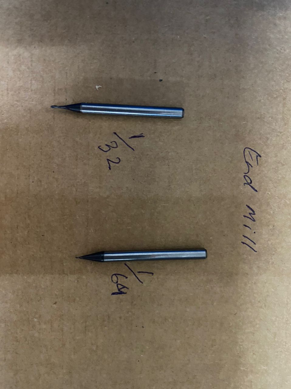
3. End mills
1/32" - it is used to mill the edge of the board
1/64" - It is used to mill the traces on the board
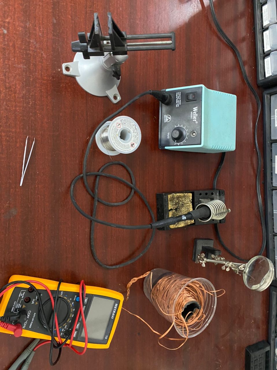
4. Magnifying glass.
5. Fumes extractor
6. Soldering Iron
7. Soldering lead
8. Stand- To hold the board while soldering
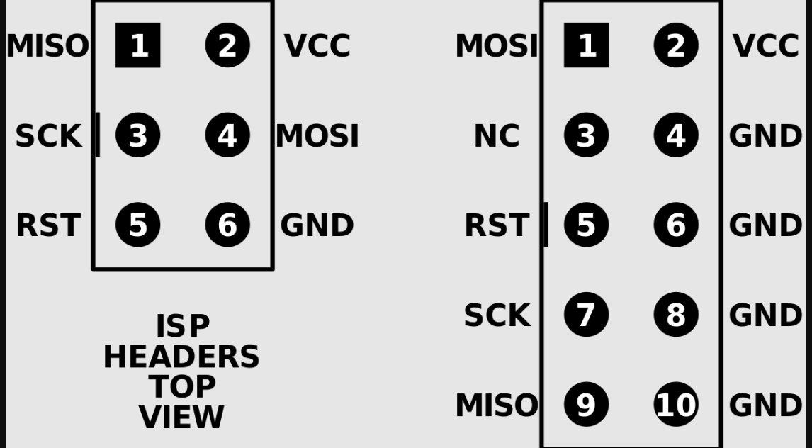
ISP(In-system programming
It is also call in-circuit programming. USBtiny is a software implemented with low speed protocol which is used to program Attiny microcontroller. My USBTINY was designed by our tutor Mr.Suhas. Milling the board and soldering the devices was done by me. Than I programmed the attiny45 microcontroller. To program on USBtiny we used Linux OS. It can be done through windows also. After ISP is programmed than we can program echo hello board through it. I have programmed using Atmel
Roland SRM-20(milling machine)
The SRM-20 was designed with a number of technological advancements that include a touch-button VPanel controller to regulate feed rate, spindle speed and milling on a complete X, Y, Z axes, and a new independent collet system that allows for faster setting of the Z-axis base point and quick tool changes.
Feautres of SRM-20
Here is a link for features and specification of SRM-20
PCB Fabrication
For my FabISP i used Brian's design which is available in fabacademy
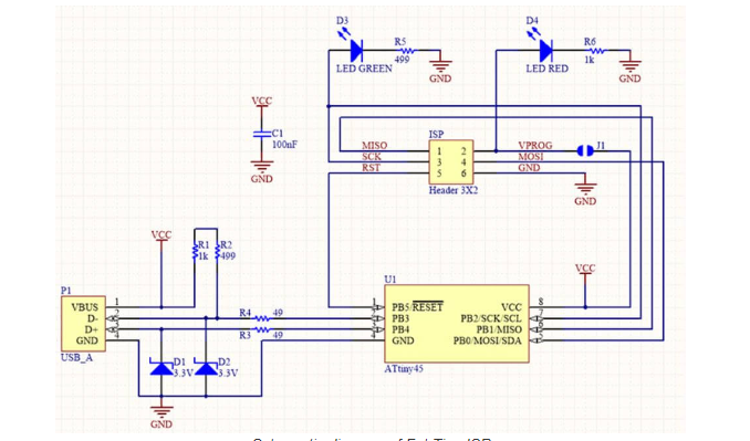
Schemantic design of ISP
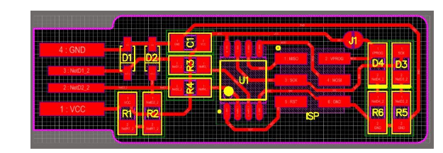
Board diagram of ISP
I downloaded the trace and outline in .png format.


Conveerting PNG to RML(redline markup language) format using mit mods
The machine readable format is RML, so to convert PNG to RML i used mit mods
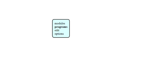
I open the mit mods page and than i right click -> click on program -> and open server program
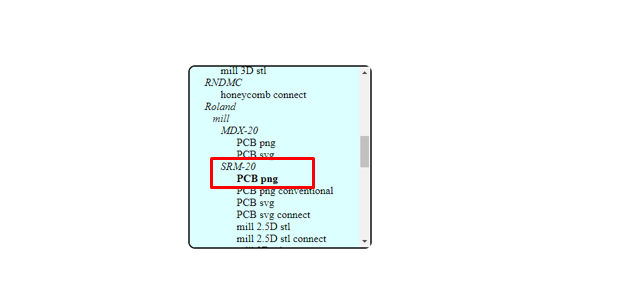
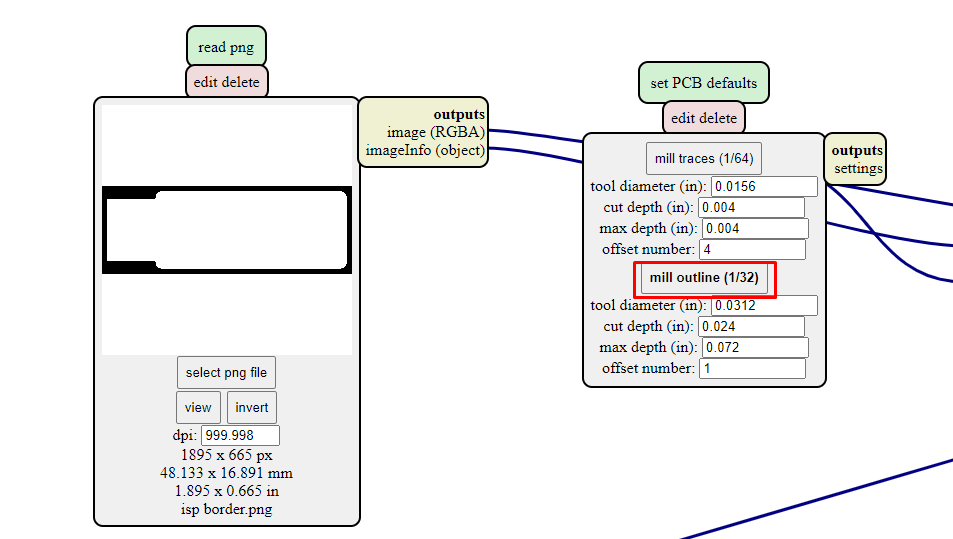
select the machine SRM-20 and PCB png as shown in pic below
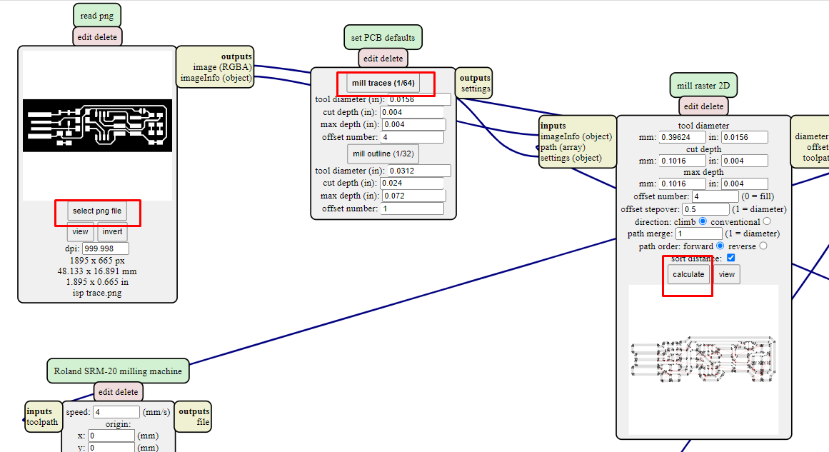
Here is where we can convert PNG files to RML. I have uploaded the files seperately to generate RML files for bth traces and outline
Select the trace file and select 1/64" mill and calculate
delete the pre-existing module and create module. to add module right click and open server module.
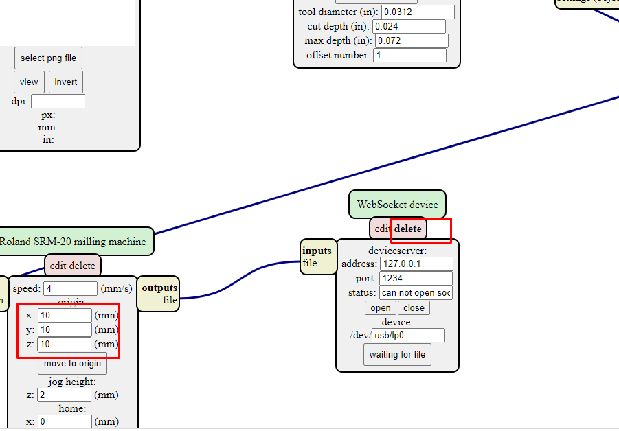
Save the file and connect input file with output file
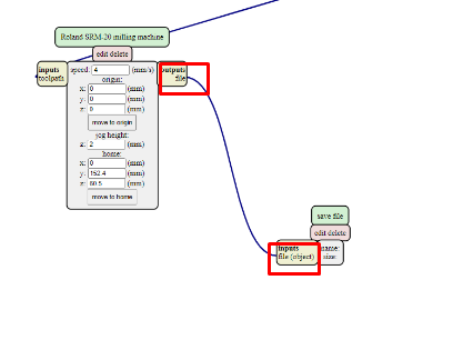
Now click on calculate to generate RML file. RML file will be automatically downloaded
For generate RML file for outline we have to foolow same steps except on choosing mill. for outline we have to choose 1/32" mill
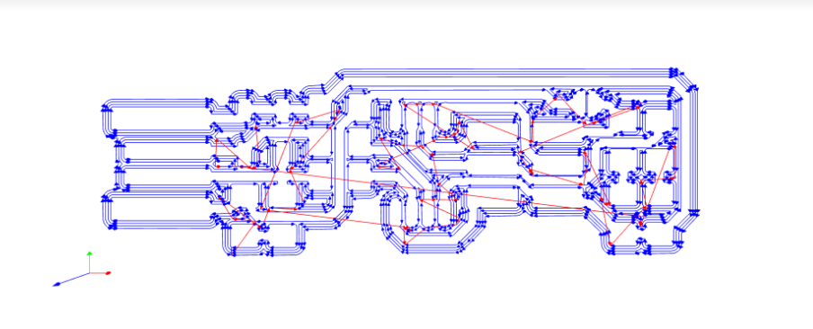
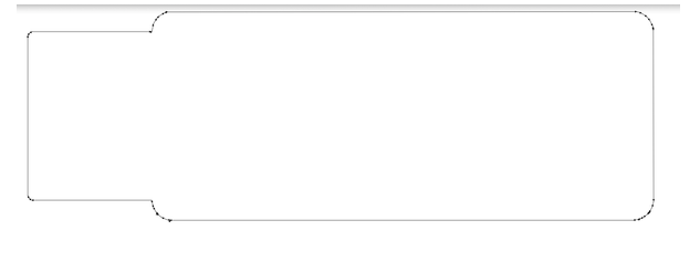
Toolpath for ISP trace and outline
Milling the Board using V-panel
1. Open Vpanel software to mill in SRM-20
2. Insert th 1/64" end mill to mill the trace in SRM-20
3. Set X,Y and Z-axis cordinate. Its for setting orgin and zeroing
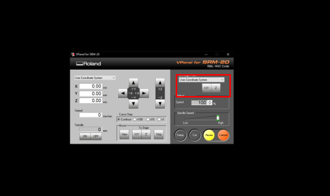
After setting X,Y and Z click on cut. delete the existing file and add the trace. than click on output. It will start milling the trace
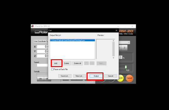
To mill the outline we need to change the end mill to 1/32". X and Y cordinate should not be changed but Z-axis has to be done zeroing. Than add the RML file for outline and click on cut.
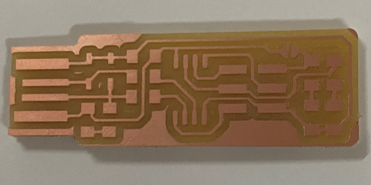
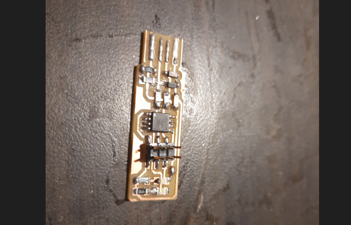
My board after milling
Soldering the ISP
Components for ISP
1. 1x ATtiny45 or ATtiny85
2. 2x 1kΩ resistors
3. 2x 499Ω resistors
4. 2x 49Ω resistors
5. 2x 3.3v zener diodes
6. 1x red LED
7. 1x green LED
8. 1x 100nF capacitor
9. 1x 2x3 pin header
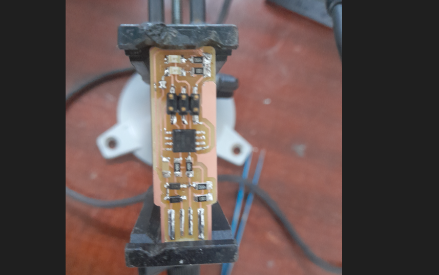
My fabISP after completing soldering
Programming on fabISP through Linux(Ubuntu)
after complrting with soldering i need to program the ISP using ISP programmer
Steps to program ISP
All steps are available in Brian's ISP. Download the Firmware sourse code and unzip to install the firmware
Open terminal to direct to makefile and open the makefile using command "cd"
In make file change PROGRAMMER ?= usbtiny as PROGRAMMER ?= atmelice_isp.
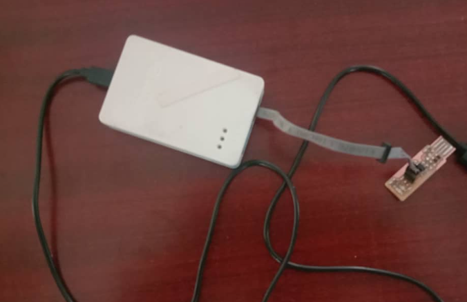
Connect the fabricated chip and atmelice
Than connect fabricated chip and atmelice to usb port of a PC
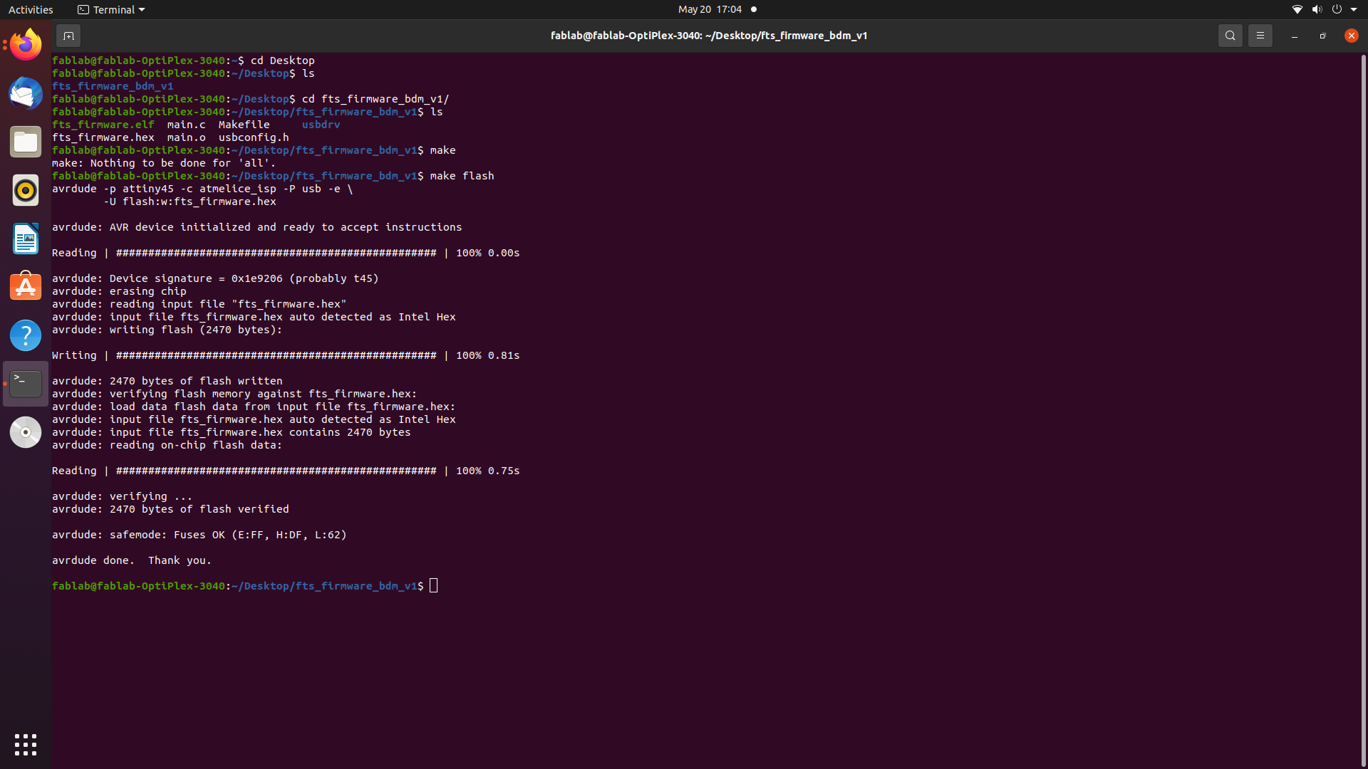
After completing with connection type these commands in termianl
1. Make
2. Make Flash
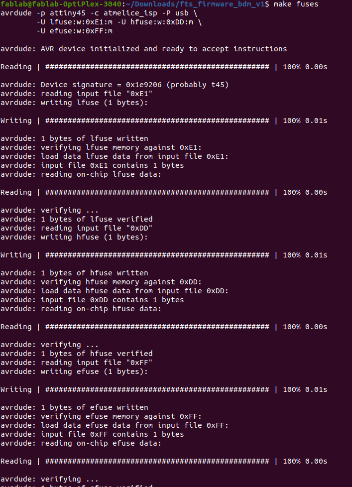
3. Make Fuses
Command to check whether my ISP has been programmed and recognized as ISP programmer
1. lsusb
After the usbtiny is programmed we need to disable the ability to program again. So i used "make rstdisbl" command on terminal to disable