Network and communication
Network and Communication
Group Assignment
Send a message between two project
Individual Assignment
design, build, and connect wired or wireless node(s) with network or bus addresses
Group Assignment
Link for group Assignment
Netwwork and Communication
Networking is the practice of transporting and exchanging data on a shared medium in an information system.
Communication also means same. It means sending and receiving information.
Image source google
Wired/wireless networking
Wired communication
A wired network connection is a configuration that involves cables which establish a connection between two or more devices on a network. Transmission of data are done over a wire based communication
Eg. wifi, bluetooth, radio frequency
Wireless network
A wireless communication is type of data communication that is performed wirelessly. The connecting and communicating between two or more devices using a wireless signal through wireless communication technologies and devices.
Difference between wired and wireless network
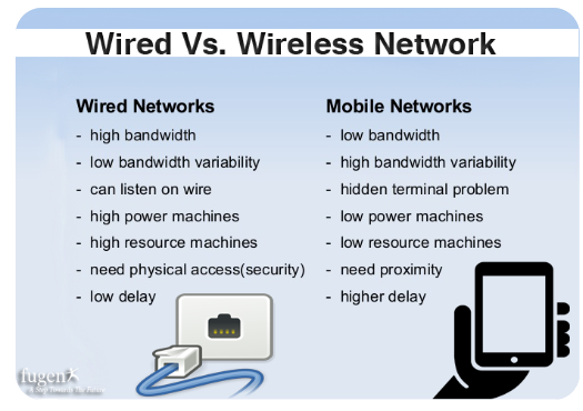
Image source google
Synchronous network
In synchronous network the data is transmitted and received at same time. data is simultaneously transmitted in both direction. Synchronization is accomplish with a signal clock.
Asynchronous network
An asynchronous netork is opposite of synchronous network. It does not use a single clock to transmit or receive data and the data flows in only one direction at a time.
Communication Protocol
Communication protocol is a set rules for a communication system to transmit data by any type of variation.
There are two types of communication protocol
1. Inter system protocol
2. Intra system protocol
Inter System Protocol
Inter System protocols are used to communiccate between two different devices.
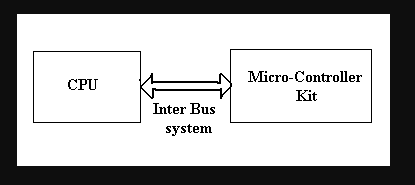
Image source google
Types of inter system communication protocol
1. USB(Universal Serial Bus) protocol: It was first created and introduced in 1996. It is a uniform cable ad connector that could be used across a multitude od different device
2. UART Communication Protocol: UART is a hardware communication protocol that uses asychronous serial communiction with configurable speed. There is no clock signal to synchronous the output bits from transmitting device going to the receiving end.
3. USART(Universal Synchronous/Asynchronous receiver/Transmitter) Communication Protocol: is a microchip that facilitates communication through a computer serial port using the RS-232C protcol.
Intra system protocol
The intra system protocol establish communication between components within the circuit board.
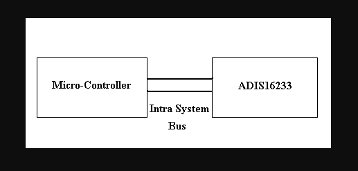
Image source google
The different catagories of intra system protocol mainly includes
1. I2C protocol
2. SPI protocol
3. CAN protocol
I2C communication protocol
>I2C stands for the inter-integrated circuit and it requires only two wires connecting all peripherals to the microcontroller. I2C requires two wires SDA (serial data line) and SCL (serial clock line) to carry information between devices. It is a master to a slave communication protocol. Each slave has a unique address. The master device sends the address of the target slave device and reads/writes the flag. The address matches any slave device that the device is ON, the remaining slave devices are disabled mode. Once the address is match communication proceed between the master and that slave device and transmitting and receiving the data. The transmitter sends 8-bit data, the receiver replies 1-bit of acknowledgment. When the communication is completed master issues the stop condition. The I2C bus was developed by Philips Semiconductors. Its original purpose is to provide an easy way to connect CPU to peripherals chips. Peripheral devices in embedded systems are often connected to the microcontroller as memory-mapped devices. I2C requires only two wires for connecting all the peripherals to the microcontroller. These active wires, called SDA and SCL, are both bidirectional. SDA line is a serial data line and the SCA line is a serial clock line.
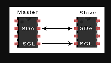
Image source google
I2C uses only 2 bi-directional open drain lines for data communication. It is SDA and SCL
1. SDA(Serial Data)- Trnsfers data through pin
2. SCL(Serial Clock)- It carried clock signal
SPI protocol
SPI stands for the serial peripheral interface. It is one of the serial communication protocol developed by Motorola. Sometimes SPI protocol is also called a 4-wire protocol. It requires four wires MOSI, MISO, SS, and SCLK.SPI protocol used to communicate the master and slave devices. The master first configures the clock using a frequency. The master then selects the particular slave device for communication by pulling the chip select button. That particular device is selected and starts the communication between the master and that particular slave. The master selects only one slave at a time. It is a full-duplex communication protocol. Not limited to 8-bit words in the case of bit transferring.
CAN protocol
CAN stands for the controller area network. It is a serial communication protocol. It requires two wires CAN High (H+) and CAN low (H-). It was developed by the Robert bosh company in 1985 for in-vehicle networks. It is based on a message-oriented transmission protocol.
Diffenences between the intra system protocols
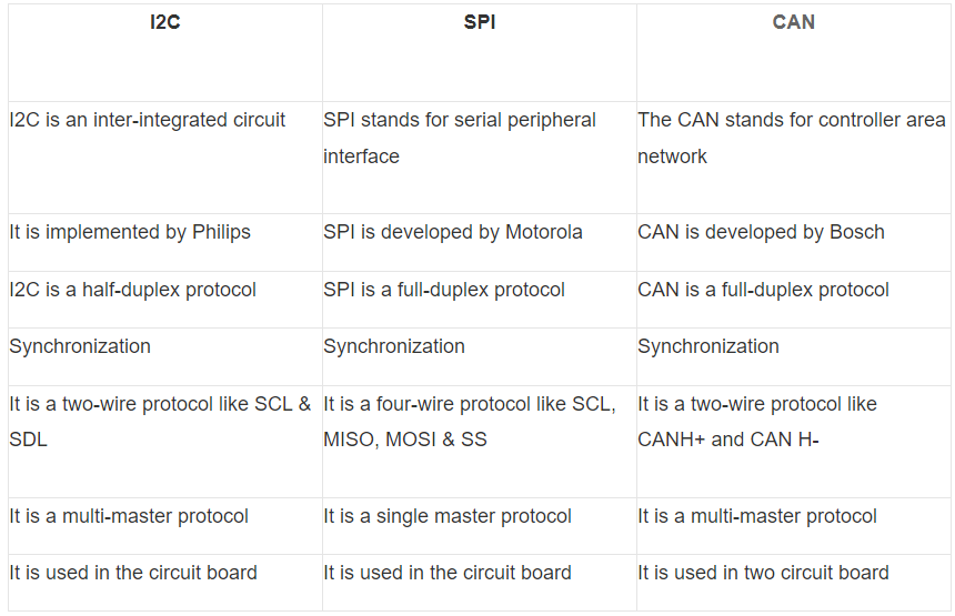
Image source google
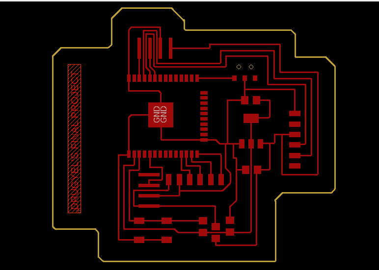
Designing Board
I have used same board which i used for my input and output week.
Connecting ESP to wifi
I am using ESP32 microcontroller so firstly i need to connect ESP32 to wifi
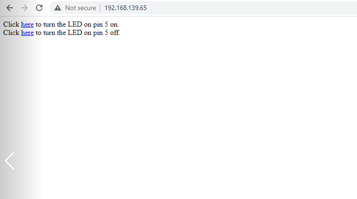
To connect ESP to wifi, I open Arduino IDE software and go to file, than example, wifi and click on simple wifi server
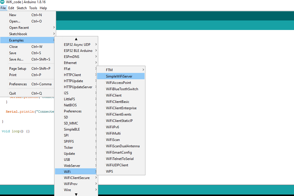
than i enter "SSID and password" of the network i wanted to connect to.
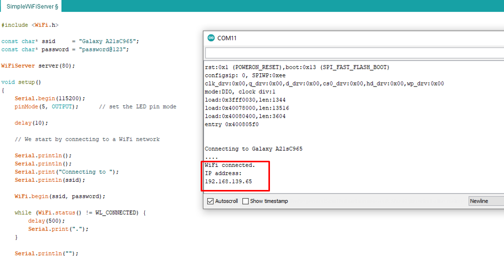
After giving SSID and password wait till the connection is completed
ESP32 is connected to wifi
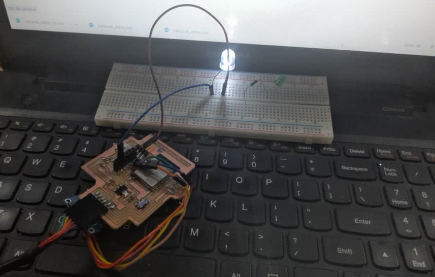
Programming ESP32 microcontroller
I have used FTDI cable to program my ESP32 microcontroller from Arduino_IDE. AND i have connected LED on a breadboard
I use simple code to blink LED from example given in Arduino_IDE
Than i compile and upload the code. than click on a serial monitor and copy the IP address and open it in web.