Input device
Group Assignment
probe an input device's analog levels and digital signals
Individual Assignment
measure something: add a sensor to a microcontroller board
that you have designed and read it
Group Assignment
Here is a lin for our group assignment
Individual Assignment
Input Device
Sensors are generally allude as info gadgets. Sensors like phototransistor and photograph diode that identifies how much light, temperature sensors, pressure sensors, stickiness sensors, liquid sensors, and so forth.
An info gadget responds to switches in the climate up it and delivered an electrical sign for handling to an electronic circuit. It is for the most part assembled into 2 classifications; Active and Passive gadgets.
Acive input gadgets produced a voltage because of changes around its current circumstance. The accompanying info gadgets needn't bother with a different power supply.
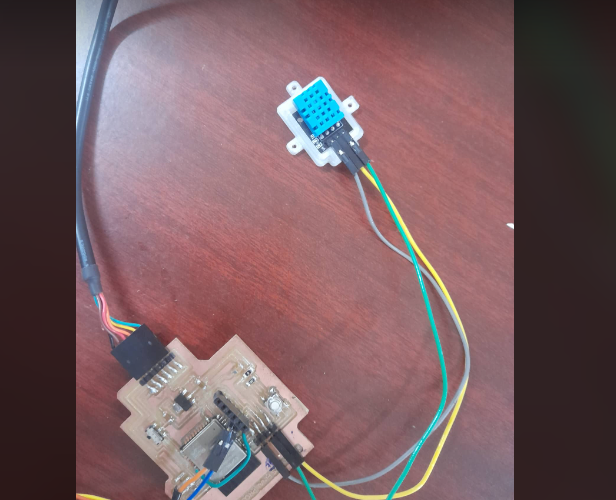
I used DHT11 as an input device
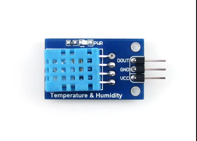
DHT11
This instructional exercise takes care of the low expense DHT11 temperature and humidity sensors. These sensors are exceptionally fundamental and slow, however are perfect for specialists who believe that should do a few essential information logging. The DHT11 sensors are made of two sections, a capacitive humidity sensor and a thermistor. There is likewise an extremely essential chip inside that does a simple to computerized transformation and lets out a computerized signal with the temperature and humidity. The advanced sign is genuinely simple to peruse utilizing any microcontroller.
Specification of DHT11
1. Low cost
2. 3 to 5V power and I/O
3. 2.5mA max current use while requesting data
4. Good for 20-80% humidity with 5% accuracy
5. Good for 0-50 degree celcus reading
6. Not more than 1Hz sampling rate
7. Body size 15.5mm * 12mm* 5.5mm
8. 4 pins with 0.1" spacing
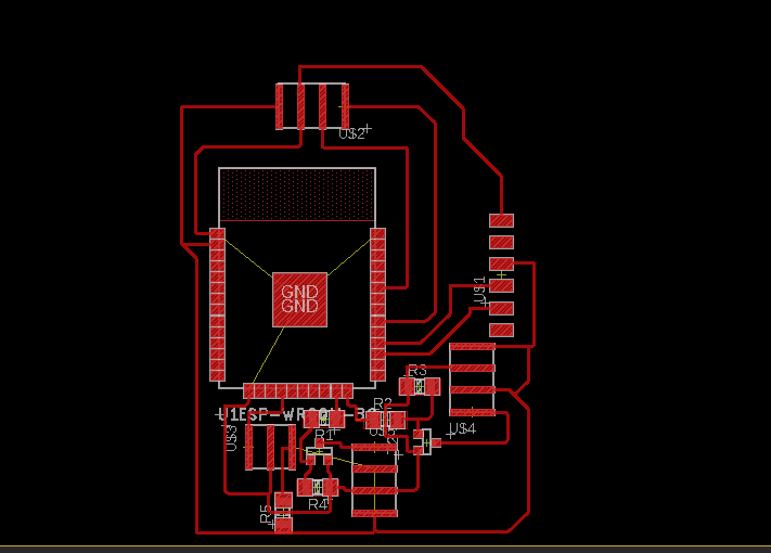
Board Design and soldering
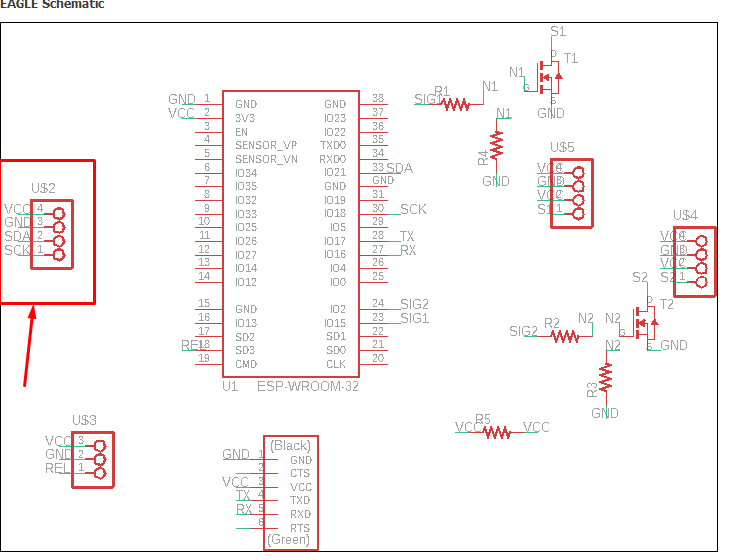
I used my final project board for my input week. So for my final project i use ESP32 microcontroller.
Components for my board
1. ESP32 microcontroller
2. Slide switch
3. Tact switch
4. Capacitor 1uf, 10uf and 0.1uf
5. 3.3v regulator
6. FTDI connector
7. 4 header pin
8. Resistor 10k ohm
9. I2C pin
Schementic and board design
For my input assignment i am using my same board that i have used for output.
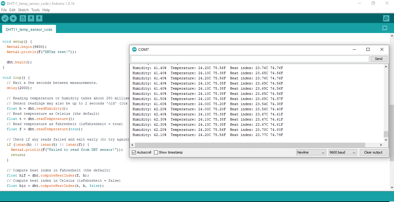
I connect all my dht11 sensor to my board using jumper wire. I programed through ftdi connector
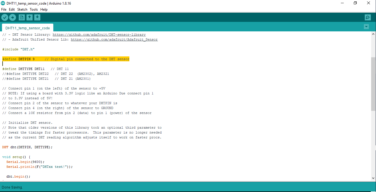
Programming to read sensor
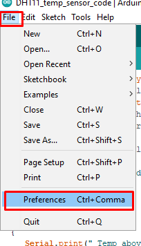
Open arduino IDE, go to file, and preferences
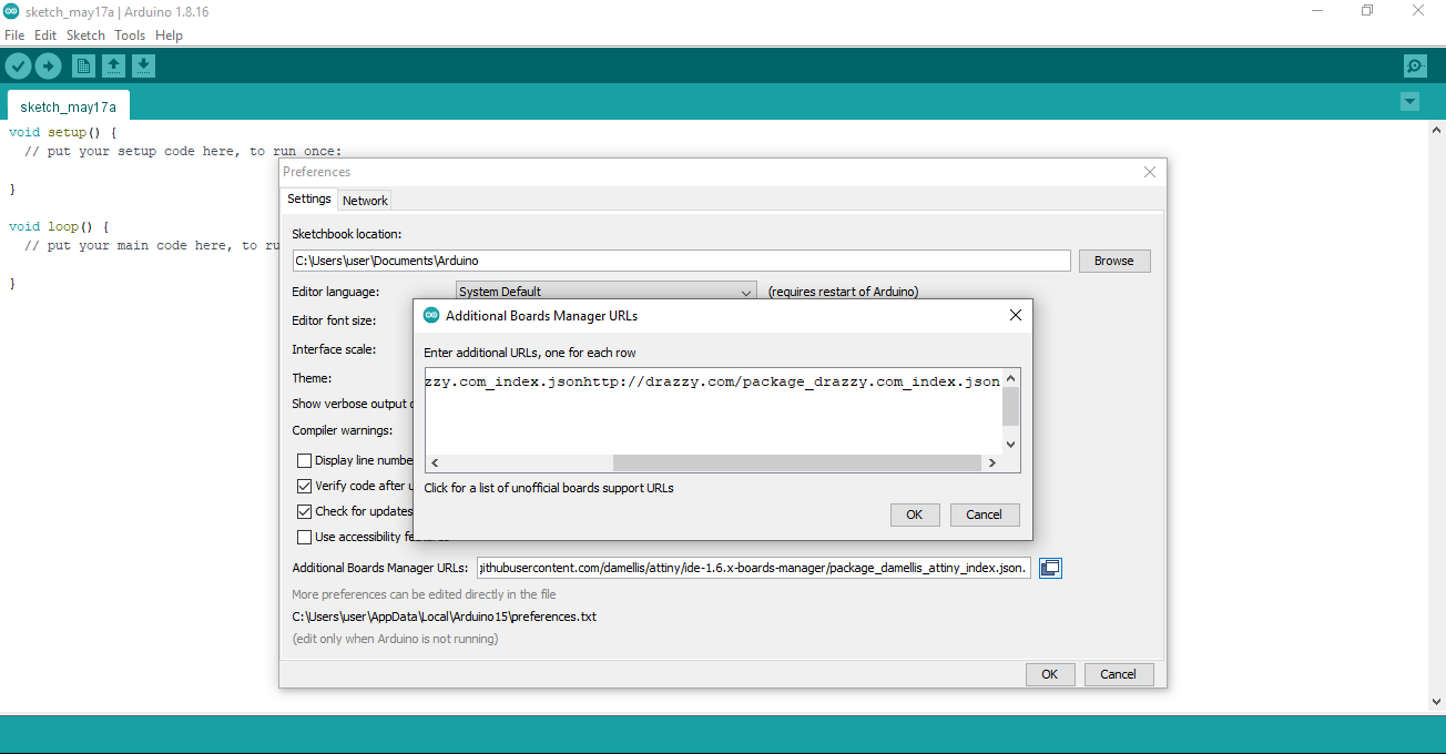
Copy and paste the link "https://dl.espressif.com/dl/package_esp32_index.json" in Additional Board Manager URLs as given below in picture
Than go to tools, Board and board manager
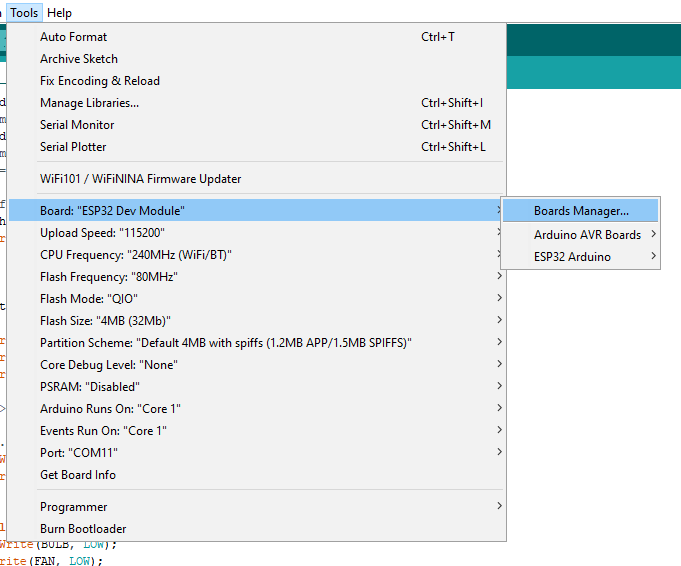
Than type "ESP32" and install
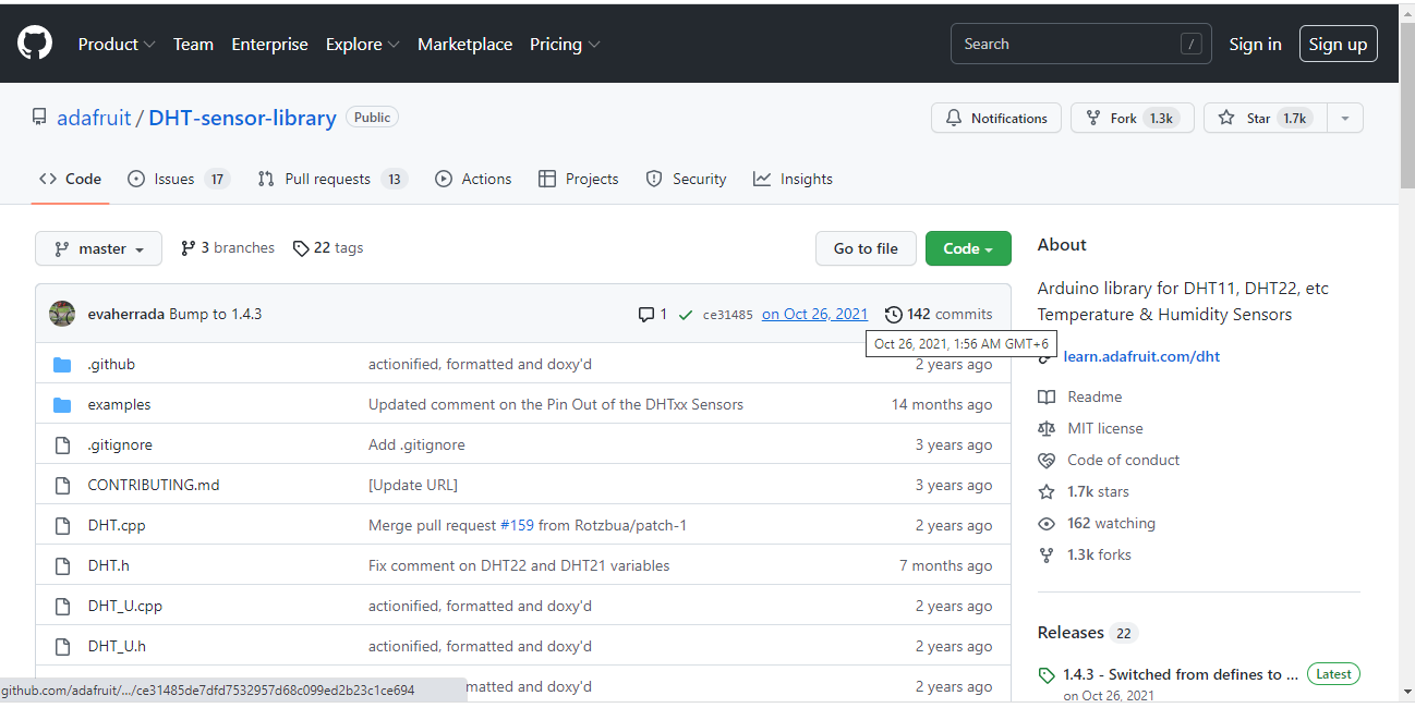
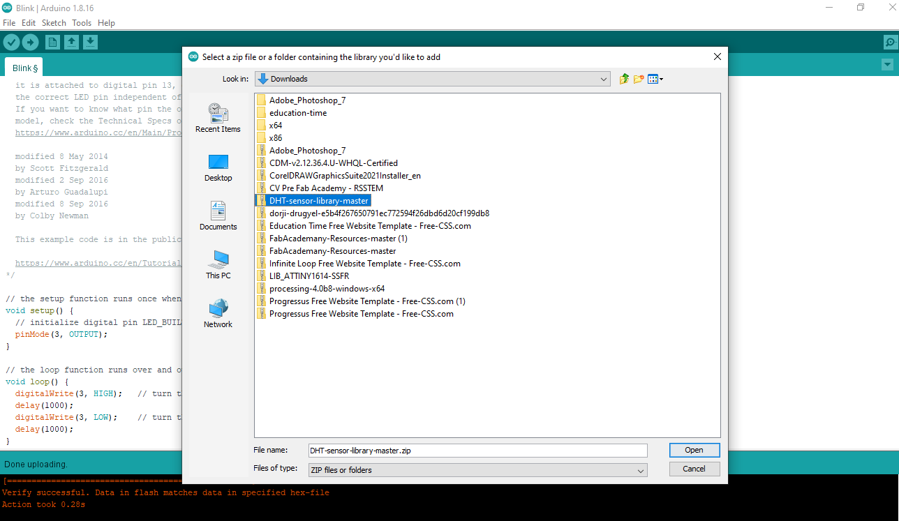
Download the DHT11 library and extract the library to open in arduino IDE
Link to download DHT11 library
Make data pin according to the requirement