Networking and Communications
Group assignment
- Send a message between two projects
The idea!
Considering the boards that each of us had working at the time and our programming level we decided to use the Serial UART (Universal Asynchronous Receiver-Transmitter) bus, of the AtMega328 microprocessor of Dani's board and communicate it with the AtTiny45 Isma's ambient light sensor. The main goal was to connect to projects and make one collect ambient data and the other reacts accordingly.
Sensor side code
For this I only modify the existing code that was measuring the raw value from the LDR and approximating the lumens it represents, and compare it with some threshold values, to also send this data over serial port with a predefined 'character code'
| ASCII Character | Meaning |
|---|---|
| 'a' | Based on the ambient light the sensor determines that more light is needed |
| 'd' | There is too much light or is below the night threshold, light is not needed. |
The data is sended via serial port at 9600baud, by following the table listed before to 'encode' the meaning. you can see more on the code file.
See the code DownloadLED side code
For this I modified the previous code I had to turn on the RGB Led and addapt it to respond to Isma's LDR.
The led is going to respond on and off. The data sent via serial port at 9600 baud, will have this conditions:
if "a" is received, the led will to turn on, indicating that light is needed.
If "d" is received, the led will turn off, indicating light is not needed.
| Character | Meaning |
|---|---|
| 'a' | The led will turn on |
| 'd' | The led will turn off |
Networking Working!
You can see the two boards connected and communicating with each other. When my hand covers the light sensor the light is not needed and the LED on Dani's (white) board is turned off when the sensor uncovered the light needed code is sent and the led turn on.
The 'main' board (white) is powered via the FTDI adapter and later USB connection to the computer. Only four wires are needed, 5volts, GND Tx and Rx. The sensor board recieves power from the 'main' board and sends the light data back.
Jeffery Naranjo, Send a message between two projects
In this week's assignment, I had to work on my own, because I'm taking the course virtuallySerial Communication using, ATtiny 44 turning on a led on the ATtiny44
Two ATtiny44s were connected by using the rx tx pins, when the button is pressed, the master pcb board sends a character to the slave pcb board, thus turning on the led integrated in the pcb board. For this assignment I will perform the communication of two pcb boards with the ATtiny44 controller, For this, the sender board is connected to the ATtiny45 programmer, the sender feeds the second receiver board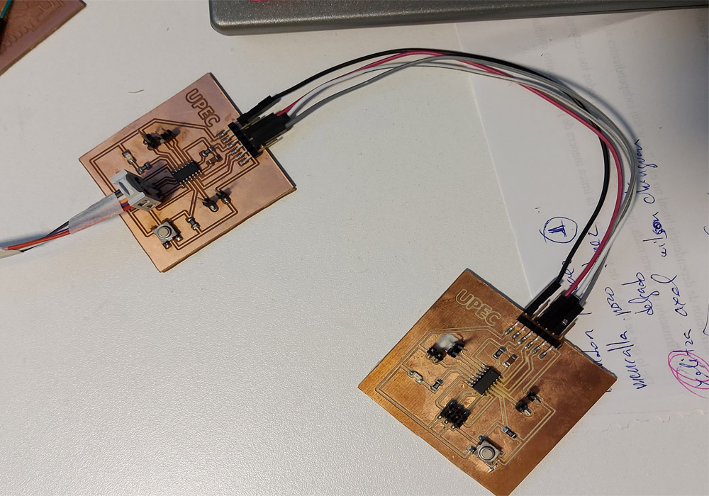 |
 |
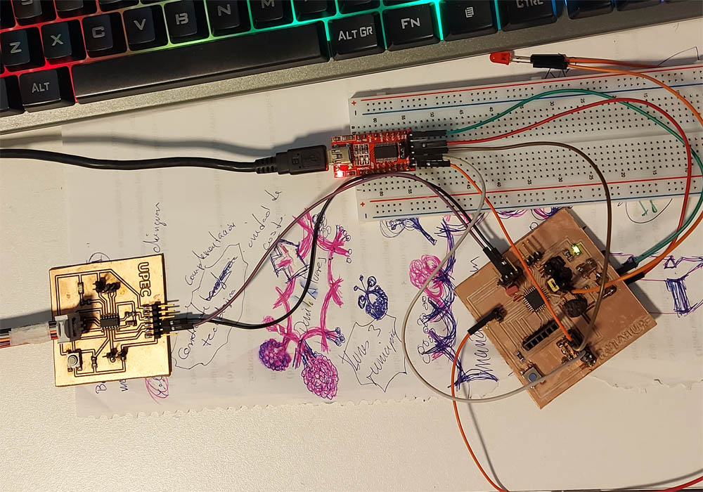
Serial Communication using, ATtiny 44 sending a character through a button to Atmega328p
The ATtiny 44 was configured as a sender, when pressing the button a character will be sent to the Atmega 328p receiver, when checking the received character we will light a led, to verify the shipment we can do it through a serial monitor, because our 328p pcb board is connected to the computer through the FTDI module. For communication between the ATtiny44 controller and the Atmega328p, we put the first connected to the ATtiny45 programmer as a power supply and the Atmega328p controller to the FTDI module.
 |
 |