Output Devices
Types of Output Devices
There are various types of output devices that exist. They can be communicated with in thre main ways: a PWM signal, a digital signal, and over some sort of communication protocol. These output devices range from the most simple being an LED to far more complex devices such as OLED screens. The way these output devices worked are usually rather complicated even LEDs which work by emitting photons by passing an electrical current through a semiconductor. Or DC motors which use induction to rotate. Regardless the components are incredibly useful in allowing our devices to do more than just gather information and actually having a useful way to relay that information else than over Serial.
There are various types of output devices that exist. They can be communicated with in thre main ways: a PWM signal, a digital signal, and over some sort of communication protocol. These output devices range from the most simple being an LED to far more complex devices such as OLED screens. The way these output devices worked are usually rather complicated even LEDs which work by emitting photons by passing an electrical current through a semiconductor. Or DC motors which use induction to rotate. Regardless the components are incredibly useful in allowing our devices to do more than just gather information and actually having a useful way to relay that information else than over Serial.
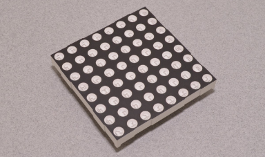 8 by 8 LED Matrix
.png) LCD Screen
LCD Screen
.png) OLED Screen
OLED Screen
Group Portion
This week the group portion of the project involved us learning about various output devices and how to communicate with them. We then tested out as a group the effect of voltage and current on a DC motor. We achieved this by hooking up the DC motor to a power supply unit and checking the minimal voltage needed to start it and the effect of increasing the voltage further and how the current changed accordingly. In addition we tried holding the motor while the power was on and saw the effect with the current spiking in response. Finally we noticed how when we rotated the DC motor manually we would get a current, this is how we make most electricity. When the PSU was set to 5 volts the reading was 0.1 amps but when the shaft was held the current spiked to 0.6 amps.
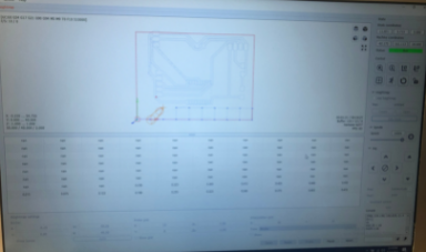
The second topic we discussed was that of PWM or pulse width modulation. The microcontrollers can only emit a HIGH or LOW signal, and no in between. However using PWM we can mimick and in between signal by changing the rate the signal is sent. One can use the analog write command with a value between 0 and 255 to determine what is called the duty cycle. A 50% duty cycle would mean that half the time it is on and half off, 75% would be 3/4 time on 1/4 off and so forth. This allows us to mimick sending lower voltages allowing us to change the brightness on an LED. We did this and looked at the PWM signal on an oscilloscope.
This week the group portion of the project involved us learning about various output devices and how to communicate with them. We then tested out as a group the effect of voltage and current on a DC motor. We achieved this by hooking up the DC motor to a power supply unit and checking the minimal voltage needed to start it and the effect of increasing the voltage further and how the current changed accordingly. In addition we tried holding the motor while the power was on and saw the effect with the current spiking in response. Finally we noticed how when we rotated the DC motor manually we would get a current, this is how we make most electricity. When the PSU was set to 5 volts the reading was 0.1 amps but when the shaft was held the current spiked to 0.6 amps.
The second topic we discussed was that of PWM or pulse width modulation. The microcontrollers can only emit a HIGH or LOW signal, and no in between. However using PWM we can mimick and in between signal by changing the rate the signal is sent. One can use the analog write command with a value between 0 and 255 to determine what is called the duty cycle. A 50% duty cycle would mean that half the time it is on and half off, 75% would be 3/4 time on 1/4 off and so forth. This allows us to mimick sending lower voltages allowing us to change the brightness on an LED. We did this and looked at the PWM signal on an oscilloscope.
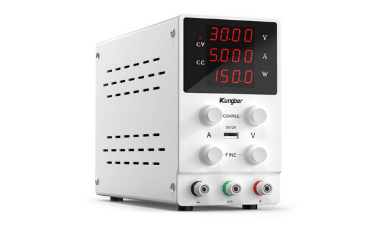 PSU Used
.png) Program for PWM led
Program for PWM led
.png) PWM oscilloscope
PWM oscilloscope
Designing and Fabricating
For this weeks project I actually used my messed up board from last week that I connected the microcontroller to the few pins that do no support analog read. However for this week I was planning on hooking up a speaker and an LCD screen anyways so that was not nesseccary to have. The process is the same as in every other week using KiCAD connected LCD to attiny 3216 using I2C then connected speaker pins to any arbritrary digital pins. I then assigned the footprints, went to PCB view, and using FreeRouter routed the traces. I then exported it as a GERBER to FlatCAM and brought in the NC file to Candle where I milled it using my mill with a 1/64 ball nose working on the first time since I can make a height map unlike the 3k$ Roland. Soldered the board as usualt with solder paste and tested it with mutltimeter. (This section might as well be copy and pasted for every week).
For this weeks project I actually used my messed up board from last week that I connected the microcontroller to the few pins that do no support analog read. However for this week I was planning on hooking up a speaker and an LCD screen anyways so that was not nesseccary to have. The process is the same as in every other week using KiCAD connected LCD to attiny 3216 using I2C then connected speaker pins to any arbritrary digital pins. I then assigned the footprints, went to PCB view, and using FreeRouter routed the traces. I then exported it as a GERBER to FlatCAM and brought in the NC file to Candle where I milled it using my mill with a 1/64 ball nose working on the first time since I can make a height map unlike the 3k$ Roland. Soldered the board as usualt with solder paste and tested it with mutltimeter. (This section might as well be copy and pasted for every week).
 Heightmap on FlatCAM
.png) Milling the Board
Milling the Board
.png) KiCAD PCB View
KiCAD PCB View
Programming
Up to this point I ran into no significant problems, and even in the programming else than some minor inconvenience due to my programmer just being on a breadboard so needed be be jiggled a bit, there were no other significant problems the arised. (Yes this is me writing for the criteria problems encountered there were none unless you want me to lie then this is it).
From here it was simple I plugged in everything accordingly and tested out the components. Started with testing the LCD with a simple "Hello World" and then did a quick test with the passive speaker. The passive speaker does not have a built in oscillator like the active buzzer, so using the tone function can change its sounds frequency. To program the buzzer I simply used the tone command and the frequency, and for the LCD I used the I2C LCD library since the LCD is hooked up over I2C ofcouirse remembering when designing to include the needed pull up resistors.
Now this project was pretty boring, so I spiced it up a bit and modified some code from the internet of soemone who is actually musically talented, unlike me, for there Mario song using the buzzer. I then make it so the LCD screen would say which mario song was playing at the time. Small neat project.
Music Code Stolen from this guy: https://www.hackster.io/techarea98/super-mario-theme-song-with-piezo-buzzer-and-arduino-2cc461
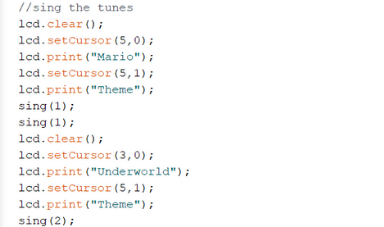 Void Loop from Function
.png) LCD Test
LCD Test
.png) Buzzer Test
Buzzer Test
Click Here to Download all the files from these projects!