Embedded Progamming
What are Micrcontrollers?
A microcontroller or MCU works very simmilar to a miniature computer having many of the same parts including RAM, a CPU, I/O ports, interrupt controls, timers, and so forth. However unlike computers they are are far more compact, and cannot have their internals replaced. For a brief run down, a CPU is the central processing unit where everything gets executed. In the CPU there are registrars which will store small amount of information and the ALU, artithmetic and logic unit, which will run calculations with information in registrers. This information comes from RAM or random access memory which will store information likely to be needed by the CPU for fast transfer to the CPU when needed. However all the information itself is stored on ROM or read only memory which will store the binaries themselves to be read by the RAM.
In addition due to their simplicity, they are significantly weaker than a computer, and typically not capable of running multiple processes at the same time. For this reason when we program most microcontrollers the only thing we program the controller with is just a hex file, which is the binary of the executable itself, and nothing more. Unlike computers and rasberry pi's where we can just toss on the whole python interpreter if we want to and just run a python script, most microcontrollers are not capable of handling a full interpreter.
To program these boards though the end result is a binary, we typically use higher level compiled languages most notably C/C++. Arduino, a form of C++ is the most commonly used language for programming microcontrollers by hobbyists. To program these boards we require the code itself, which will be compiled using avr-gcc a C compiler for avr boards, such as the attiny. In addition we use avr dude and pyupdi to transfer the data to board itself. The problem is though that our computers typically only have USB we can use an USB to UART adapter then using some clever written code convert the serial RX and TX signal into UPDI to program our boards. To make the program itself we can write it in a text file if we chose to then run the appropriate executables and commands to program the boards using the programs previosly mentioned, or we can use IDEs which will build in the compiling and programming to be done with a single step such as arduino and platformio.
 Generic Microcontroller
 Arduino
 Platform IO
Microcontroller Comparison
Here we went through as a group and made a list of a bunch of mictrocontrollers, and attempted to program a few of them, as well as discuss there stats. For each board we had we found what microcontroller was on the board, and we found its bus width (the number of bits that can be sent to the CPU simultaneously) their family, the clock speed (how fast can the CPU process the information), the memory, the number of I/O pins, the logic level voltage, and the package style. Most of the microcontrollers were close to one another except for ARM family which were significantly more powerful than the rest.
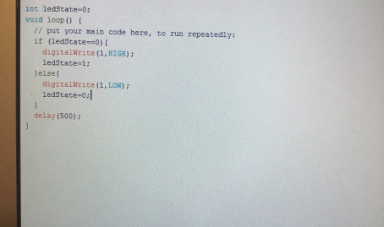
We then went through and coded a few in this case I programmed a Atmega328, which belongs to the AVR Mega family, and a ARM Cortex M7 which belongs to the Cortex family.To program both of the boards was fairly straightfoward. Starting the the Atmega328 being a standard Arduino Uno all that I had to do was select the settings in arduino for arduino UNO, and compile and run the code. For the ARM Cortex a bit more work had to be done where I had to install the compiler from a third party website, and put it into the appropriate arduino subfolder where I then had the choice to select the board and program it. Both boards were prorgammed with the standard blink code. I then used platform io to program the teensy with the blink code as well. To do this I just opened platform IO selectect the teensy as the board when making the project, and wrote a quick blink code, and all that was left was to compile and run it with the teensy connected no need to use thre third party installer like for arduino.
Following programming both boards we then tested the clock speed of the boards, and set a teensy board and a feather board, two boards form the same family to blink with no delay. We then used an osciloscope to compare the clock speeds of the board. We found that the teensy was capable of cyclying over ten times as fast which is comparable ot their differences in clock speeds. We then calculated the frequency using the information and determined in one second how many cycles happened. It should be noted the teensy is the only one of these boards powerful enough to infact just have a whole python interpreter if wanted.
Here we went through as a group and made a list of a bunch of mictrocontrollers, and attempted to program a few of them, as well as discuss there stats. For each board we had we found what microcontroller was on the board, and we found its bus width (the number of bits that can be sent to the CPU simultaneously) their family, the clock speed (how fast can the CPU process the information), the memory, the number of I/O pins, the logic level voltage, and the package style. Most of the microcontrollers were close to one another except for ARM family which were significantly more powerful than the rest.
We then went through and coded a few in this case I programmed a Atmega328, which belongs to the AVR Mega family, and a ARM Cortex M7 which belongs to the Cortex family.To program both of the boards was fairly straightfoward. Starting the the Atmega328 being a standard Arduino Uno all that I had to do was select the settings in arduino for arduino UNO, and compile and run the code. For the ARM Cortex a bit more work had to be done where I had to install the compiler from a third party website, and put it into the appropriate arduino subfolder where I then had the choice to select the board and program it. Both boards were prorgammed with the standard blink code. I then used platform io to program the teensy with the blink code as well. To do this I just opened platform IO selectect the teensy as the board when making the project, and wrote a quick blink code, and all that was left was to compile and run it with the teensy connected no need to use thre third party installer like for arduino.
Following programming both boards we then tested the clock speed of the boards, and set a teensy board and a feather board, two boards form the same family to blink with no delay. We then used an osciloscope to compare the clock speeds of the board. We found that the teensy was capable of cyclying over ten times as fast which is comparable ot their differences in clock speeds. We then calculated the frequency using the information and determined in one second how many cycles happened. It should be noted the teensy is the only one of these boards powerful enough to infact just have a whole python interpreter if wanted.
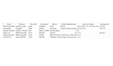 MCU Comparison Chart
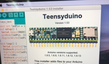 Teensy Programmer
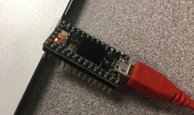 Teensy Board
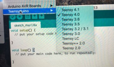 Setting Arduino to Program Teensy
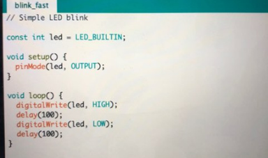 Blink Arduino
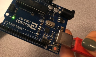 Arduino Uno
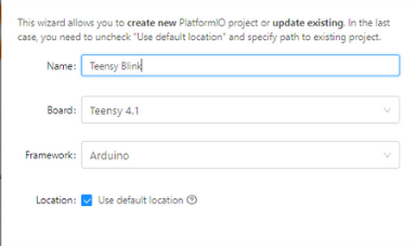 Teensy Platform Project
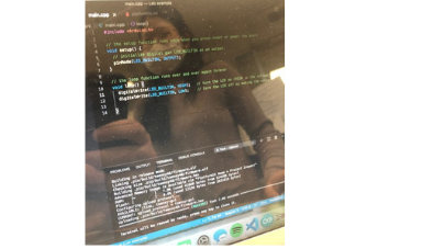 Platform IO Blink
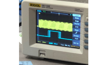 Oscilloscope Comparison
Programming with Arduino
For the next task we programmed the attiny 1616 with two different IDEs Arduino and Platform IO. Starting with Arduino we got the SpencerKonde library MegaTinyCore, and installed it in Arduino, hooked up the board combine the Tx and Rx from the USB to UART adapter to make a UPDI programmer, and programmed the board with a blink sketch. I was hoping to do the exact same thing on Platform IO, but was told more was expected from me...
For the next task we programmed the attiny 1616 with two different IDEs Arduino and Platform IO. Starting with Arduino we got the SpencerKonde library MegaTinyCore, and installed it in Arduino, hooked up the board combine the Tx and Rx from the USB to UART adapter to make a UPDI programmer, and programmed the board with a blink sketch. I was hoping to do the exact same thing on Platform IO, but was told more was expected from me...
 Blink Sketch
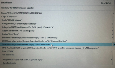 Attiny Settings in Arduino
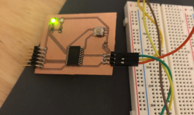 Programmed Microcontroller
Platform IO
For this next part I programmed the board in platformIO. Platform IO is an extension for VS Code which itself is not an IDE, but can get extensions to make it an IDE like plaform IO. Platform IO will automatically install most of the required dependencies, which makes programming the boards significantly easier. In order to program a board just go to home, new project, select the board, and name the file, then go to src and open main.cpp. Unfortunately to upload the board it requires pyupdi which you need to install yourself first using pip, then go to the config files and tell it to use pyupdi. Due to me not knowing how to add stuff to PATH on windows, I had to just give it the full path to access pyudi. I wrote a quick blink code and ran it to make sure everything was working.
For this next part I programmed the board in platformIO. Platform IO is an extension for VS Code which itself is not an IDE, but can get extensions to make it an IDE like plaform IO. Platform IO will automatically install most of the required dependencies, which makes programming the boards significantly easier. In order to program a board just go to home, new project, select the board, and name the file, then go to src and open main.cpp. Unfortunately to upload the board it requires pyupdi which you need to install yourself first using pip, then go to the config files and tell it to use pyupdi. Due to me not knowing how to add stuff to PATH on windows, I had to just give it the full path to access pyudi. I wrote a quick blink code and ran it to make sure everything was working.
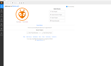 Home Screen
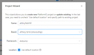 Make a new Project
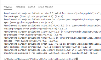 pip to get pyupdi
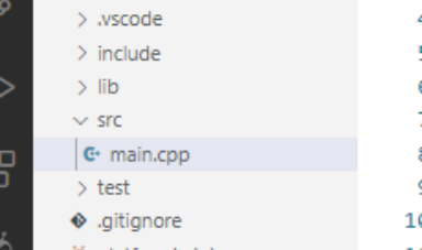 VS Code File Directory
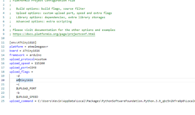 Config File
Final Program
I then made a final program for my board with two leds and a button in platform io. My plan was to make a program that would cycle through different led patterns when the button is pressed. To do this I first set up all my variables so declare my constants, made a class to cycle through the led patterns, and declared all the functions in my program. I then have my set up function which sets the two leds as outputs, and sets the button as an input with an internal pull up in order for the pin to not be floating. I then set the pin of the button to be an interrupt when it detects the voltage rise, so when the button is pressed and released. This interrupt will call the function that will make the led patter switch. I then wrote the loop function which is simply a switch statement that will run a different function depending on which pattern is currently set. Following I made the method that will return the current pattern, the method to switch to the next pattern or return to the first if at the last, and the interrup function which will run the next pattern method. Initially I made this function the board was skipping patterns, and I realized this was due to bounce, so I added a times using millis to make a software debouncer.
Each communication protocol works differently. Because I am lazy I used the easier one being serial communication which work using a transmit and receive terminals. The Tx pin hooks up to the Rx and the Tx to the Rx. Boards can then communicate by sending one bit at a time and checking the value on the clock to see if the message is rising or falling to determine the if the bit is a 1 or 0. In the group project which I do not have more photos of since we did it as a group and the board is dissasembled we connected the Boards this way Rx to Tx and Tx to Rx. In my personal design though I put two microcontrollers on one board and went FTDI to MC1 to MC2 back to FTDI daisy chaning them devices in an unconverntial way allowing for serial communication between three devices as long as they are programmed properly to pass on messages not designed for them (sort of like how I2C where slaves will ignore messages not for their address but a lot less good) Also check out my final project where I connected both my sensing board and servo board via i2c as slave devices to a rasberry pi as the master device.
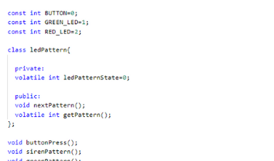 Global Values
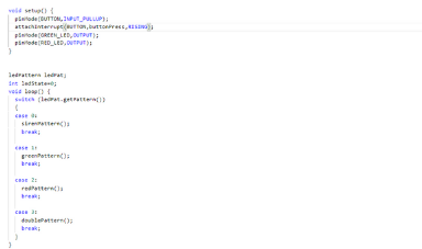 Set Up and Loop Function
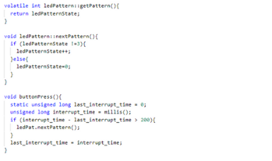 Methods and Interrupt Function
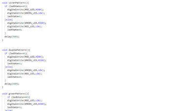 LED Patterns
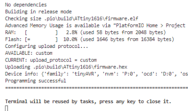 Building the Code
 Programmer
Click Here to Download the final cpp file!