Electronic Design
Microcontrollers
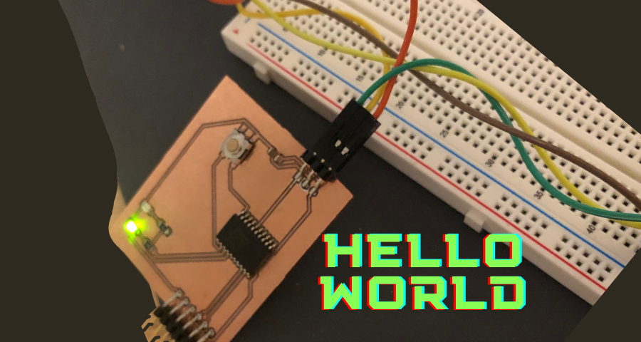
Microcontrollers are at their essence small computers. They share many of the same components as computers, memory, a CPU, GPIO pins to communicate with external devices and so forth. To use these microcontrollers effetively though they need to be linked to GPIO devices, since most of them (there are some exceptions) dont have wifi or a wireless means to communicate with them. In the board we are making this week we will be connecting our microcontroller to four distinct things. The first is two sets of LEDS each with their own current limiting resistor. The second is a button, and looking at the datasheet for the Attiny1616 I can see that all the pins can have internal pull up resistors, so there is no need to put an external one. The buttons and the LEDS wont be used this week, but will be used next week. The other things our microcontroller will be hooked to is a set of programming pins which will have VCC, Ground, and UPDI (Unified Programming and Debug Interface). It will also connect to a set of 4 pins which will allow for serial communication with the board.
Microcontrollers are at their essence small computers. They share many of the same components as computers, memory, a CPU, GPIO pins to communicate with external devices and so forth. To use these microcontrollers effetively though they need to be linked to GPIO devices, since most of them (there are some exceptions) dont have wifi or a wireless means to communicate with them. In the board we are making this week we will be connecting our microcontroller to four distinct things. The first is two sets of LEDS each with their own current limiting resistor. The second is a button, and looking at the datasheet for the Attiny1616 I can see that all the pins can have internal pull up resistors, so there is no need to put an external one. The buttons and the LEDS wont be used this week, but will be used next week. The other things our microcontroller will be hooked to is a set of programming pins which will have VCC, Ground, and UPDI (Unified Programming and Debug Interface). It will also connect to a set of 4 pins which will allow for serial communication with the board.
 CPU
CPU
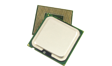
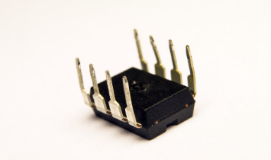 Microcontroller
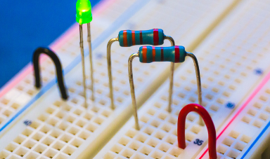 Current Limiting Resistor
Group Assignment
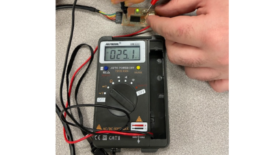
As a group we went over how to use two useful tools in electronics production. The first of which, and the most important one, being the multimeter. The multimeter is made up of two probes which can used to measure and test different values. The multimeter has a dial that lets the user choose what they want to test with the probes. Our multimeter had in order: AC Voltage, DC Voltage, Resistance, Diode, Continuity, Capacitance. AC Voltage and DC Voltage do as the nave implies and gives the voltage, or charge difference, between the two probes. Resistance gives the amount of resistance betweent the two probes, a good way to test resistors. Diode will send a small current through the probes and will show the voltage drop between the two. This can be used to test LEDs by simply checking in what direction the probes are to know which terminal is positive and which is negative by seeing how it lights up. It can also be used to test regular diodes with a voltage drop of 0.4 to 0.7 when in the right direction and an extrememely high voltage drop or OL (open line) when in the wrong direction. Then there is continuity test or colloquially the beep test, which sends a current through the probe and if it makes it from one probe to the other with no resistance than the multimeter will make a beep to show there is a connection. Finally capacitance shows the capcitance to be used on a capacitor in Farads. We tried out a few different modes on a model board and saw how the voltage would change when the button is pressed and how the LED would cause a slight voltage drop and such.
The second tool we learned how to use is the oscillosocope. The oscillosocope is an incredibly powerful tool, but far more niche and used far less often. The oscillosocope shows varying signal voltages on a two dimensional plot showing voltage vs time. It is capable of showing very small changes in voltage over small increments of time which is useful when needing to debug more precise things. For example it can be used to show bounding on a mechanical button, or can also be used to show signals via serial. Simmilar to the multimeter it has two probes, one for the signal, and the other to be grounded.
 Multimeter Button Not Pressed
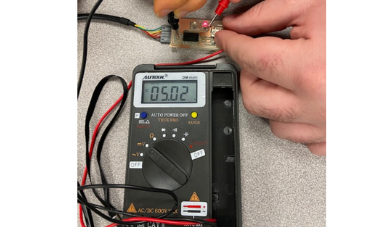 Multimeter Button Pressed
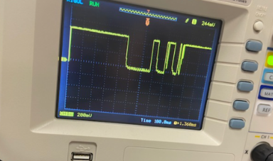 Oscilloscope
Setting up KiCAD
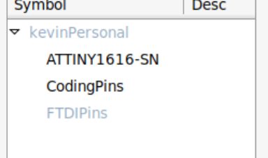
To set up KiCAD was really simple since I was on Debian. All I had to do was use apt to install kiCAD with the command apt-get install KiCAD, alongside all the other related KiCAD packages which included libraries, 3D models, and so forth. This got me KiCAD with all the preset libraries, unfortunately though because it is a Debian package everything is outdated, so the libraries are not the newest and do not yet include the series 1 microcontrollers such as the ATTINY 1616 that we are using. For this I just made myself my own personal library getting my footprints and schematic from UltraLibrariarian, and adding the microcontroller as a componenet on the library just importing in the files and linking them (schematic and footprint). Then I decided to make myself a componenet for the coding pins, so I copied the schematic for a 3 pin connector, and added labels to each one : VCC, Ground, and UPDI. All that was left to do was download the library of FabAcademy from GitHUB, and add its location into KiCAD for both the schematics and the footprints.
To set up KiCAD was really simple since I was on Debian. All I had to do was use apt to install kiCAD with the command apt-get install KiCAD, alongside all the other related KiCAD packages which included libraries, 3D models, and so forth. This got me KiCAD with all the preset libraries, unfortunately though because it is a Debian package everything is outdated, so the libraries are not the newest and do not yet include the series 1 microcontrollers such as the ATTINY 1616 that we are using. For this I just made myself my own personal library getting my footprints and schematic from UltraLibrariarian, and adding the microcontroller as a componenet on the library just importing in the files and linking them (schematic and footprint). Then I decided to make myself a componenet for the coding pins, so I copied the schematic for a 3 pin connector, and added labels to each one : VCC, Ground, and UPDI. All that was left to do was download the library of FabAcademy from GitHUB, and add its location into KiCAD for both the schematics and the footprints.
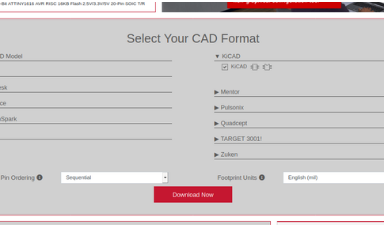 Getting Schematic and Footprint from From UltraLibrarian
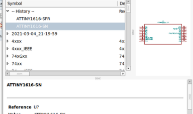 Adding attiny to library
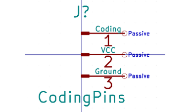 Adding Coding Pins to Library
Making Schematic
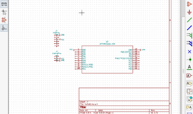
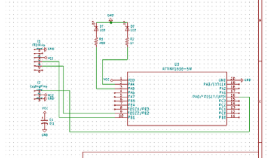
Now that I have my kiCad set up with both the schematics I need and footprint library all that is left is to make the schematic itself. This process was fairly simple since this is far from the first time I have used kiCad before. I startd by adding the microcontroller the attiny1616-s to the scematic since its the main componenet everything else will be connected to. I started by adding VCC and Ground labels to make it cleaner and easier to make the connections later. I then added the ftdi pins schematic from the fab academy library and wired up the four needed pins to attiny: VCC, GND, Tx, and Rx to be used later for serial communication between my computer and microcontroller over serial. I then added a three pin schematic that I made before in my custom library for the coding pins, and connected the coding pin to the coding pin of the attiny, and added GND and VCC tags. I also added a capacitor between vcc and gnd inm case of a voltage spike. Finally for next weeks project I also added two leds each going from a general GPIO pin to the LED to a current limiting resisitor to GND. I then added a button that went from ground to the button to another general GPIO pin, checking the datasheet I read that the attiny1616 has internal pullup resistors on all GPIO pins which I will use later instead of having an external pullup now.
To add any of the componenets I mentioned all I need to do is click the button on the side to add component, and select from the list. To add the tag, I just select the button just underneat the componenent one and select the tag from the list. To add connections betweent two componenets all I have to do is click with the mouse. Then when assigning footprints to each schematic all I have to do is select the footprint from the list, which I can filter by pin number, library, and search term.
 Selecting Component to add to Schematic
 Adding attiny to schematic
 Final Schematic
PCB Editor
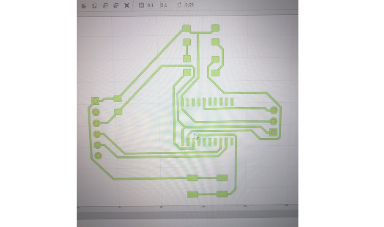
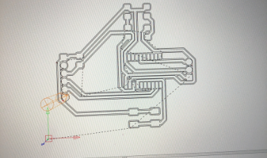
Now that I have my schematic made with all the connections between the components all that's left to do is lay them out on the PCB editor. To this first I need to go and assign footprints to schematics, which I go through and do for each component which were all 1206 led, resistor, and capacitor, the footprint I got from ultralibrarian for the attiny, 2.54 mm SMD male headers for the pins, and the Omron button from the Fab library. Once all the fottprints were assigned I exported net session, and opened the pcb editor when I then imported the net session. All the compoenent footprints were then visible in the editor. I layed them out so the connections intersected as little as possible and spread out the componenets a bit. I then went and set the design rules for the PCB. Now the next step for some people is very difficult since they insist to do it by hand for some ungodly reason, when the computer can do it better and more effeciently. This is ofcourse routing the traces, I choose to instead of routing the traces by hand and laying down the traces, instead I can just export the DSN session and open it in Freerouter. Freerouter is a free open source autorouting software avalable on all OS's including linux (which I used). All I have to do in free routing is go to the autorouter preferences indicate that it should be optimized for the F Cu only (since we only have a one sided mill), and import the DSN session. I then clicked on the autoroute button, wait till the autorouting is finished and export the session. I then have to just reopen the session in kiCad and its all the traces are made and routed perfectly. The autorouter even imports the design rules I set earlier, so they follow the design rules I set, I can check this by running the DRC and seeing no violations found. All that's left to do is export the Gerber file for the front copper layer by going to file plot to use later with FlatCAM.
Now that I have my schematic made with all the connections between the components all that's left to do is lay them out on the PCB editor. To this first I need to go and assign footprints to schematics, which I go through and do for each component which were all 1206 led, resistor, and capacitor, the footprint I got from ultralibrarian for the attiny, 2.54 mm SMD male headers for the pins, and the Omron button from the Fab library. Once all the fottprints were assigned I exported net session, and opened the pcb editor when I then imported the net session. All the compoenent footprints were then visible in the editor. I layed them out so the connections intersected as little as possible and spread out the componenets a bit. I then went and set the design rules for the PCB. Now the next step for some people is very difficult since they insist to do it by hand for some ungodly reason, when the computer can do it better and more effeciently. This is ofcourse routing the traces, I choose to instead of routing the traces by hand and laying down the traces, instead I can just export the DSN session and open it in Freerouter. Freerouter is a free open source autorouting software avalable on all OS's including linux (which I used). All I have to do in free routing is go to the autorouter preferences indicate that it should be optimized for the F Cu only (since we only have a one sided mill), and import the DSN session. I then clicked on the autoroute button, wait till the autorouting is finished and export the session. I then have to just reopen the session in kiCad and its all the traces are made and routed perfectly. The autorouter even imports the design rules I set earlier, so they follow the design rules I set, I can check this by running the DRC and seeing no violations found. All that's left to do is export the Gerber file for the front copper layer by going to file plot to use later with FlatCAM.
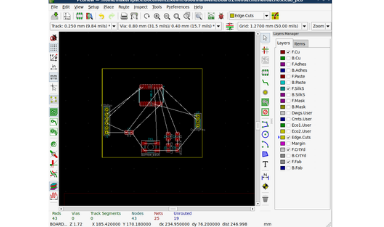 Importing Netlist and Moving Components
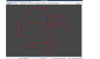 Using FreeRouter
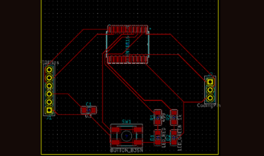 Importing Traces from FreeRouter
FlatCAM
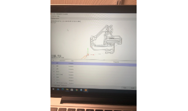
Now that I am done using kiCAD and I have my Gerber file I need to use FlatCAM, a CAM software, to create g-code for the mill. Using flatCAM is incredibly simple and actually uses vector information unlike MODS which decided a jgp was a better way to store vector data over a gerber file. First thing I do in FlatCAM is import in my gerber file. This places it usually far from the origin because of how it was positioned in kiCAD, so I then clicked on the Gerber file tab on the left, and put in the coorditaes to translate it by moving it closer to the origin point. I then went to the generate geometry option and put my tool diamter in 0.4 mm because its all in metric due to kiCAD being metric, and then generate geometry keeping the other setting default. This then creates an iso or isolation file which I can use to make the CNC pathing. Double clicking on the iso file I go to the create CNC jobs setting and set a cut z of -0.04 mm which is the cut depth, set the travel z to 1.5 mm, set the feed rante to 60 mm/min, and set the tool diameter to 0.4 and click on generate. This makes me a new file in the tab a CNC file which I can double click on and generate g-code from.
All thats left to do is create a gcode for the cutout of my board. To do this I go back to the gerber file tab, and scroll down to Board Cutout section. I set the gap size to 3 mm, and generate which creates for me a cutout file. I select the cutout file tab from the left. I then go to the cutout file, set the dool diamer of 1.2 mm, set the feed rate to 20 mm/min, and travel Z to 1.5 mm, and click on generate. This then generates a CNC file, and I export g-code as I did before. Resulting with me having two nc files one for the traces and out for the cut out.
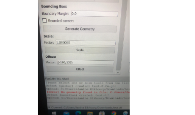 Offset Option
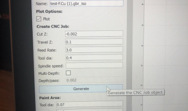 Generate CNC Job
 CNC Job
Candle and Milling the Board
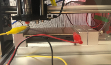
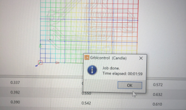
With the nc files ready to go all I need to do is mill the board. I am using my own 3018 mill I bought for a fraction of the cost of the Roland SRM-20 that I can have a proper workholding for and generate a height map. First thing I do is turn on my mill, and the motor (which is seperate from the mill.) I then home the mill using the home button in Candle the the free open source grbl controller application for my mill. Homing the mill will essentially zero it by moving the motots to the edge so the steppers can know where they are. I then put my 1/64 inch round bottom endmill that I got from Amazon and load it into the collet and tighten with an allen key. I then use some screws and clamps I have to hold down my PCB board on my wasteboard already attached to the mill. Next I move the end mill to be at where I want my x/y zero to be and zero the mill in those axis. I then attach two alligator clips one to the endmill and one to the pcb board, creating a zprobe, and going to settings setting the zprobe height to be 0. Then I click on the z-probe setting getting the z 0 at that point. I then create a height map accross the pcb which will get changes in height accross the pcb relative to the set z 0 which allows the cut to be consistent accross the board and not have some traces to deep or too shallow. I then save the height map and set it.
All that is left to do now is run the mill and wait. Once the traces are done milling I make sure not to touch on any of the zero settings to lose my zeros. I raise the endmill, move the gantry to the front, and remove the collet and endmill to replace the endmill with a 1.2 mm router bit I also got from Amazon for cheap. I brought the end mill back to the x-y zero point, attached the alligator clips, and ran the zprobe to get the z-zero. I then loaded the previous heighmap since the height map is relative to the z, and does not matter what endmill is in place as long as the z-zero is in the same point. I then load the cutout.nc file, and run it just like before and wait. When it's done, I remove the pcb board, snap it off the tabs due to lacking a better tool, and sand the edges.
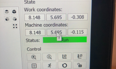 Coordinated Work vs Machine
 Z Probe
 Height Map
 Candle Live View
 Candle Live Steps
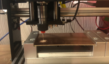 Milling the Board
Soldering and Continuity Tests
First thing I do is get a multimeter to run continuity tests on my milled board. I check to make sure that every trace is connected properly, and just to wear it is supposed to be connected to. Once I make sure the board milled out well, I can then start soldering. I am using solder paste, so I first heat up my board slightly with my heat gun, add some solder paste to the pins, and place the componenets on top and use the heatgun again to solidify the solder. Not much to describe here just used solder paste and a heat gun like last week. I first soldered the microcontroller, and then the leds, button, resistor, and capacitor, and then the smd horizontal pin headers. When done I ran more continuity tests to make sure everything was connected properly making sure to check the pins as well not just the board.
First thing I do is get a multimeter to run continuity tests on my milled board. I check to make sure that every trace is connected properly, and just to wear it is supposed to be connected to. Once I make sure the board milled out well, I can then start soldering. I am using solder paste, so I first heat up my board slightly with my heat gun, add some solder paste to the pins, and place the componenets on top and use the heatgun again to solidify the solder. Not much to describe here just used solder paste and a heat gun like last week. I first soldered the microcontroller, and then the leds, button, resistor, and capacitor, and then the smd horizontal pin headers. When done I ran more continuity tests to make sure everything was connected properly making sure to check the pins as well not just the board.
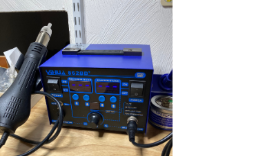 Soldering Station with Heat Gun
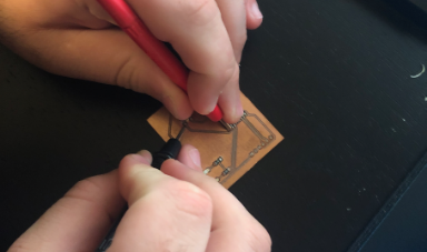 Continuity Tests
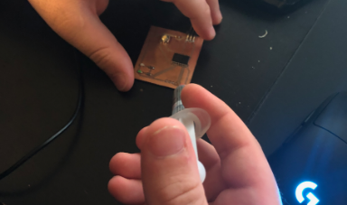 Soldering with Paste
Programming the Board
Now that the board is soldered and ready all is left to do is program it. I was fortunate to not run into any complications in this step, and it went overall smoothly. I first have to set up arduino to be able to program the attiny 1616. To do this I import the megaTinyCore library by Spencer Konde into arduino through preferences then install it by going to manage libraries. This sets up all the dependecies to program any avr board. Next up I have to connect the board to computer somehow, fortunatley the newest version of megaTinyCore allows for programming the series 1 boards over updi, so to do this I take a usb to serial adapter, and connect the tx and rx pins from the serial together with a resistor on a breadboard to make a updi connection, then connect the vcc, gnd, the updi to the thre pins on my board for coding. In arduino I then go to board manager, select megaTinyCore, and select the attiny 1616 board, and make sure all the other settings are the defualt settings. I then try to upload a blank sketch to see if it works which it does! All that is left for me then to do is download Neil's code from fabacademy website, and open it in arduino. I then uploaded his program to my board in the same manner, then unglugged the ftdi adapter from my breadboard, and plugged it into the board in the pins allocated to it. All that was left to do then was open the serial monitor through arduino, set the matching baud rate (the rate the micreocontroller will communicate over serial), and then type a message. The attiny would then return my message over serial one character at a time! And this showed that I succesfully designed, milled, and programmed my board.
Now that the board is soldered and ready all is left to do is program it. I was fortunate to not run into any complications in this step, and it went overall smoothly. I first have to set up arduino to be able to program the attiny 1616. To do this I import the megaTinyCore library by Spencer Konde into arduino through preferences then install it by going to manage libraries. This sets up all the dependecies to program any avr board. Next up I have to connect the board to computer somehow, fortunatley the newest version of megaTinyCore allows for programming the series 1 boards over updi, so to do this I take a usb to serial adapter, and connect the tx and rx pins from the serial together with a resistor on a breadboard to make a updi connection, then connect the vcc, gnd, the updi to the thre pins on my board for coding. In arduino I then go to board manager, select megaTinyCore, and select the attiny 1616 board, and make sure all the other settings are the defualt settings. I then try to upload a blank sketch to see if it works which it does! All that is left for me then to do is download Neil's code from fabacademy website, and open it in arduino. I then uploaded his program to my board in the same manner, then unglugged the ftdi adapter from my breadboard, and plugged it into the board in the pins allocated to it. All that was left to do then was open the serial monitor through arduino, set the matching baud rate (the rate the micreocontroller will communicate over serial), and then type a message. The attiny would then return my message over serial one character at a time! And this showed that I succesfully designed, milled, and programmed my board.
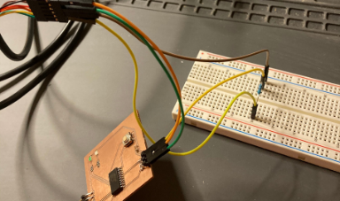 Breadboard Programmer I made USB to Serial to UPDI
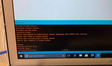 Uploading Sketch to Microcontroller
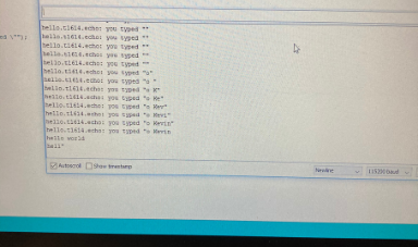 Serial Monitor Results Hello!
Problems I Encountered
In terms of problems I encountered there were not to many of them. The first problem I ran into was with my DRC not being proper with the clearnece of my board being set to 0.3 mm originally when the end mill is 0.4 mm, so I had to increase it. Since this mill is still new for me the next few problems all came with figuring out the mill. First I had to try a couple times to figure out the correct feed and cup depth settings for my board and endmill, but now it works like a charm.The next problem I had was with workholding, where I first tried a vice, but during the cutout step it would jump out which is problematic, so I instead held it down onto the spoilboard with the screws and clamps. My Final problem I ran into was when I initialy tried using through hold pinheaders instead of smd which also did not work well due to my PCB boards being incredibly cheap and low quality, so instead of cutting through would also rip off the copper layer on top around it. Final problem was also due to my chepo boards where when I used the heatgun it was too hot and completely burned the board causing a massive bubble to appear, so I had to set my heatgun at a lower than usual setting. Though once I gigured out these problems everything now works like a charm!
In terms of problems I encountered there were not to many of them. The first problem I ran into was with my DRC not being proper with the clearnece of my board being set to 0.3 mm originally when the end mill is 0.4 mm, so I had to increase it. Since this mill is still new for me the next few problems all came with figuring out the mill. First I had to try a couple times to figure out the correct feed and cup depth settings for my board and endmill, but now it works like a charm.The next problem I had was with workholding, where I first tried a vice, but during the cutout step it would jump out which is problematic, so I instead held it down onto the spoilboard with the screws and clamps. My Final problem I ran into was when I initialy tried using through hold pinheaders instead of smd which also did not work well due to my PCB boards being incredibly cheap and low quality, so instead of cutting through would also rip off the copper layer on top around it. Final problem was also due to my chepo boards where when I used the heatgun it was too hot and completely burned the board causing a massive bubble to appear, so I had to set my heatgun at a lower than usual setting. Though once I gigured out these problems everything now works like a charm!
Click Here to Download all the files from these projects!