Computer Controlled Cutting
What is Computer Controlled Cutting
Computer controlled cutting is a form of CNC specific to 2D machining including laser, plasma, water, vinyl, and other forms of cutting. It uses a CAD software just like other forms of machining, but a vector CAD package is required. Most parametric CAD softwares such as Fusion 360, Solid Works and FreeCAD all have 2D vector capabilities, however there are some easier to use, though arguable less useful softwares, such as Affinity Designer, Inkscape and Illustrator. This design can then be exported as the appropriate vector file such as SVG or DXF then imported into a CAM software which will ocnvert it into machine code to be loaded into the machine.
Computer controlled cutting is a form of CNC specific to 2D machining including laser, plasma, water, vinyl, and other forms of cutting. It uses a CAD software just like other forms of machining, but a vector CAD package is required. Most parametric CAD softwares such as Fusion 360, Solid Works and FreeCAD all have 2D vector capabilities, however there are some easier to use, though arguable less useful softwares, such as Affinity Designer, Inkscape and Illustrator. This design can then be exported as the appropriate vector file such as SVG or DXF then imported into a CAM software which will ocnvert it into machine code to be loaded into the machine.
 Illustrator
 Fusion 360
 Inkscape
Vinyl Cutting
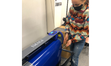
This week we used the vinyl cutter to cut out our team's logo. First off we designed our logo in a CAD software. Our group chose to use Affinity Designer, a software nearly identical to Illustrator except its only a single purchase else then a pricy recurring subscription. We designed our logo by getting an Alpha symbol, and placing a circle around it. It's a simple design, however a clear one, and one that will be simple to cut. Once our design was finished we exported it as a PNG image, and imported it into our vinyl cutters CAM software. The CAM software, SureCuts Pro, take in the PNG image and traces it in order to get vector information. We can then do simple CAD work in the CAM software, moving the cut, rotating it, duplicating it, and so forth. We then loaded the vinyl into the vinyl cutter machine and set the approriate speed and force settings for the vinyl we were using. Afer loading the vinyl we started the cut. Once the cut was finished we cut off the vinyl from the roll with an X-Acto knife. We then remved the excess vinyl from the cut off piece in a process called weeving. We then transfered the vinyl to the vinyl paper slowly. All that was then left was to transfer the vinyl on the paper to the item of interest in this case a mug I own.
This week we used the vinyl cutter to cut out our team's logo. First off we designed our logo in a CAD software. Our group chose to use Affinity Designer, a software nearly identical to Illustrator except its only a single purchase else then a pricy recurring subscription. We designed our logo by getting an Alpha symbol, and placing a circle around it. It's a simple design, however a clear one, and one that will be simple to cut. Once our design was finished we exported it as a PNG image, and imported it into our vinyl cutters CAM software. The CAM software, SureCuts Pro, take in the PNG image and traces it in order to get vector information. We can then do simple CAD work in the CAM software, moving the cut, rotating it, duplicating it, and so forth. We then loaded the vinyl into the vinyl cutter machine and set the approriate speed and force settings for the vinyl we were using. Afer loading the vinyl we started the cut. Once the cut was finished we cut off the vinyl from the roll with an X-Acto knife. We then remved the excess vinyl from the cut off piece in a process called weeving. We then transfered the vinyl to the vinyl paper slowly. All that was then left was to transfer the vinyl on the paper to the item of interest in this case a mug I own.
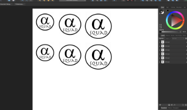 Designing Logo in Designer
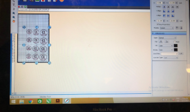 Using CAM Software Sure Cuts Pro
 Setting Vinyl Cutter Settings
 Cutting Vinyl off of Roll
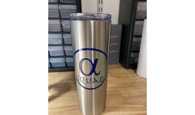 Final Vinyl Application
Characterizing our Laser Cutter
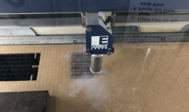
The main feature of our laser cutter my group was interested in analyzing was the kerf. The kerf is the amount of material that is removed during a cut. For this experiment we were trying to show that the speed and power has no effect on the kerf. We designed a very simple rectangle in Inksape with a known size and imported it to our machine's CAM software. We repeated the same rectangle cut multiple times with various powers and speeds. We noted all the values, and measured our cut out each time using a callipers. From there I brought the data into R and wrote a very simple script to run a multivariable linear regress on the data modeling kerf from speed and power and print a summary of the results as well as the average kerf. We found the average kerf of our laser cutter to be 0.18875, and from the linear model the coeffecient for the speed and power have a p-value greater than 0.05, so at an alpha of 0.05 we reject the alternative in favor of the null, meaning that the coefeccients are not significantly different then 0, so are not contributors to determing the kerf. If I had more time I would have liked to shown that what effects the kerf is the focus of the laser, though we did a quick demonstration to show this by defocusing the laser to move the bed far away from the source resulting in a cut with a very large kerf, as well as a small fire.
The main feature of our laser cutter my group was interested in analyzing was the kerf. The kerf is the amount of material that is removed during a cut. For this experiment we were trying to show that the speed and power has no effect on the kerf. We designed a very simple rectangle in Inksape with a known size and imported it to our machine's CAM software. We repeated the same rectangle cut multiple times with various powers and speeds. We noted all the values, and measured our cut out each time using a callipers. From there I brought the data into R and wrote a very simple script to run a multivariable linear regress on the data modeling kerf from speed and power and print a summary of the results as well as the average kerf. We found the average kerf of our laser cutter to be 0.18875, and from the linear model the coeffecient for the speed and power have a p-value greater than 0.05, so at an alpha of 0.05 we reject the alternative in favor of the null, meaning that the coefeccients are not significantly different then 0, so are not contributors to determing the kerf. If I had more time I would have liked to shown that what effects the kerf is the focus of the laser, though we did a quick demonstration to show this by defocusing the laser to move the bed far away from the source resulting in a cut with a very large kerf, as well as a small fire.
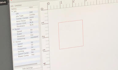 Epilog CAM Software
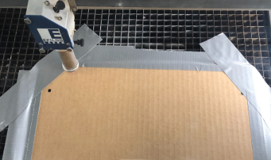 Work Holding
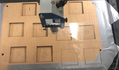 Experimental Cuts
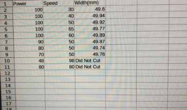 Raw Data
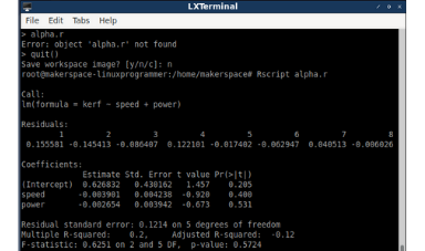 Linear Model
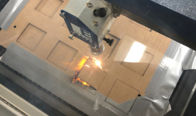 Defocusing the Laser
Press Fit Kit
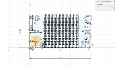
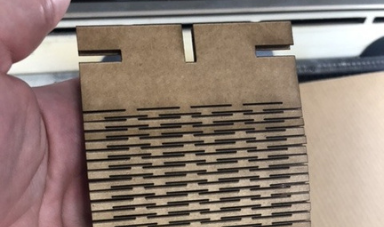
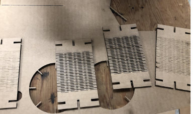
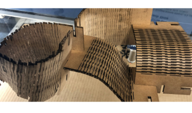
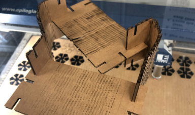
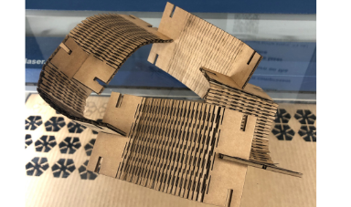
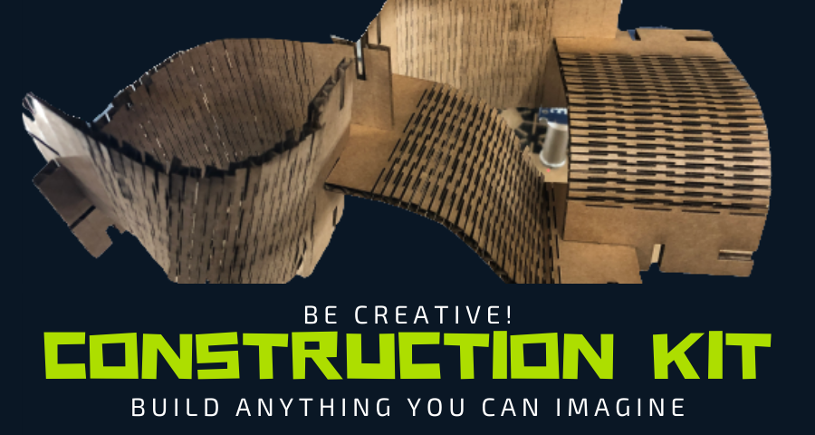
The final project to make is a press fit kit, which is essentially a bunch of cutout pieces that can be assembled in various different ways. To make this I used Fusion 360, a parametric CAD software. I decided to design my pieces with living hinges, and so started off by designing those. I found it best to use parameters to set information on just the first two lines, then use the rectangual pattern tool to copy the two lines multiple times to make the living hinge, and adjust the paramers as I see fit. Once the living hinge was designed I then added 3 slots on each side of the living hinge each of their width's being the thickniess of the carboard. All that was then left to do was cut out multiple of the pieces, and have fun building different designs in various different ways.
Overall the design worked well there were no adjustments needed. I did make however the parts of the press fit fitting together a slight bit smaller than the actual size of the cardboard in order to account for kerf by just a few millimeters. The settings I ended up using fro the vector cut on the laser cutter were 50 speed, 80 power, and 100 frequency. Overall I was lucky and there was no need to cut multiple times since I had a good solid fitting on the first try, but if needed I can readjust the parametric settings to change the box to make it easy to print again.
 Fusion Design
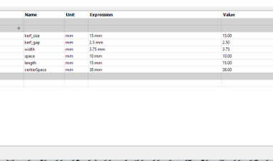 Fusion Parameters
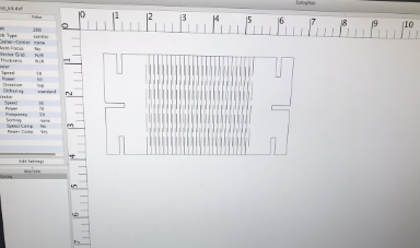 Epilog CAM Software
 Cutting out Part
 Singular Cutout Test
 Multiple Cutouts
 Assembly 1
 Assembly 2
 Assembly 3
Click Here to Download all the files from these projects!