3D Computer Controlled Machining
Intro to CNC
CNC standing for computer numerical control is a system that will take take in programmed instructions to automatically run a job whether it be milling, lathe, drill... and so forth. Technically 3d printers, laser engravers, vinyl cutter, and any other tool you program using a computer is a CNC machine. In order to use a CNC machine one need to take their CAD file and import it into a CAM software which will then turn the design into machine code the machine can understand. Then you simply using the machines controller or control panel in order to zero it and run the machine code.
The machine we are using in this project is a mill and more specifically a 3-axis mill. A mill is composed of a few different important parts that are crucial to understand in order to use it effectively. Going through the basic parts there is the gantry which is a general term used for the portion of the mill that moves along the axis, there is then the spindle which is a motor that spins at around 18000 RPM. Connected to the spindle is the collet and collet nut which will hold the bit in place. The bit simply being the actual tool used to make the cut. There is a vast array of available bits (that I will talk to you about buying) more of, from endmills to drills, to surfacing tools, tapered bits and more. Next to the collet and bit and surrounding it is the dust collector connected to a vaccum to keep wood and other material dust from flying everywhere. Finally the last thing to discuss is the axis. The axis are the direction the spindle can move in (NOT THE GANTRY). Our CNC mill is 3 axis, and so can move in the x,y, and z directions allowing it to do 2 axis, 2.5 axis, and 3 axis milling operations. In the other room we have a 5-axis mill meaning that the spindle can now be angled in diagonal directions allowing for more complex cuts.
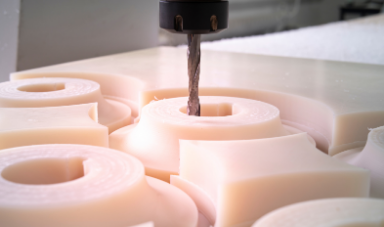 3 Axis Mill
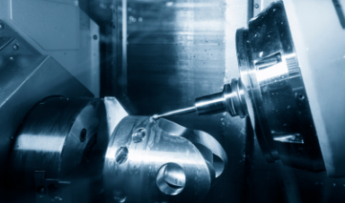 5 Axis Mill
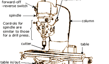 Anatomy of a Mill
 Endmill Bits
 Dust Collector
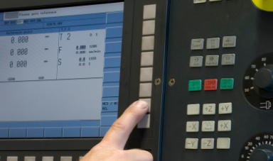 CNC Mill Controller
Group Assignment
For this group assignment we tested our CNC machine the axiom precesion CNC mill. We tested out a few things and went through important terminology related to the mill. We discussed allignment of the CNC which is the alignment of the gantry, the bed, and the spindle all together, and how long they typically stay in alignment.Run out which is when the spindle and tool come out of alignment more often encountered when working with denser material such as aluminium. Speed is the roation of the toolpath in rpm, and feed is how path the tool is moving relative to the stock typically is mm/minute (in Fusion 360).
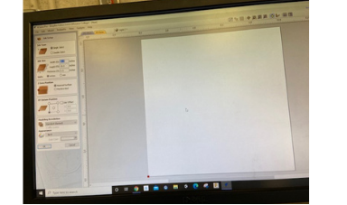
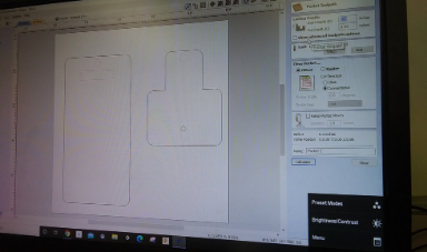
To test out all of this stuff we made a quick design in V-Carve using a 1/4 inch downcut endmill, using the reccomended speed and feed settings, and measured the cut out stock to determine the precesion and kerf of the mill. We designed an Iphone stand in V-Carve, and made sure to add fillets to the edges due to the mill not being very good at making sharp angles. We then processed the design, and laoded the g-code to load into the machine. We loaded the 1/4 inch endmill into the collet, turned on the vacuum and ran the cut.
The final cut was then measured and found to be withing a few fraction of an inch of their intended cut size.
For this group assignment we tested our CNC machine the axiom precesion CNC mill. We tested out a few things and went through important terminology related to the mill. We discussed allignment of the CNC which is the alignment of the gantry, the bed, and the spindle all together, and how long they typically stay in alignment.Run out which is when the spindle and tool come out of alignment more often encountered when working with denser material such as aluminium. Speed is the roation of the toolpath in rpm, and feed is how path the tool is moving relative to the stock typically is mm/minute (in Fusion 360).
To test out all of this stuff we made a quick design in V-Carve using a 1/4 inch downcut endmill, using the reccomended speed and feed settings, and measured the cut out stock to determine the precesion and kerf of the mill. We designed an Iphone stand in V-Carve, and made sure to add fillets to the edges due to the mill not being very good at making sharp angles. We then processed the design, and laoded the g-code to load into the machine. We loaded the 1/4 inch endmill into the collet, turned on the vacuum and ran the cut.
The final cut was then measured and found to be withing a few fraction of an inch of their intended cut size.
 Setting Stock Dimensions
 Adjusting Cut Settings
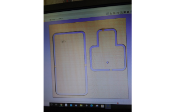 Simulating Cut
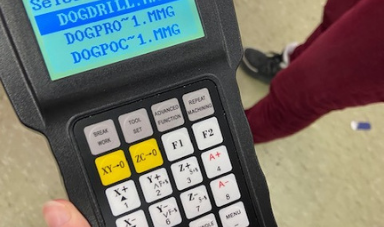 Axiom Controller
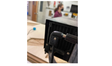 Plugging in Z-Probe
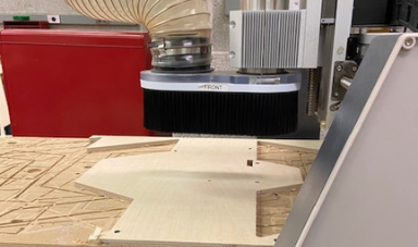 Milling
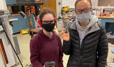 Group
Group
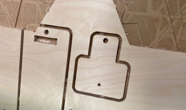 Cutout
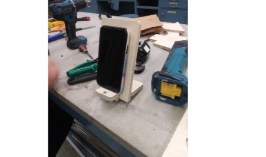 Final Assembly
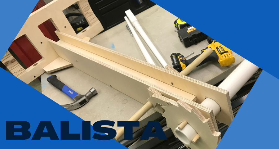
Balista Prototype
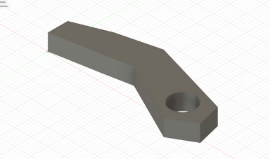
For this project my friend, David Frey, and I decided to attempt to make a ballista, we ran into a lot of problems along the way but tried our best to find solutions for all of them. Starting off this project we thought it be best to model and print the locking mechanism in Fusion 360. We sketched some ideas and discussed a few different locking mechanisms, but agreed in the end on a locking mechanism with a gear with angled teeth. A locking mechanism of sorts will then get stuck in the teeth if attempted to rotate the gear in the opposite direction. This model was 3D printed and tested, but was found to not work due to the gear not actually falling back into place as it was supposed to, and needing to go against gravity to get back where it was supposed to be due to issues regarding center of mass of the locking mechanism. We redesigned it so the locking mechanism would fall towards the locking mechanism instead of away.
For this project my friend, David Frey, and I decided to attempt to make a ballista, we ran into a lot of problems along the way but tried our best to find solutions for all of them. Starting off this project we thought it be best to model and print the locking mechanism in Fusion 360. We sketched some ideas and discussed a few different locking mechanisms, but agreed in the end on a locking mechanism with a gear with angled teeth. A locking mechanism of sorts will then get stuck in the teeth if attempted to rotate the gear in the opposite direction. This model was 3D printed and tested, but was found to not work due to the gear not actually falling back into place as it was supposed to, and needing to go against gravity to get back where it was supposed to be due to issues regarding center of mass of the locking mechanism. We redesigned it so the locking mechanism would fall towards the locking mechanism instead of away.
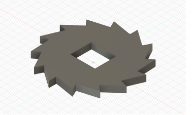 Locking Gear
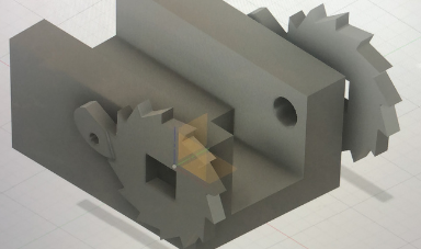 Prototype Assembly
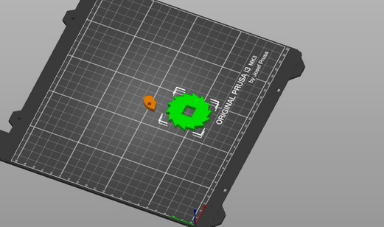 Importing into Slicer
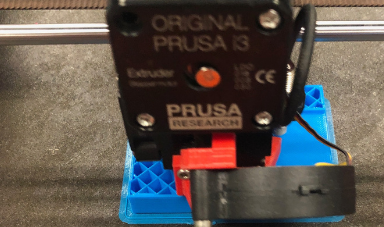 Printing
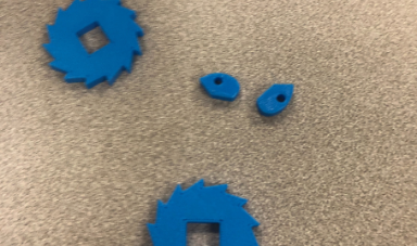 Printed Gears
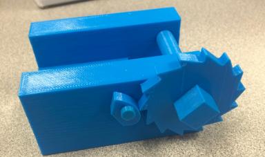 Prototype Print
CAM
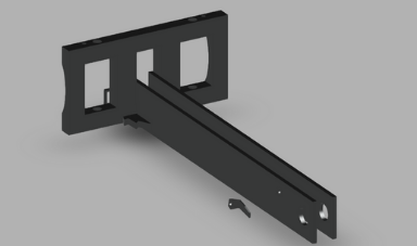
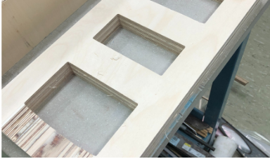
The part of the project to do was design the individual components to be milled. We made an initial design, but ofcourse this could not simply be milled out since we did not have access to a giant stock of wood and multiaxis milling, so we had to approach the problem in components. We used the designs for the gear and locking mechanisms and set their heights and widths to fit comfortably in the stock we have. We then made a componenent for the rails which was broken up into 4 diffent bodies, 2 walls, one track, and one support. Finally we made the tensioning holder which needed to be fairly thick so we broke its width into three different bodies.
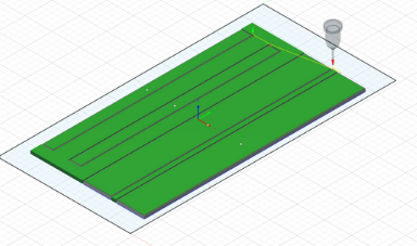
We then layed out the bodies flat into two different files. The first file contained the locking gears, mechanism, and rails, while the second file contained the tensioning component. To mill the first file all was needed was a gew pocket cuts for the holes, an a contour cut with tabs to cut out the parts. For the tensionining componenet we had to use a 3D adaptive milling for the curved protion, and then a contour cut to cut out the objects. We ran into some problems with Z axis limit which we quickly found out was us messing up and not placing the origin in the correct location.
The part of the project to do was design the individual components to be milled. We made an initial design, but ofcourse this could not simply be milled out since we did not have access to a giant stock of wood and multiaxis milling, so we had to approach the problem in components. We used the designs for the gear and locking mechanisms and set their heights and widths to fit comfortably in the stock we have. We then made a componenent for the rails which was broken up into 4 diffent bodies, 2 walls, one track, and one support. Finally we made the tensioning holder which needed to be fairly thick so we broke its width into three different bodies.
We then layed out the bodies flat into two different files. The first file contained the locking gears, mechanism, and rails, while the second file contained the tensioning component. To mill the first file all was needed was a gew pocket cuts for the holes, an a contour cut with tabs to cut out the parts. For the tensionining componenet we had to use a 3D adaptive milling for the curved protion, and then a contour cut to cut out the objects. We ran into some problems with Z axis limit which we quickly found out was us messing up and not placing the origin in the correct location.
 Fusion Assembly
 Altered Locking Mechanishm
 2D Pocket Cut
 2D Contour Cut with Tabs
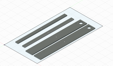 Rails, gears, and locking mechanisms
 Tensioning holder
Milling
For the milling section we ran into some problems. The feed rate on the machine was far to slow compared to what was put in for it to go. The first cut nearly took an hour, and we were not willing to wait that long again. Instead I went through the controller and found a reset to back up, but which messed up more things on the machine. I then had to go through each individual setting, look them up, and set them properly, it seems like the backup stored on our controller originally was not designed for our machine. I went through had to reset all the advanced settings including how and what it read from the nc file, disable tool change options, set up the correct value for the pulses for the stepper motors, and get a pair of calipers measure the z probe, and a meter stick to measure the table size and set all those settings back. Finally everytyhing was up and running again, but we lost our zero point in the mess. So we decided to go back to fusion set the origin at the edge of one of the holes we milled and used that as a reference which worked like a charm. We cam back the next day and milled the second board as well.
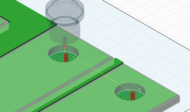
The process to actually mill the board is incedibly simple all we had to do was put some tape on the back of our stock and screw it into the spoil board. We then set the XY zero location to the desired location, and used the Z-probe which works by simply closing a circuit to zero the z axis. All thats left from there is to make sure the correct bit is loaded into the collet, turn on the vacuum, and run the file. We did lead it was possible to decrease the feed by fixed percentage interval using the contorller, but we did not need to, we did however slighly adjust the speed using the knob found on the machine base.
For the milling section we ran into some problems. The feed rate on the machine was far to slow compared to what was put in for it to go. The first cut nearly took an hour, and we were not willing to wait that long again. Instead I went through the controller and found a reset to back up, but which messed up more things on the machine. I then had to go through each individual setting, look them up, and set them properly, it seems like the backup stored on our controller originally was not designed for our machine. I went through had to reset all the advanced settings including how and what it read from the nc file, disable tool change options, set up the correct value for the pulses for the stepper motors, and get a pair of calipers measure the z probe, and a meter stick to measure the table size and set all those settings back. Finally everytyhing was up and running again, but we lost our zero point in the mess. So we decided to go back to fusion set the origin at the edge of one of the holes we milled and used that as a reference which worked like a charm. We cam back the next day and milled the second board as well.
The process to actually mill the board is incedibly simple all we had to do was put some tape on the back of our stock and screw it into the spoil board. We then set the XY zero location to the desired location, and used the Z-probe which works by simply closing a circuit to zero the z axis. All thats left from there is to make sure the correct bit is loaded into the collet, turn on the vacuum, and run the file. We did lead it was possible to decrease the feed by fixed percentage interval using the contorller, but we did not need to, we did however slighly adjust the speed using the knob found on the machine base.
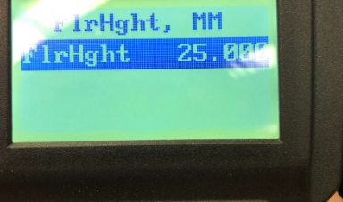 Z Probe Height Settings
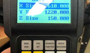 Table Size Settings
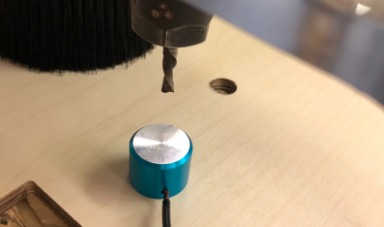 Zeroing the Machine with Z Probe
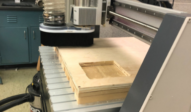
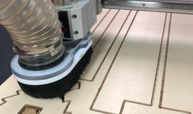 Milling the Board
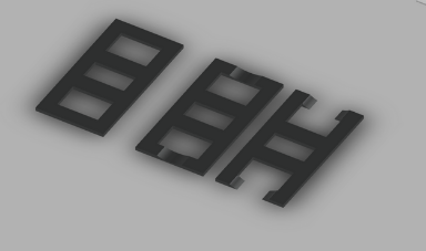
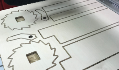 First Milled Board
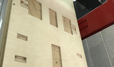 Second Milled Board
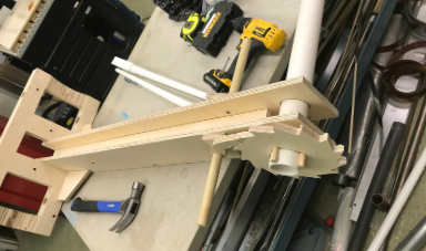
Assembling the Project
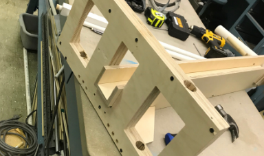
All that was left to do was assemble the project. The first thing to do was cut each comonenet still connected to the stock by tabs. Then we went through and sanded everything so it is all smooth. We started of by attaching the rails together using screws, and pre drilling to avoid splintering. After doing this and assembing the rails we realized that we needed to add tube for the locking mechanism from the inside which meant we had to disassemble it, attach the wooden dowel for the locking mechaninsm, and rescontruct the rail. Following that we were hoping to have a large square metal stock we could use a lathe to turn cylidrical to connect the locking gears, we could not find one and were running out of time, so had to improvise with some pvp and pieces of wood. We went on to atack the axle and gears and locking mechanism all to the rails completing the first part of the ballista.
First we stacked the 3 bodies of the tensioning componenet on top of one another and screwed them all together to make them into onr part. Next we went and drilled holes into the tensioning componeneonent to allow the rope to go into. We then realized that we made the whole thing was to small, and there was not adequate room to manipulate the rope propoely, and attack the needed dowels that will be pulled back. We soon gave up on this and decided to return to it some time in the future. We then went to attach the componenent just assembled to the rails, but had difficulty screwing the wood in parallel to the layers of plywood, and so decided instead to try attaching them with support components. Though in the end the ballista did not work as intended, it was still a fun project with plenty of learning oppertunities.
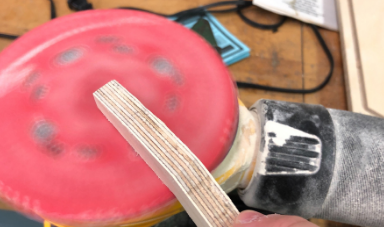 Sanding all Components
 Axis to locking mechanism
 Jamming the gear in the axis
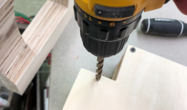
 Screwing the Rails together
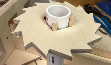
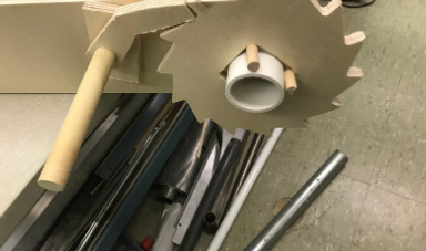 Gear and locking Mechanism
 Assembling Tension Rack
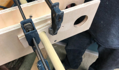
 Adding holes in Tension Assembly
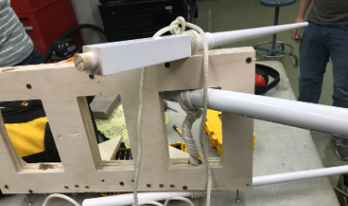 Attempting to Add Rope to Ballista
 Assembled Ballista
Click Here to Download all the files from these projects!