3D Printing and Scanning
Additive Manufacturing
Additive manufacturing is any process where material is stocked on top of each other in order to create a final design. Juat like any other form of digital fabrication it all starts in a CAD software where the design in made, imported into a CAM software to generate g-code for the machine, and then run on the appropriate machine. The most common type of additive manufacturing is known as fused filament fabrication (FFF), however most people just refer top this type as 3D printing. Another common name is FDM or Fused Depositon Modeling, however that is a trademarked term. Fused Filament Fabrication is the cheapest process, and can produce some of the strongest prints depedning on the filament of choice. Another type is known as stereolithography (SLA) which consists of using light to polymerize monomers and create designs. This form of printing is far more expensive then FFF, however can produce much higher quality prints at lower work. SLA printing is common to see in various medical fields and dentistry where it can make crowns and other useful components. Though the cured resin is slightly stronger than PLA it is significant weaker than other filaments such as PC and PETG. Finally a third type I am going to mention is selective laser sintering (SLS). SLS can produce the most durable parts requiring no supports to be built. It is most commonly used to make final prototypes before moving to produiction where injection moulding will likely be used. The big downside is the major cost of printing these componenets, whith the machines themselves causing upwards of 15 thousand dollars.
Additive manufacturing is any process where material is stocked on top of each other in order to create a final design. Juat like any other form of digital fabrication it all starts in a CAD software where the design in made, imported into a CAM software to generate g-code for the machine, and then run on the appropriate machine. The most common type of additive manufacturing is known as fused filament fabrication (FFF), however most people just refer top this type as 3D printing. Another common name is FDM or Fused Depositon Modeling, however that is a trademarked term. Fused Filament Fabrication is the cheapest process, and can produce some of the strongest prints depedning on the filament of choice. Another type is known as stereolithography (SLA) which consists of using light to polymerize monomers and create designs. This form of printing is far more expensive then FFF, however can produce much higher quality prints at lower work. SLA printing is common to see in various medical fields and dentistry where it can make crowns and other useful components. Though the cured resin is slightly stronger than PLA it is significant weaker than other filaments such as PC and PETG. Finally a third type I am going to mention is selective laser sintering (SLS). SLS can produce the most durable parts requiring no supports to be built. It is most commonly used to make final prototypes before moving to produiction where injection moulding will likely be used. The big downside is the major cost of printing these componenets, whith the machines themselves causing upwards of 15 thousand dollars.
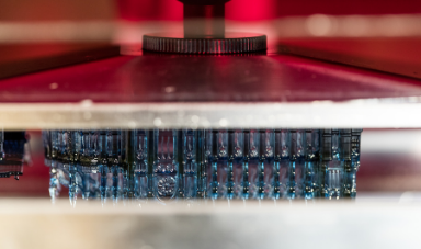 SLA Printing
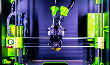 FFF Printing
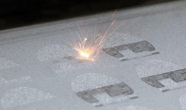 SLS Printing
Prusa Specifications and Opinions
The Prusa we tests was an I3 MK3S which has a build volume of 250x250x200 mm, can take in a filament of 1.75 mm, has a max extruder temperature of 300 degrees Celcius, and a max print ped temperature of 120 degrees Celcius. This printer can produce anything standard of any FFF printer, without anyspecial features else than a CAM software specically designed for it. The Prusa printer has an slightly larger than average print bed, not capable of doing large prints which can be done with custom large printers or belt printers like the new CR-30, and will struggle to print very quickly, and is limited by a filament of 1.75 mm which can slow down print speed. However with an extruder temperature reaching 300C and bed reaching 120C there should be no problems to print any available FFF compatible filament on the market. In addition its level of construction, and further callibration potential such as the nylock mod, allow this printer to produce extremely consistent solid prints. There is a reason the Prusa I3MK3S is my personal choice of FFF printer (this opinion has no affiliantion with the attrocity the MMU machine is).
The Prusa we tests was an I3 MK3S which has a build volume of 250x250x200 mm, can take in a filament of 1.75 mm, has a max extruder temperature of 300 degrees Celcius, and a max print ped temperature of 120 degrees Celcius. This printer can produce anything standard of any FFF printer, without anyspecial features else than a CAM software specically designed for it. The Prusa printer has an slightly larger than average print bed, not capable of doing large prints which can be done with custom large printers or belt printers like the new CR-30, and will struggle to print very quickly, and is limited by a filament of 1.75 mm which can slow down print speed. However with an extruder temperature reaching 300C and bed reaching 120C there should be no problems to print any available FFF compatible filament on the market. In addition its level of construction, and further callibration potential such as the nylock mod, allow this printer to produce extremely consistent solid prints. There is a reason the Prusa I3MK3S is my personal choice of FFF printer (this opinion has no affiliantion with the attrocity the MMU machine is).
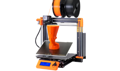 Prusa I3MK3S
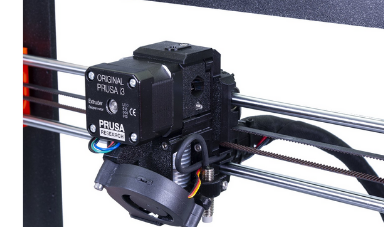 Prusa Extruder
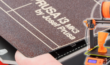 Prusa Print Bed
Characterizing our 3D Printer
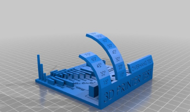
To properly characterize our printer I found a test print on the internet that would test the Prusa's ability to create overhands, and make small extrusions and holes. The print was found online, and imported into Prusa Slicer. I scaled it down by a known amount to still be able to measure each part to make sure they print to the appropriate size. I printed in the test at 0.15 mm, with 15% infill, on the Prusa I3MK3. The print itself was only a 1hr print using a unlabelled roll of filament (foreshadowing). There was no complications in printing the model, or any other problems.
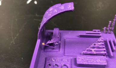
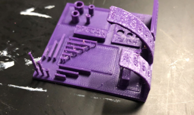
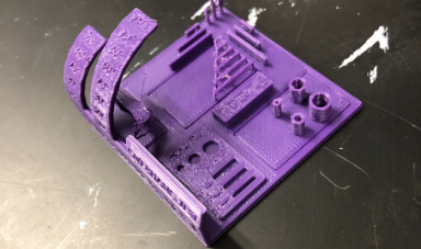
The results gave a lot of information on the printer. Starting off from obvious glance there was a lot of stringiness and melted sections this is due to poor temperature settings for the filament chosen. However after measurinmg each part of the test print with calipers it was found that they are fairly consistent in getting near their expected value to a fraction of a milimeter. Less than that however they are not consistent. This was seen accress all the holes, gaps, and extruded structures. The print seemed to be fine doing overhang up to 30% with increasigly poor results pass that value. Overall this shows a lot of promise for the printer allowing me to make standard componenets, and even various threads as long as the TPI values are not to large. Only issue is for more complicated prints where supports could potentially lose the accuracy of the print, or not be easy to remove and cause damage to the model when attempting to remove. I could attempt to slow dows the print on these overhangs though perhaps to alleviate the problem. However in conclusion for most simple prints, including basic threading and other semi precise components the FFF printer should be capable of manufacturing without a problem.
Various parts of the callibration print gives different information on the printer. Starting with the overhang test, it showed how far overhang the printer can print without needing supports. It started to show signs of failing around 40 to 60 degrees. In addition the overhang test checks for overextrusion which is the case if there are horizontal lines on the overhang test, which there were not. Following there are various pillars vertical and horizontal, these will test two things, firstly they are each a fixed size and easy to measure with calipers which lets us test the prevesion of the printer, and since they are nearby to one another it also lets us test for stringiness. In our case the precesion was accurate within a fraction of a milimeter, however there was a fair amount of stringiness which would be caused by poor temperature and extrusion settings. The circles made can also be tested as easily with a pair of calipers to determine their precesion, and we can check their interior for stringiness, which there was, and the walls themseves to check how smooth they are for potential extrusion problems. The edges of the circles as well are a good place to check for belt issues, since to make them cleanly the belts need to be the proper tension and the extrusion should also be really good. Then there are the small thin holes, which makes sure your printer can create the small gaps, and characters cleanly. We saw some problems on the characters showing some signs of over extrusion, and a lot of stringiness due to poor temperature settings, and the gaps were clean, but showed signs of stringiness. Finally the flat base, shows PID callibration, and by laying in of a callibration plate the base seemed flat showing proper PID callibration.
Overall the slight shrinkage of the design is propably due to poor printer callibration having to do with poor temperature settings as seen with the excessive amount of stringiness. The settings used to print this design were the standard genereic PLA settings on Prusa Slice at 0.15 mm, 15% infill, tested using hatchbox filament. Extrudent temp was 215 (which is to hgigh for hatchbox), bed temp at 60, fan set to be always enabled and cooling, with a max volumentric speed of 15.
To properly characterize our printer I found a test print on the internet that would test the Prusa's ability to create overhands, and make small extrusions and holes. The print was found online, and imported into Prusa Slicer. I scaled it down by a known amount to still be able to measure each part to make sure they print to the appropriate size. I printed in the test at 0.15 mm, with 15% infill, on the Prusa I3MK3. The print itself was only a 1hr print using a unlabelled roll of filament (foreshadowing). There was no complications in printing the model, or any other problems.
The results gave a lot of information on the printer. Starting off from obvious glance there was a lot of stringiness and melted sections this is due to poor temperature settings for the filament chosen. However after measurinmg each part of the test print with calipers it was found that they are fairly consistent in getting near their expected value to a fraction of a milimeter. Less than that however they are not consistent. This was seen accress all the holes, gaps, and extruded structures. The print seemed to be fine doing overhang up to 30% with increasigly poor results pass that value. Overall this shows a lot of promise for the printer allowing me to make standard componenets, and even various threads as long as the TPI values are not to large. Only issue is for more complicated prints where supports could potentially lose the accuracy of the print, or not be easy to remove and cause damage to the model when attempting to remove. I could attempt to slow dows the print on these overhangs though perhaps to alleviate the problem. However in conclusion for most simple prints, including basic threading and other semi precise components the FFF printer should be capable of manufacturing without a problem.
Various parts of the callibration print gives different information on the printer. Starting with the overhang test, it showed how far overhang the printer can print without needing supports. It started to show signs of failing around 40 to 60 degrees. In addition the overhang test checks for overextrusion which is the case if there are horizontal lines on the overhang test, which there were not. Following there are various pillars vertical and horizontal, these will test two things, firstly they are each a fixed size and easy to measure with calipers which lets us test the prevesion of the printer, and since they are nearby to one another it also lets us test for stringiness. In our case the precesion was accurate within a fraction of a milimeter, however there was a fair amount of stringiness which would be caused by poor temperature and extrusion settings. The circles made can also be tested as easily with a pair of calipers to determine their precesion, and we can check their interior for stringiness, which there was, and the walls themseves to check how smooth they are for potential extrusion problems. The edges of the circles as well are a good place to check for belt issues, since to make them cleanly the belts need to be the proper tension and the extrusion should also be really good. Then there are the small thin holes, which makes sure your printer can create the small gaps, and characters cleanly. We saw some problems on the characters showing some signs of over extrusion, and a lot of stringiness due to poor temperature settings, and the gaps were clean, but showed signs of stringiness. Finally the flat base, shows PID callibration, and by laying in of a callibration plate the base seemed flat showing proper PID callibration.
Overall the slight shrinkage of the design is propably due to poor printer callibration having to do with poor temperature settings as seen with the excessive amount of stringiness. The settings used to print this design were the standard genereic PLA settings on Prusa Slice at 0.15 mm, 15% infill, tested using hatchbox filament. Extrudent temp was 215 (which is to hgigh for hatchbox), bed temp at 60, fan set to be always enabled and cooling, with a max volumentric speed of 15.
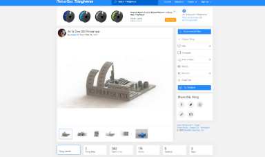 Model from Thingiverse
 Model from Thingiverse
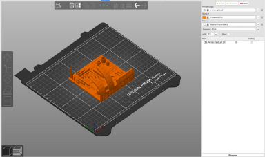 Importing into Slicer
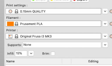 Slicer Print Settings
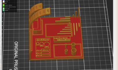 Layer View Slicer
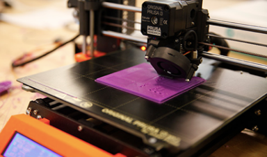 Printing the Test
 Result View 1
 Result View 2
 Result View 3
Non Subractive Design
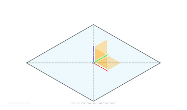
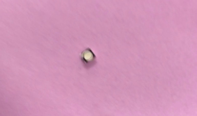
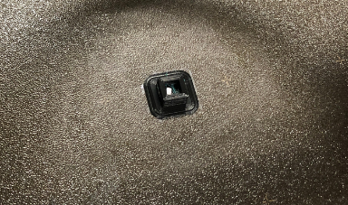
For this next part we had to design a componenet that could not be designed with subtractive manufacturing. Now there are a variety of options available, and really what to consider for a design like this is even with a 5 axis mill, there are areas it simply cannot reach du to the bit or collet being to big, or simply due to the area being inacessible. For my project I went with something incredibly simple, a hollow cube. Not fancy at all, but absolutely impossible to make via subttractive manufacturing since to removed the interior part you would ne a whole, in which case it won't be a closed cube anymore. In addition to show that its hollow, I will be placing an item inside the cube, so one can shake it and hear that it is hollow. First I designed it in Fusion 360. All I did was make a 30 by 30 center rectangle sketch, extruded it by 30 mm and then shelled the body with a 3mm wall. I then imported it into slicer, and in layer view added an interrupt about halfway for a filament change. Overall it was just a 15 minute print. I let it print, and instead of changing the filament at the pause I put in my rattler, which was a small SMD led I found lying around, and then continued the print. So in the end I got a sealed hollow box with something inside, something impossible to make via subtractive manufacturing. Measuring the cube it was about the expected size a bit smaller on one edge than the other but this was propably due to poor printer callibrationa nd print settings with possible issues ont he first layer callibration step.
For this next part we had to design a componenet that could not be designed with subtractive manufacturing. Now there are a variety of options available, and really what to consider for a design like this is even with a 5 axis mill, there are areas it simply cannot reach du to the bit or collet being to big, or simply due to the area being inacessible. For my project I went with something incredibly simple, a hollow cube. Not fancy at all, but absolutely impossible to make via subttractive manufacturing since to removed the interior part you would ne a whole, in which case it won't be a closed cube anymore. In addition to show that its hollow, I will be placing an item inside the cube, so one can shake it and hear that it is hollow. First I designed it in Fusion 360. All I did was make a 30 by 30 center rectangle sketch, extruded it by 30 mm and then shelled the body with a 3mm wall. I then imported it into slicer, and in layer view added an interrupt about halfway for a filament change. Overall it was just a 15 minute print. I let it print, and instead of changing the filament at the pause I put in my rattler, which was a small SMD led I found lying around, and then continued the print. So in the end I got a sealed hollow box with something inside, something impossible to make via subtractive manufacturing. Measuring the cube it was about the expected size a bit smaller on one edge than the other but this was propably due to poor printer callibrationa nd print settings with possible issues ont he first layer callibration step.
 Initial Fusion Sketch
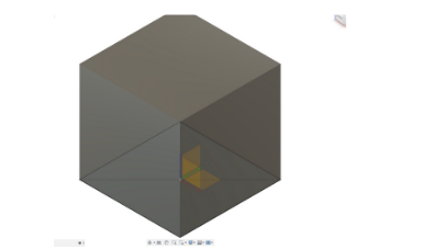 Extruded Hollow Cube
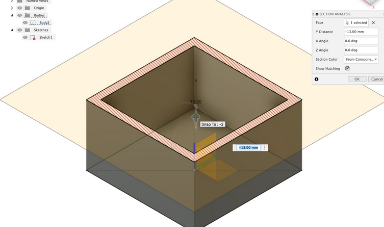 Section Analysis
 Rattler Component
 Print Interrupt to Put Rattler
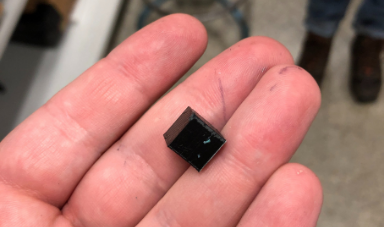 Final Shaker Cube
3D Scanning
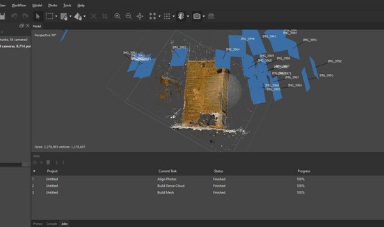
For the 3D Scanning section I ran into quit a bit of difficulty to get a well scanned model. I decided to use the software Agisoft, a photogrammetric processor. It works by importing in multiple photos and a video, and capturing key points in each of the uploaded images. It then attempts to line up the points accross the images to get an idea of the orientation that each photo was taken at. It can then create a density cloud to add more points to get more information now that the photos are aligned. Finally a mesh can be constructed of the object that can be exported as an STL or OBJ. In our case I took a about 50 photos of a box of cornstarch from various different angles. Then they were imported into Agisoft, and were aligned, which took about 20 minutes. A bit over half the photos were properly aligned. Following a density cloud was filled in, and then a mesh was constructed. The end result was very mediocre, and this is propably due to poor photos, but this was our third attempt and we were running out of time unfortunatly to try again. In addition the software would not take in the video file, which may be due to being in a .MOV format. and it would be wroth to try again as a more standardized format.
For the 3D Scanning section I ran into quit a bit of difficulty to get a well scanned model. I decided to use the software Agisoft, a photogrammetric processor. It works by importing in multiple photos and a video, and capturing key points in each of the uploaded images. It then attempts to line up the points accross the images to get an idea of the orientation that each photo was taken at. It can then create a density cloud to add more points to get more information now that the photos are aligned. Finally a mesh can be constructed of the object that can be exported as an STL or OBJ. In our case I took a about 50 photos of a box of cornstarch from various different angles. Then they were imported into Agisoft, and were aligned, which took about 20 minutes. A bit over half the photos were properly aligned. Following a density cloud was filled in, and then a mesh was constructed. The end result was very mediocre, and this is propably due to poor photos, but this was our third attempt and we were running out of time unfortunatly to try again. In addition the software would not take in the video file, which may be due to being in a .MOV format. and it would be wroth to try again as a more standardized format.
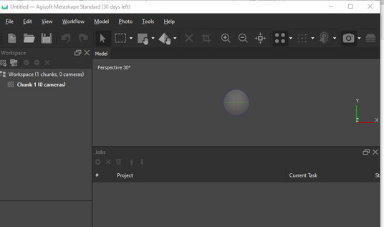 Agisoft Home Screen
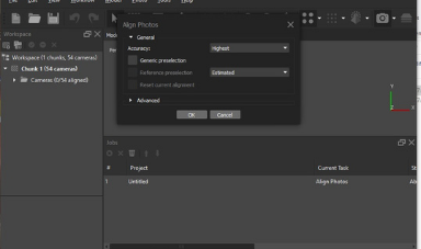 Aligh Photos Settings
 Corn Starch Model Photo Example
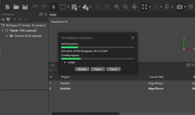 Aligning Photos Progress Bar
 Constructed Mesh
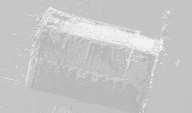 Final STL
Click Here to Download all the files from these projects!