Jacob Libby
Week 12
Output Devices
A week dedicated to learning about outputs and solidifying knowledge of circuitry
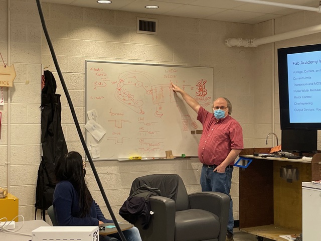
We began this week with the group project of exploring the ins and outs of outputs, going over the different types of outputs and analyzing them with an oscilloscope. In this lab, we looked into voltage, current, power, current limits, and then moved more towards hardware. We looked at mosfets and transistors, motors, and even learned about Charlieplexing (a super cool way to hook up outputs to limit the amount of pins).
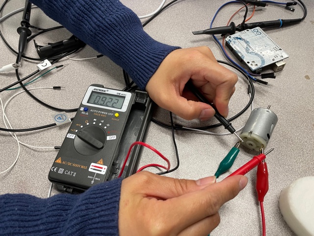
One of the coolest part of the lab, we looked at motors and found out the minimum amount of voltage needed to power it. This was a neat look into the requirements of output devices, and made me start to think more about how such requirements could come into play with my final project. We then tried to keep the motor stationary and saw that the current increased and the voltage decreased. This was backwards to what I was thinking would happen, since I imagined the "pipe" getting more pressurized since the electrons had nowhere to go and it was really educational to interact with it and discover the opposite hands-on.
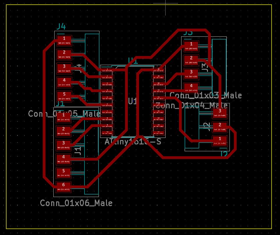
Since the individual assignment was again to mill, solder, and make a new board, I started by designing a board right away that I could attach an OLED display and a joystick to. I was hoping to use either a rotary encoder or a joystick, and later down the line found that rotary encoders were very difficult to ensure accurate readings of direction and were (in my opinion) too unreliable.
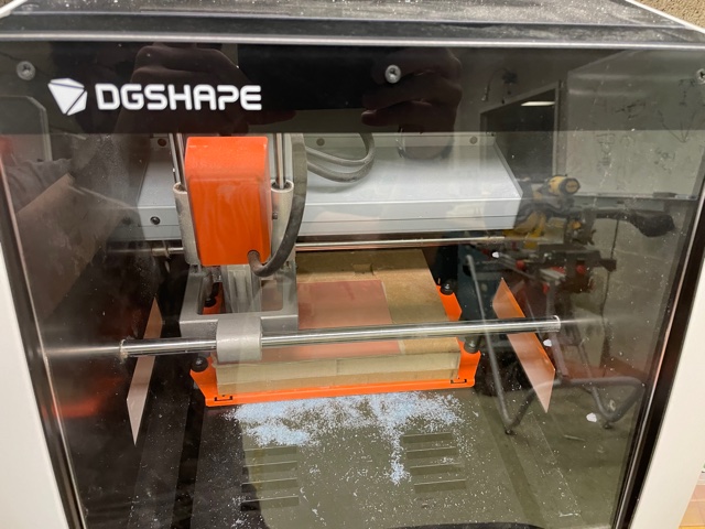
I started the cut and immediately noticed that the Roland was once again acting up.
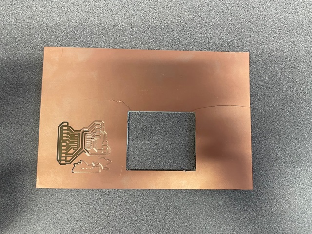
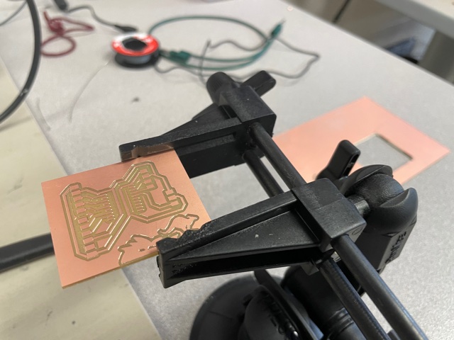
On the left, you can see that even after numerous attempts of re-zeroing the machine, restarting the cuts, lowering the z, and so on and so forth, the leftmost edges of the cut were cutting super thin traces while the right side barely etched into the material. I looked over mods and didnt notice anything wrong, so I set the cut to cut again in the middle of the material this time, and it turned out well. While removing the cut from the bed, the material snapped slightly, but c'est la vie.
I then began the process of soldering.
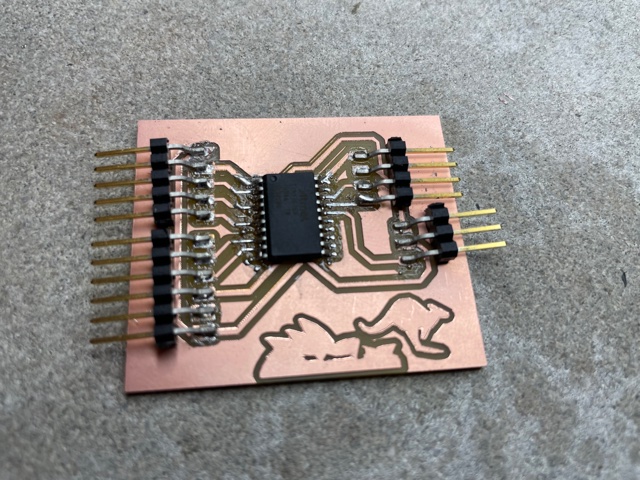
The first round of soldering did not take too long, however after getting UPDI errors and poor connections, I had to keep resoldering the ATTiny1616 down again and again, which made the board look a little burnt, but surprisingly did not break anything further.
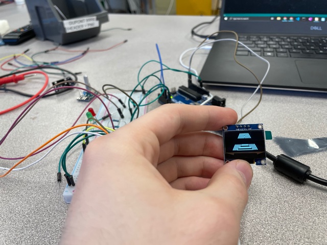
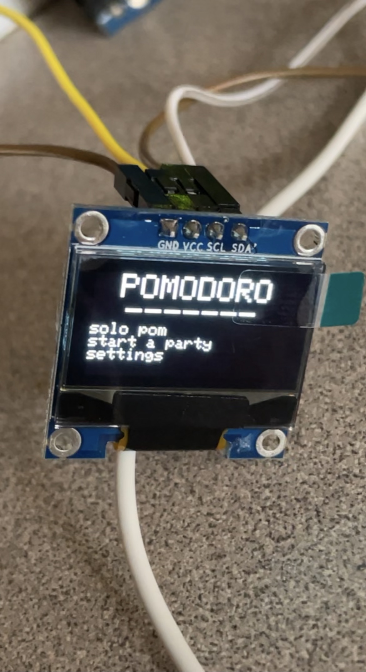
I then, with the help of Professor Goodman, set up a breadboard to test out the rotary encoder in order to figure out how it works. After taking a very long time to better understand it, I moved on to the OLED display and got the example code running!
After continuing to tinker and tinker with the code, facing far more issues than I had hoped, I got the code running, and even included a small count in the top left of the screen that would increment/decrement along with the user turning the rotary encoder.