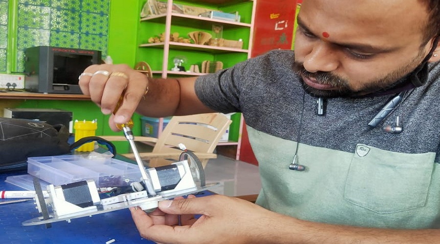
Week ninth is the Machine week.In this week we have to make a machine which is not only design mechanically but actually working according to the condition/commond given to it without physical supports.In this week we have to completed our group work first and the individual one.We are much excited about "Machine week".
Assignment-9
Mechanical Design, Machine Design
OBJECTIVES
Group assignment
- Design a machine that includes mechanism,actuation,automation
- Build the mechanical parts and operate it manually.
- Actuate and automate your machine.
- Document the group project
Individual assignments
- Document your individual contribution.
Learning outcomes
- Work and communicate effectively in a team and independently
- Design, plan and build a system
- Analyse and solve technical problems
- Recognise opportunities for improvements in the design
About Group Assignment
This week assignment is divided in to two parts Mechanical design and Machine Design. The objective of the mechanical design involves mechanism (a system of parts working together in a machine) + actuation (the action of causing a machine or device to operate) + automation (the use as automatic equipment). The objective of the machine design involves a actuate (to move to action a decision) and automate (a fully automated process) the design machine.In starting lacture of the machine week Neil had introduced us about diffrent mechanism for machine design also focuesd on the examples of previously design machines.With this motivation we had started for machine week.
As team sprite we were trying to for novel ideas for machine like Caroom board player,Ragoli making machine with multi color,Arm robo,Hand router etc.With the idea of hand router(Shaper) we decided that we design a machine which had multiple application just by changing replacing one axis and there is no boundary limit for its working space.With this we introduced "चित्रCar" (Chitracar)the sketcher.
About "चित्रCar"
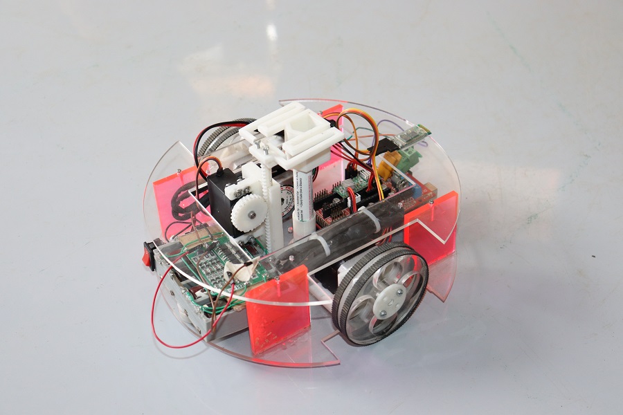
"चित्रCar" is a machice which sketch the given object as per commond line with out limit of boundary. its wheel are woked as X-Y axes and the Z axis is act as main axis.Initally we uesd Maker pen for drawing the different shapes working as sketcher.As per our idea we will replacd the Z axis assembly for its different spryals like Ploter, Router etc.For more details click on "About Group assignment".
About Individual Assignment on Mechanical Design, Machine Design
As per our group decision ,my individual task is to design the X and Y axis of "चित्रCar" also design the the chassis. The workflow of individual work is as follows.
- Draw the Sketch of Different parts.
- Design and print the stepper bracket.
- Design and cutting the Wheel.
- Design and print the wheel connector.
- Print the marble caster wheel.
- Design the Chassis and test assembly.
- Assembling the components in CAD software.
- Actual assembling parts.
- Trail motion of X and Y axis.
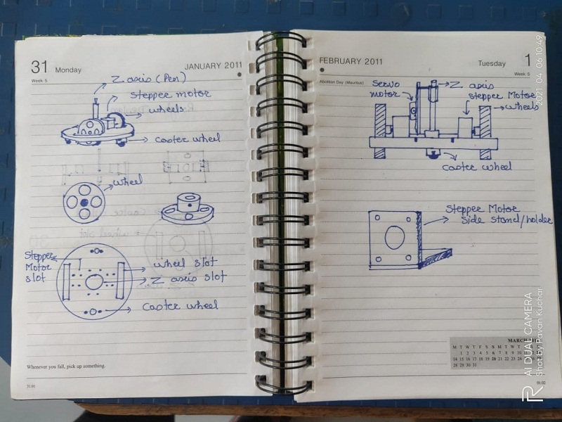
Draw the Sketch of Different parts.
The skech shows the main parts of the machine.The basic structure consist of circular shape Chassis,two stepper motor side brackets holder , two big wheels for the X-Y movement, two caster wheels for suppoert and balancing the assembly and ceneter Z axis assebmly for servo motor with pen holder.
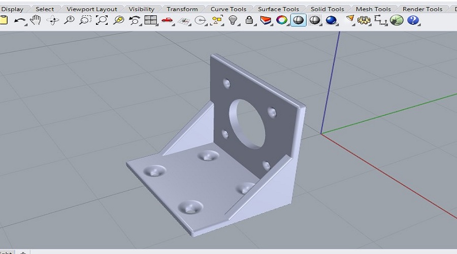
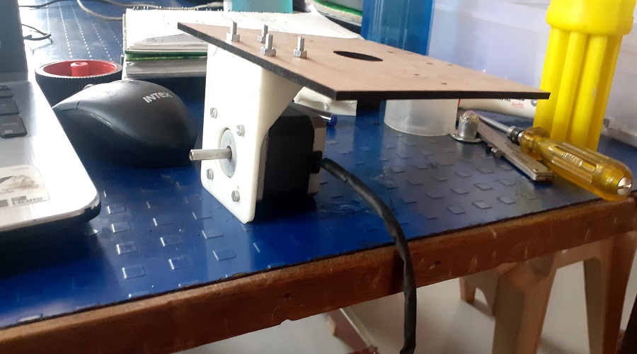
Design and print the stepper bracket.
For the X and Y movement we consider the Nema 17 stepper motor. For holding the stepper tried to design side brackets. For designing the brackets I use Rhino.6. for bracket design I have take the reference from Nema 17 datasheet .
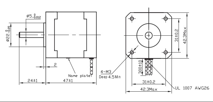
Dimension of Nema 17 Stepper motor.
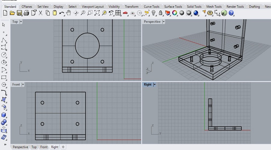
- Bracket design in Rhino.
- Solid view of Bracket.
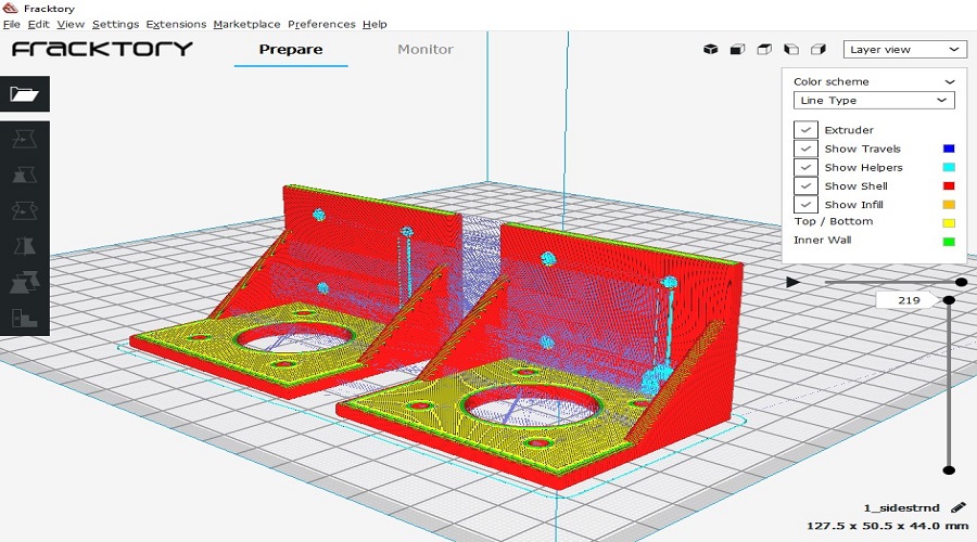
- Opening the .stl file of Bracket in the fracktory software for 3d printing G-code generation.
- The slicing image of pair of Brackects.
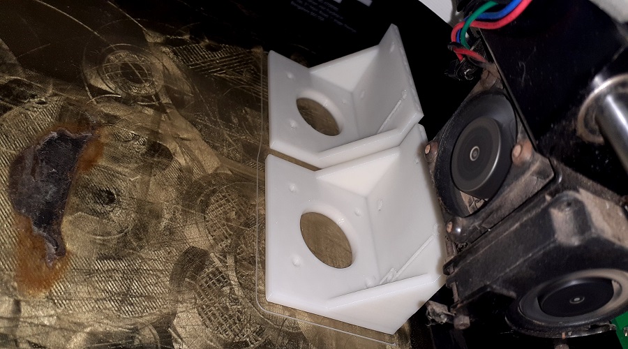
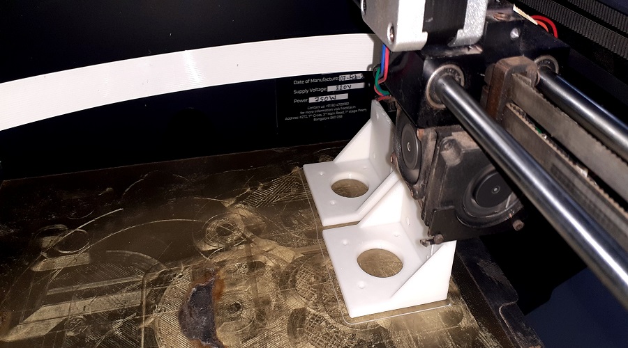
- Used Fracktal work 3D printer for printing.
- Image during printing the brackets.
.jpg)
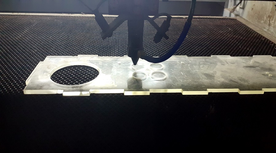
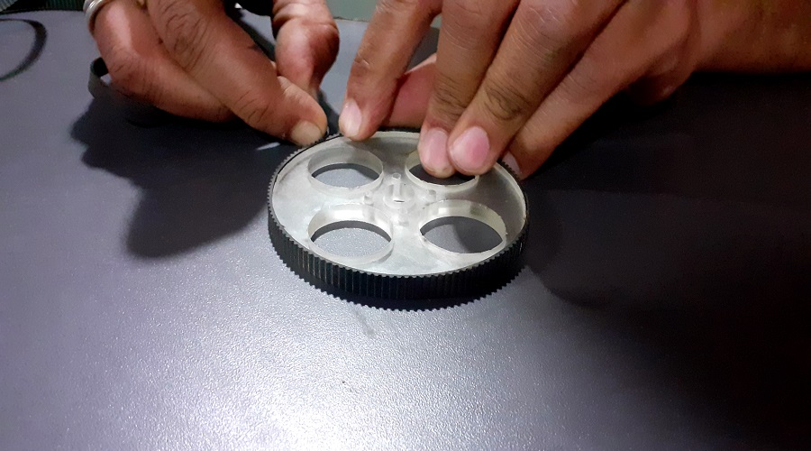
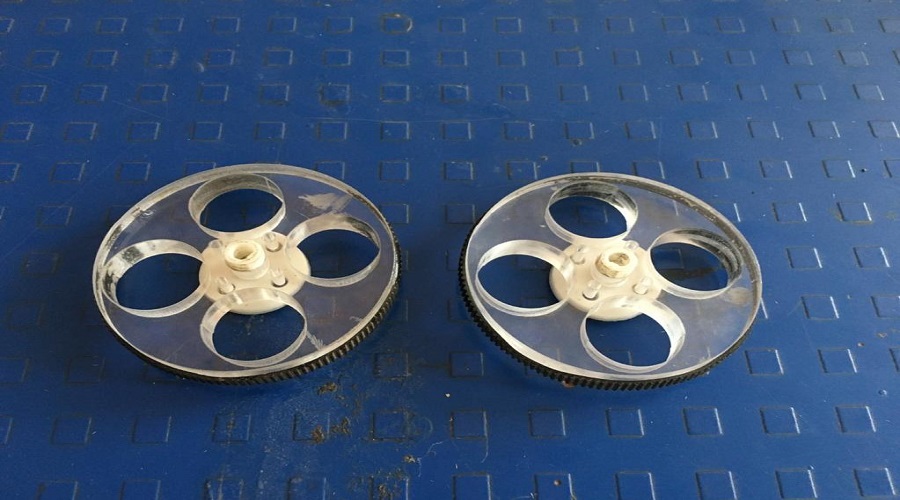
Design and cutting the Wheel.
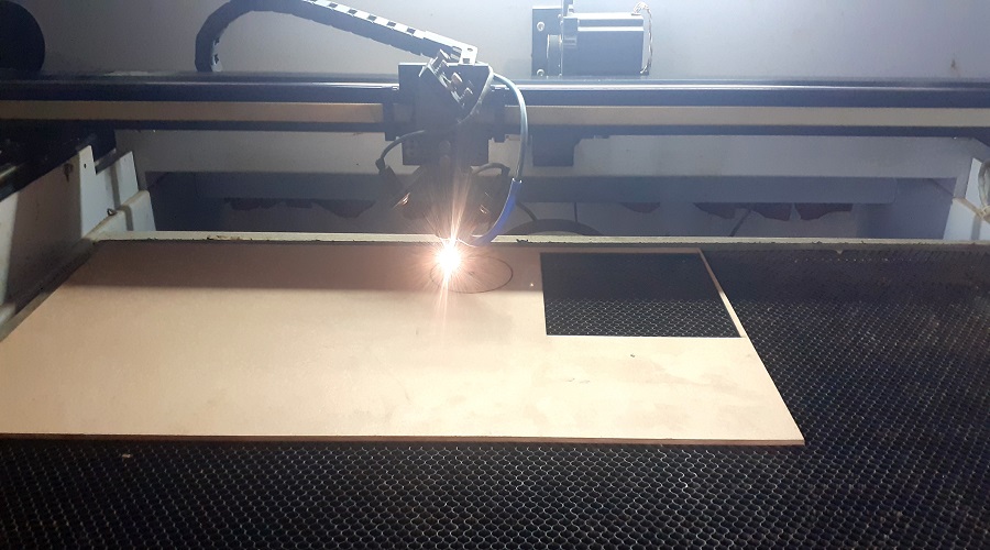
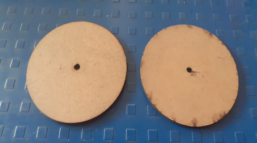
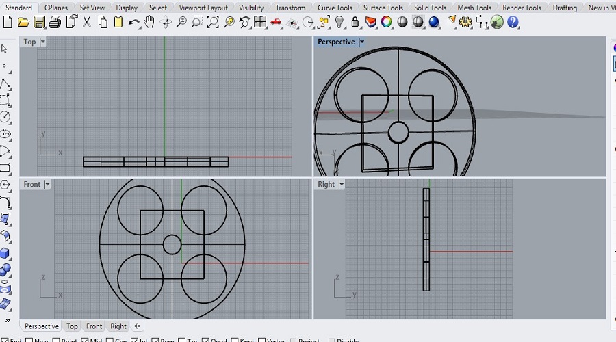
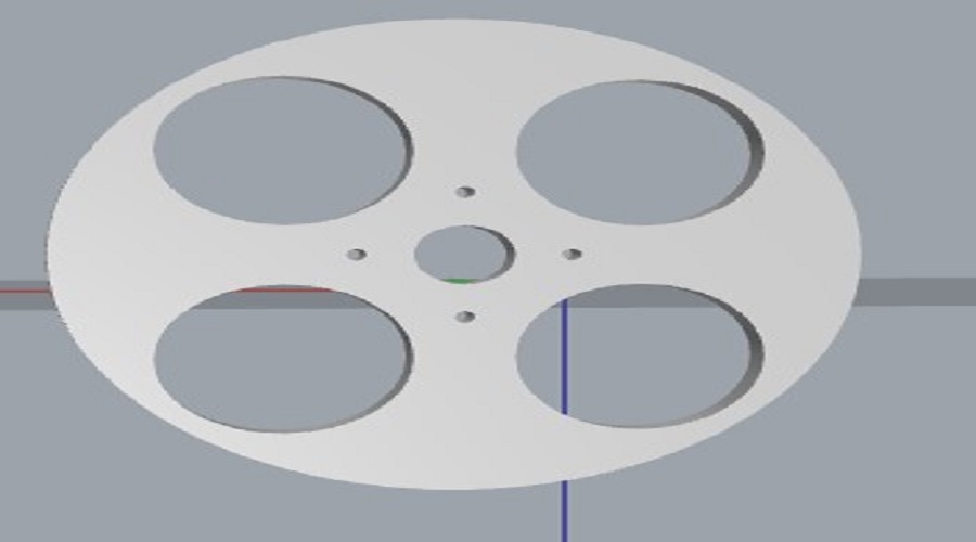
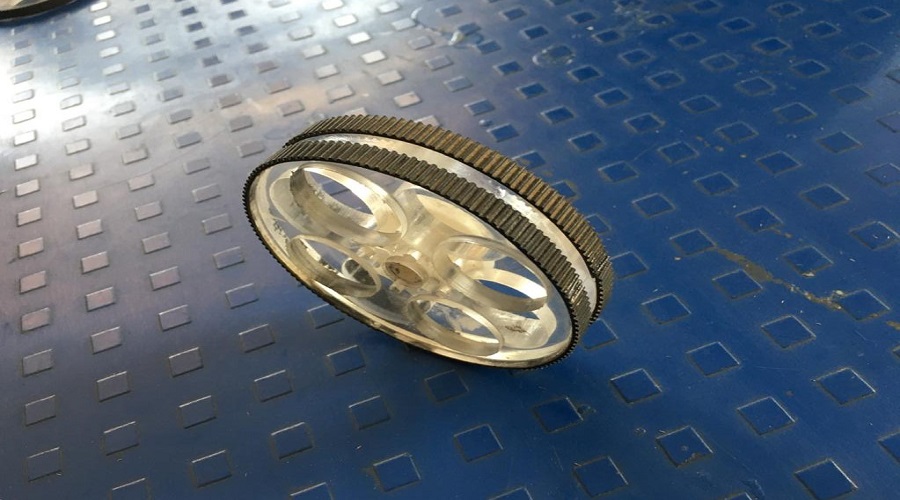
For wheel Initially take MDF material , consider the simple 2d circle shape and cutting with help of Laser cutter.After trying the MDF we decided that the Acrylic wheel for our machine. Now I have design the a wheel in the Rhino.For its aesthitic consider four circle which also reduced its weight.Now conerting the file in the dxf file and used laser cutter for cutting. Once the wheels are cut, we observed tha the cutting edge of wheel is smooth and we are in need of rough one for friction and grip.Initially tried for rubber band but it does not working properly and the idea come. We are having pieces of Timing belt in our lab, we used this for better grip. Simply used the Timming belt stick on the rim. The acrylic wheel with timming belt is shown in the following images.
- Cuttung MDF using laser cutter.
- Cutting pieces of wheel
- Designing Wheel in Rhino.
- Solid view of Wheel.
- Cutting Acrylic wheel using Laser.
- Observing during laser cutting.
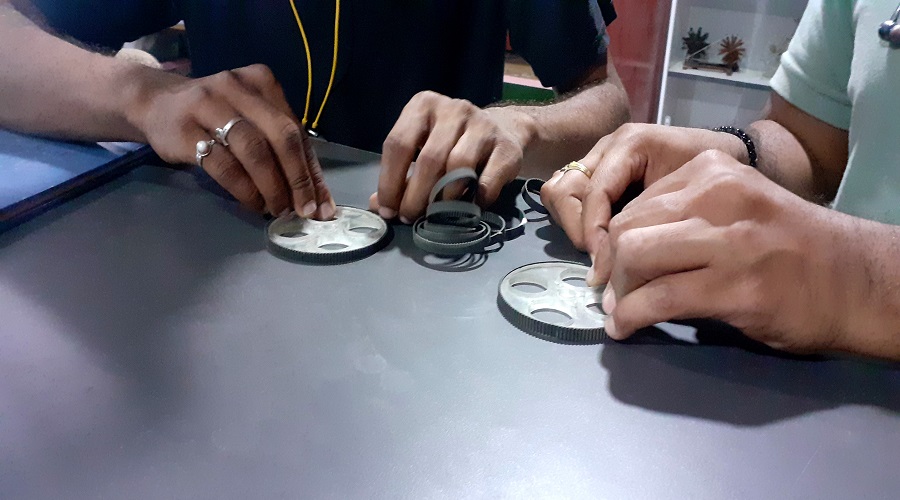
- Cutting timing belt a/c to the rim of wheel.
- Apply the timing belt along the rim of wheel.
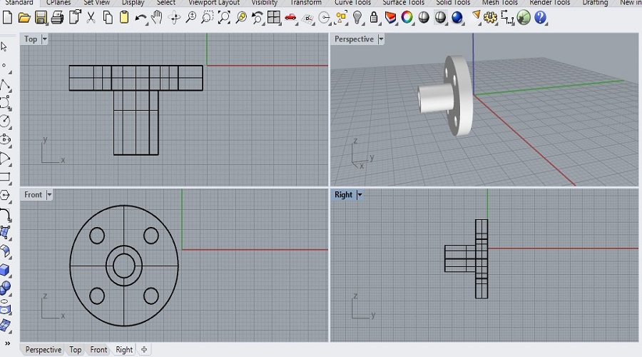
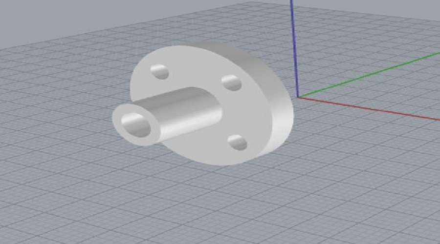
Design and print the wheel connector.
After design and cutting the wheels on the laser cutter I found that ,wheels are not directly attached to the stepper spindle. With the stepper motor vibration the wheels were dropout from the spindle. To avoid this we design the wheel connector and print it with 3D printer.For designing the wheel connector used Rhino. The wheel connector holds the wheel properly with the stepper with proper motion.
- Designing Wheel connector in Rhino.
- Solid view of connector.
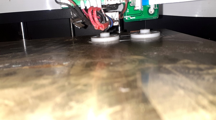
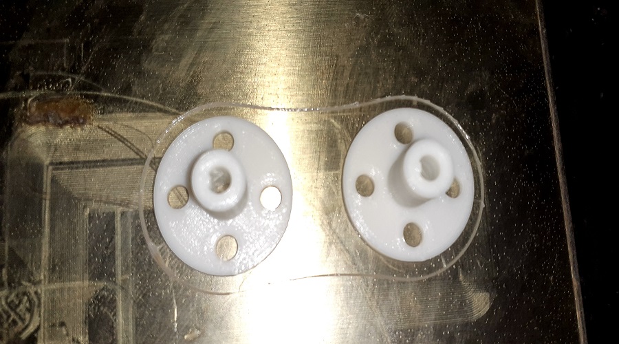
- Used Fracktral work 3D printer for printing the Connector.
- 3D printed Wheel connector.
Print the marble caster wheel.
For our machine we used the metal ball caster wheel. Its benefit is that it maintain the ground clearance as well as balance the machine body. While using the metal caster wheel one of the wheel was not working properly. We were trying for alternative and got the idea of marble caster wheel.For this used the reference of thingiverse for marble caster wheel design marble caster wheel design.Purches marbles from local and print the caster wheel by 3D printer.
- Printed caster wheels
- Caster wheels with marble.


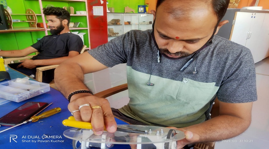
Design the Chassis and test assembly.
Initially we have tried for the square shape chassis using MDF material. Cut with the laser cutter and tried to assembled it.with this square shape all the components were places very closed to each other also the machine was not balance properly. So we were moving to the simply strong shape that is circular shape. We tried it firstly for MDF with proper assembly. The acrylic material used for final chassis.
- Connecting the stepper motor to the square shape chassis.
- With stepper connection few space remains for other components.
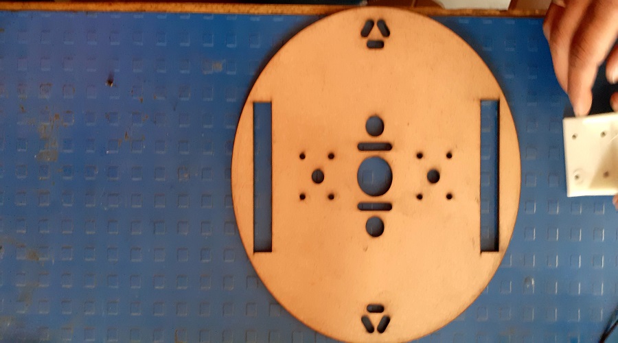
- Circular Shape MDF chassis.
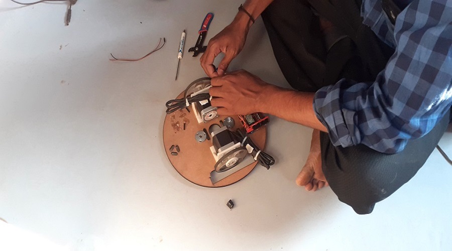
- Mounting all the components on the chassis.
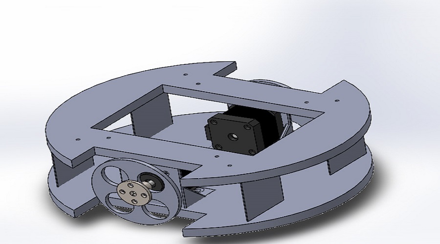
Assembling the components in CAD software.
Tried to assembled all the components in the Rahino.6 but in we are unable to take the 3D shape of Stepper motor in Rahino.so we used the Solid works for assembling the parts with the help of Miss Pooja our Fab lab supervisor.The assembly images are given below.
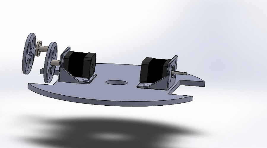
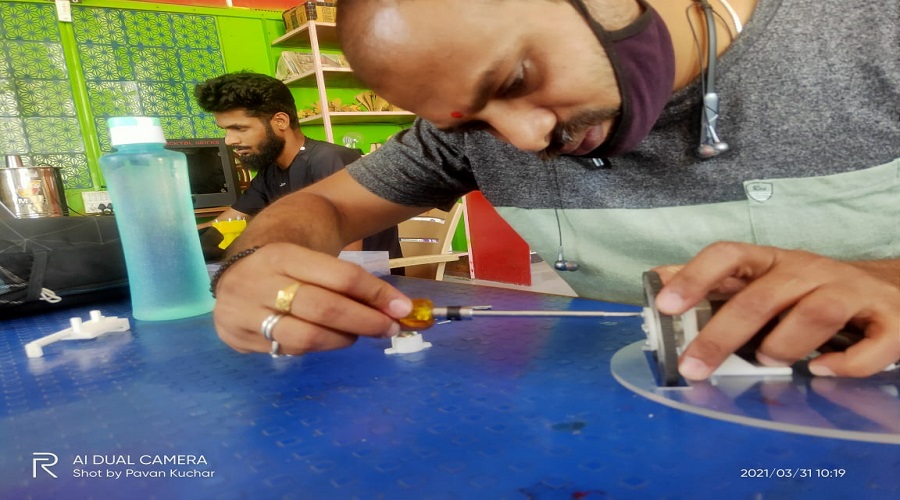
Actual assembly.
The actual assembly of all the parts that I have mention above is given the following images.
- Connecting Wheels to the steppe motor.
- Mounting stepper motor on the design chassis.
- Connecting caster wheel to the chassis.
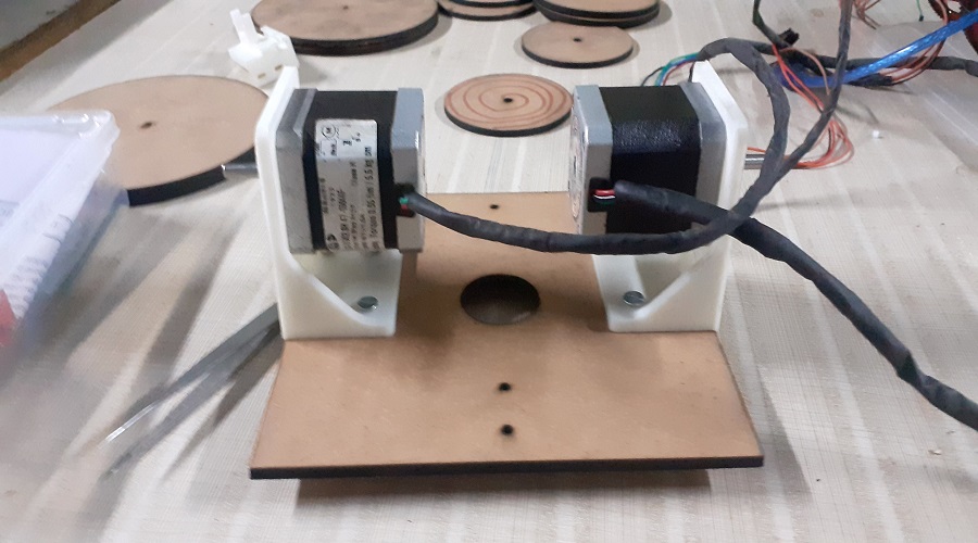
- The assembly of stepper motor (X & Y axis) with caster wheel.
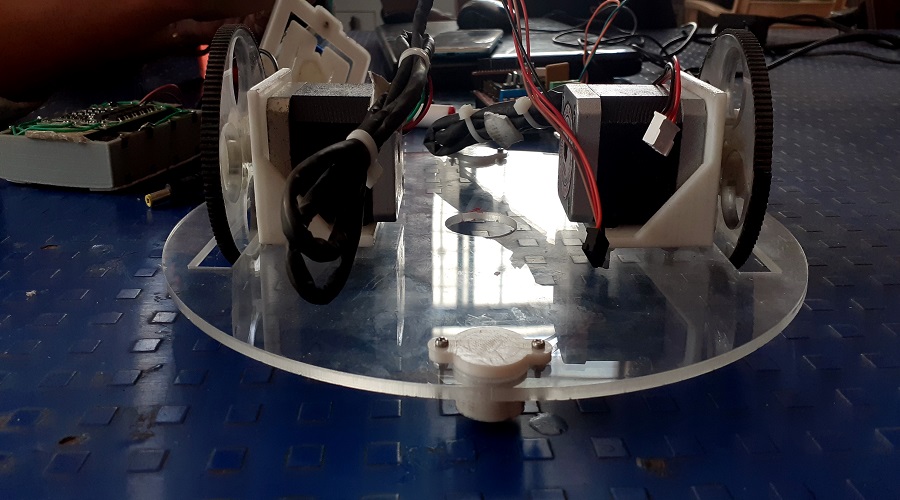
The Final assembly of "चित्रCar" (Chitracar)
Trail motion of X and Y axis.
Problem Faced/Solution provided.
It is observed that during the motoin the wheels not get proper grip.So for increasing the grip we used another 12mm thick Acrylic wheels and attached with old one, also we have to cut the edge for fixing of wheels shown in the final assembly of Chitrakar.The modified wheel image is given below.
Downloads
SAMS-Smart Azolla Multiplier System by Anand S. Tale is licensed under CC BY-SA 4.0![]()
![]()
![]()