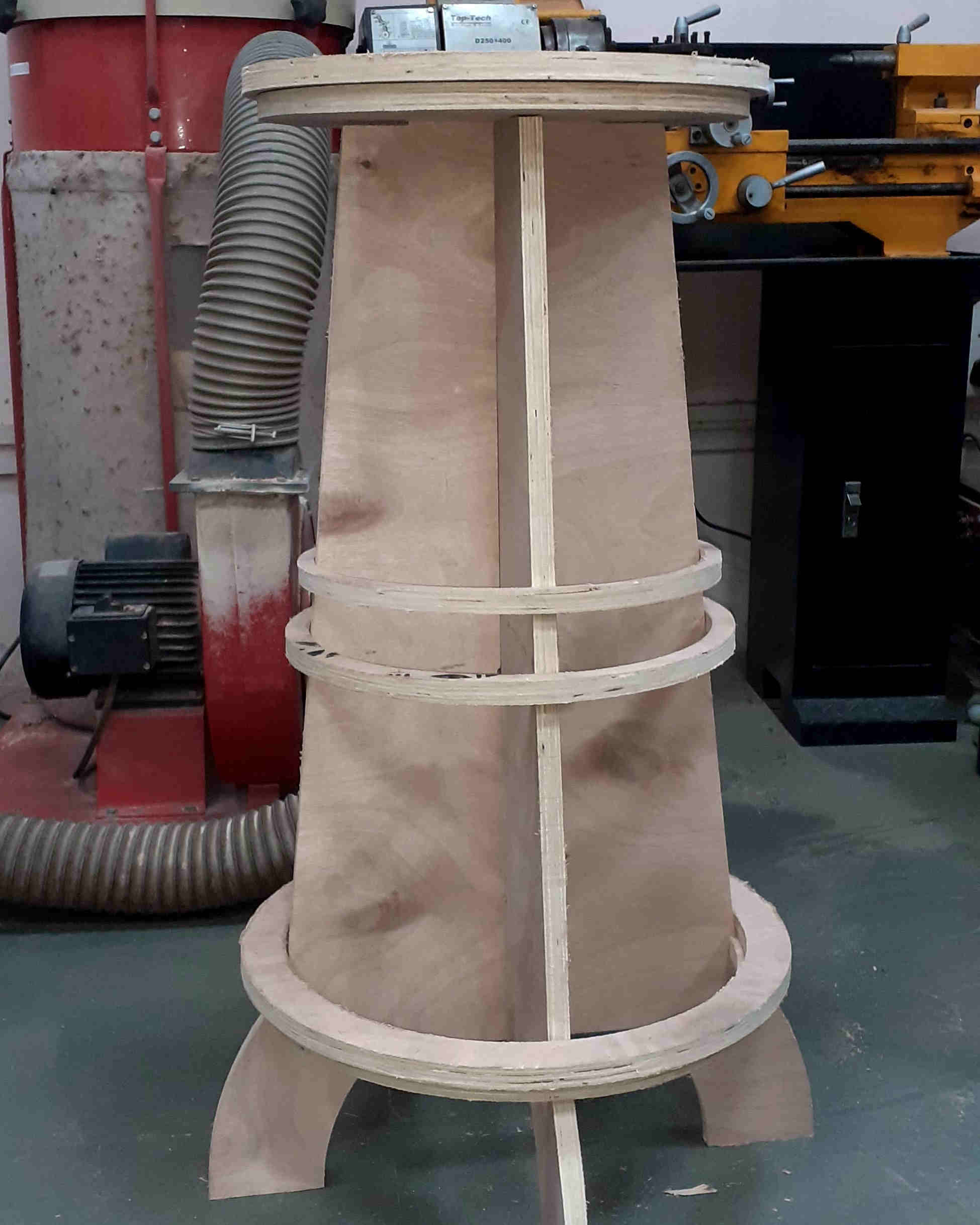
Seventh week is also creative week but in this week we have to design something big(Wooden Furniture)and cut it by the CNC mahine from COEP.Uesd the partworks software for toolpath generation.Due to COVID-19 issue we remotely accessed the partwork software.I have design High Stul for this week assignment.
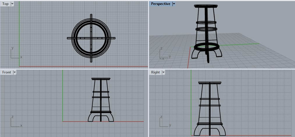
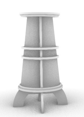
Hero shot
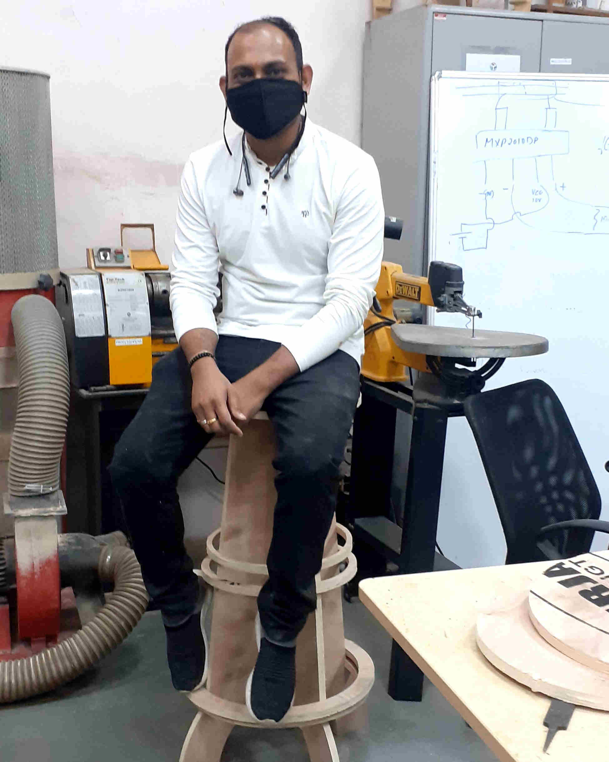
Hero shot
Assignment-7
Computer-Controlled Machining
OBJECTIVES
Group assignment
- Test runout, alignment, speeds, feeds, and toolpaths for your machine
- Document your work (in a group or individually)
Individual assignments
- Make (design+mill+assemble) something big
Learning outcomes
- Demonstrate 2D design development for CNC production
- Describe workflows for CNC production
About Group Assignment
In group assignment we have to check milling rules for Shopbot CNC Machine. For that different test patterns likeo test runout, alignment, speeds, feeds, and toolpaths are given in the assignment.Also safety paramerters which plays important roll while operating the CNC machine.For Shop Bot assignment we use the COEP lab but due to COVID we remotely access the S/W rquired and try to generate the tool path by any Desk tool.
Safety and Precautions
- Learn and understand safe use of the machine. Do not allow untrained individuals to operate the machine without supervision.
- Eye and ear protection MUST be worn by the machine operator as well as any bystanders or observers
- Wear closed-toe shoes at all times.
- Make sure that your material is properly secured before cutting, and be aware of any small parts that may come loose after being cut.
- Never place your hands on the rails of the ShopBot.
- Wear gloves while operating the machine.
- Never leave a machine running and unattended. Understand that a spinning tool generates friction and heat, creating a risk of fire.
- Keep a working fire extinguisher within reach of the machine
Individual assignment on Computer-Controlled Machining
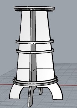
In week we have to design furniture by using Shopbot CNC machine.as per discussion with instructor the design furniture must be useful for its intended purpose.so I decide to design High stul for soldering station and also for operating Numac machine in our FAB lab.I used Rhino for design the stul.The work flow for the assignment is as follows
- what is cnc?
- About Shop Bot
- Design an object in Rhino.6
- About Joints
- About Partworks S/W
- Step for generating Tool Path
- Machining on Shop Bot
- Assembing Parts
What is CNC?
A CNC (computer numeric control) tool is used in prototyping and full production for cutting, carving, machining and milling in a variety of materials including wood, mdf, plastics, foams and aluminum. (Source:3D printing)
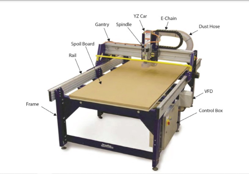
About Shop Bot CNC Machine
With a ShopBot CNC tool, you use the included software to design your parts on your personal computer, then, like a robot, the computer controls the cutter to precisely cut your parts. In the past, CNC tools were strictly industrial tools only used in large factory settings. Now, all the types of computer-driven tools that create things by cutting material away (such as CNCs or laser cutters) or building up material in layers to create an object (3D printing) are called digital fabrication tools. ShopBot's innovations in CNC technology have made these powerful tools affordable for individuals and small shops. (Source:Shopbot)
Features
- Fast, closed-loop Vexta alphaStep motors fitted with low-backlash, tapered-hob gear heads on all three axes (two on the X axis) -- alphaStep system monitors motor shaft positions to maintain synchronicity between signal and motion
- Tough precision linear bearings on the moving gantry and hardened steel rails for the x-axis.
- Reliable rack-and-pinion power transmission on each axis.
- Impressive cutting speeds of up to 600 inches per minute (depending on cutting bit and material) and rapid transit speeds of 1,800 inches per minute.
- Step resolution of .0004”.
- Positional accuracy of +/- .002”.
- Sealed Industrial UL Certified Control Box.
- Emergency Stop disconnect switch in the Control Box with integrated and cabled remote Emergency Stop Buttons.
- Z-zero Touch-Off Plate and XY Proximity Switches.
- ShopBot Control System software to run your CNC.
Specifications
- XY Move Speed:Variable, max. 600”/min
- Z Move Speed:Variable, max. 360”/min.
- XY Positioning Speed:Variable, max. 1800”/min.
- Z Positioning Speed:Variable, max. 900”/min.
- Step Resolution:0.0005”
- Positional Accuracy (no load): +/- 0.003in
- Linear Cutting Force :Approximately 150 lbs.
- Input Voltage :110 volt (30 amp); or 220 volt (15 amp) [Single phase, 50-60Hz]
How ShopBot CNC works?
ShopBot Tools, like all CNC tools, move a cutter around a big table (X and Y axes) and move it up and down as well (Z axis) allowing it to make 3D movements and cut all sorts of shapes. The cutter looks like a drill bit and is spun by a motor called a router or spindle.Unlike a drill bit, a router bit is designed to cut from the sides as well as the tip. By precisely moving the cutter through material, a ShopBot CNC tool can create virtually any pattern or shape and will do it in materials such as wood, plastic, foam, aluminum and many composites(Source:Shopbot:what is CNC)
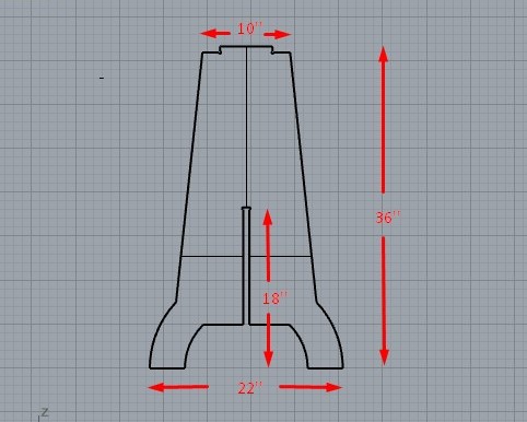
Object design using Rhino.6
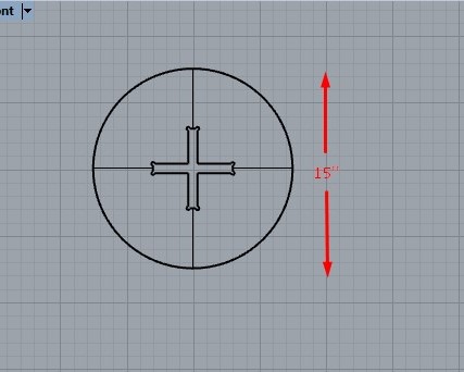
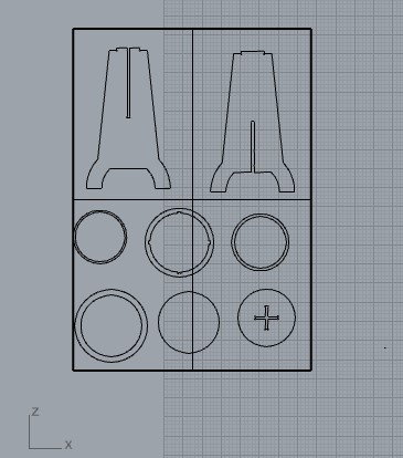
- Using Rhino.6 I have design the different parts of the stul as shown in images.
- Assembling all the parts of the stul in S/W.
Boby of the Stul
Top of the Stul
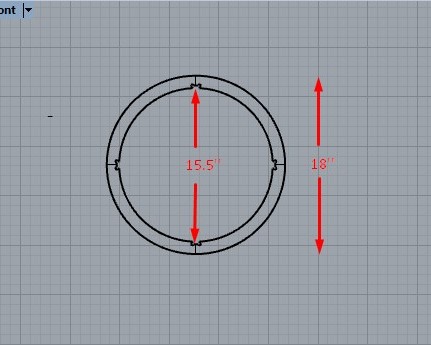
Bottom Ring of the stul
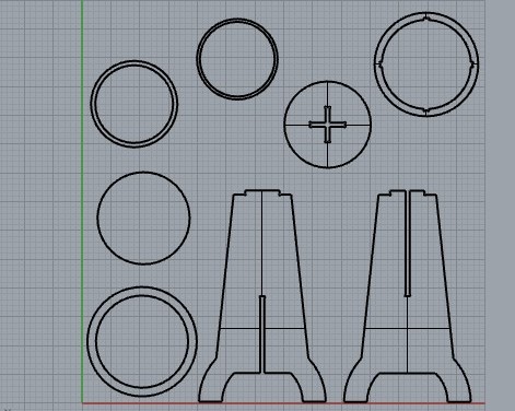
All the parts of the stul
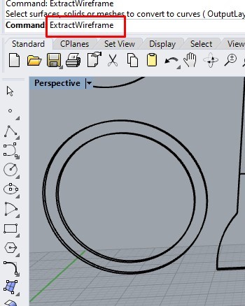
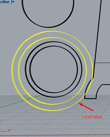
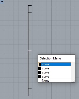
- Applying extractwireframe command on command line.
- Select an object,with enter extrct its wireframe.
- Delete the unwanted wire frame.
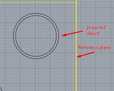
- Create a reference plan where you have to project the object.
- Select the object applying project command, select the plan. press enter, 2d object projected on the plan.
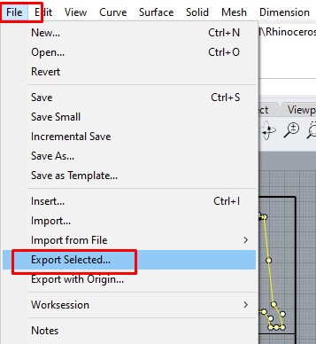
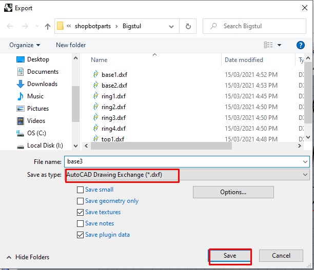
- Now for creating 2d vector image select an object. goto the file click on export selected
- save the file as Autocad drawing exchange(.dxf)
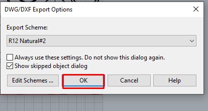
- DWG/DXF export option is open click ok. 2d vector file is created.
- with the same process create the 2d vector file of all the objects.
About Joint Fillet
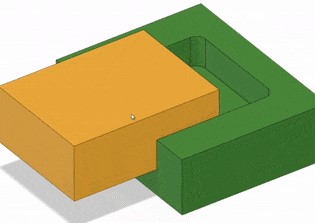
Normally fillet is used to reduce the sharpness of corners.the Fillet command takes two edges (line segments) and converts the corner into an arc.This is because the router bits are round. It is not possible to get orthogonal corners at perfect right angles when cutting out the sheet materials like MDF or plywood with a CNC machine, so instead, these corners will be rounded inwards.Due to this part tooled might not fit in the formed hole or slot.best solution on this problem is the Dogbone fillet.
Dog Bone Fillet
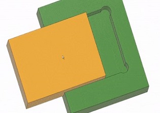
The DogBone fillet is different to a normal fillet because it creates a circular arc that is outside of the edges. The point of intersection for both edges is actually the mid-point of the arc.this fillet is like dogbone hence called Dogbone fillet.By introducing DogBone Fillets, the object fits better into the slot.
Normal fillet
Dog Bone fillet
About Partworks S/W
PartWorks is a CAD/CAM program that will get you started quickly designing for CNC cutting and machining. This 2.5D design system has a highly acclaimed interface that makes it easy to get your ideas and designs ready for your ShopBot to cut.In addition to doing great cutting of 2D parts, PartWorks has excellent capabilities for 3D V-Carving (machining that gives letters and shapes a chiseled look; also referred to as Intaglio or 3D Engrave). It allows anyone with a ShopBot CNC tool to quickly and easily incorporate beautiful, decorative carved designs into their own products.
PartWorks comes with the ability to V-carve any fonts on your computer as well as closed shapes. It also includes advanced machining strategies for large areas and difficult to machine patterns.( source:Google)
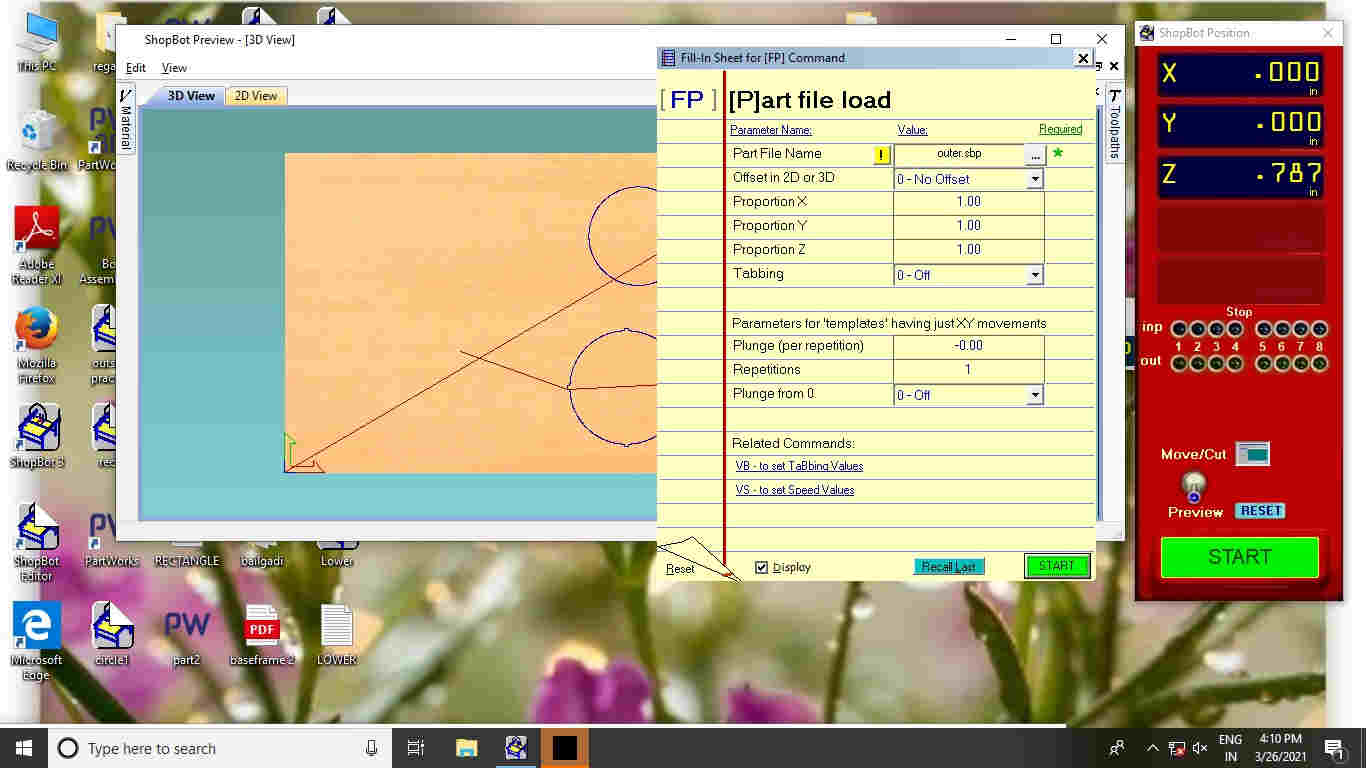
Step for generating Tool Path
Due to covid issue we remetely access the Part works S/W and tried to generate the tool path.
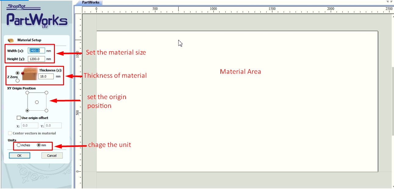
- Open the part work software.the opening window is as shown in the image
- An opening window consist of material setup
- set the width(X) and height(Y) of material
- Set the thickness of material(Z)
- Set the origin where imported object is placed
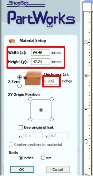
- Change the unit in mm or inches
- I have set the parameters in inches.
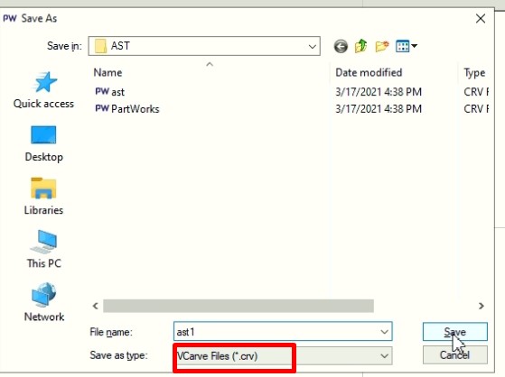
- Go to file menu and save the file as VCarve files(.crv)
- Click on ok, next partwork window interface is opened with different operations
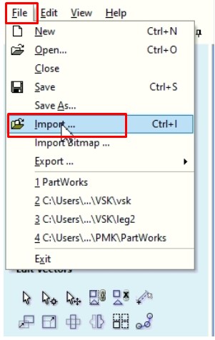
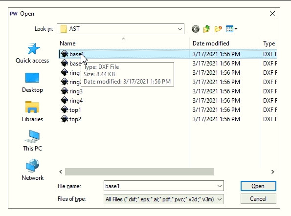
- Goto file and import the object
- select the object dxf file imorted in the part works
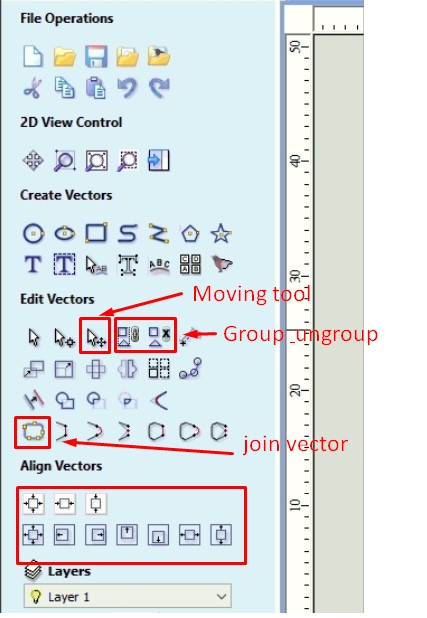
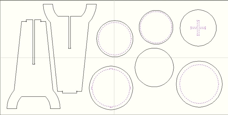
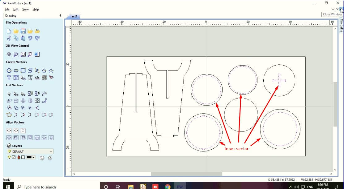
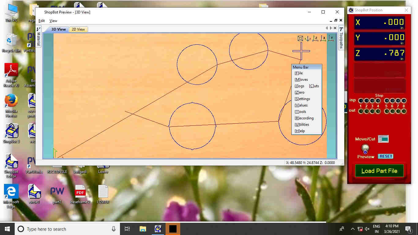
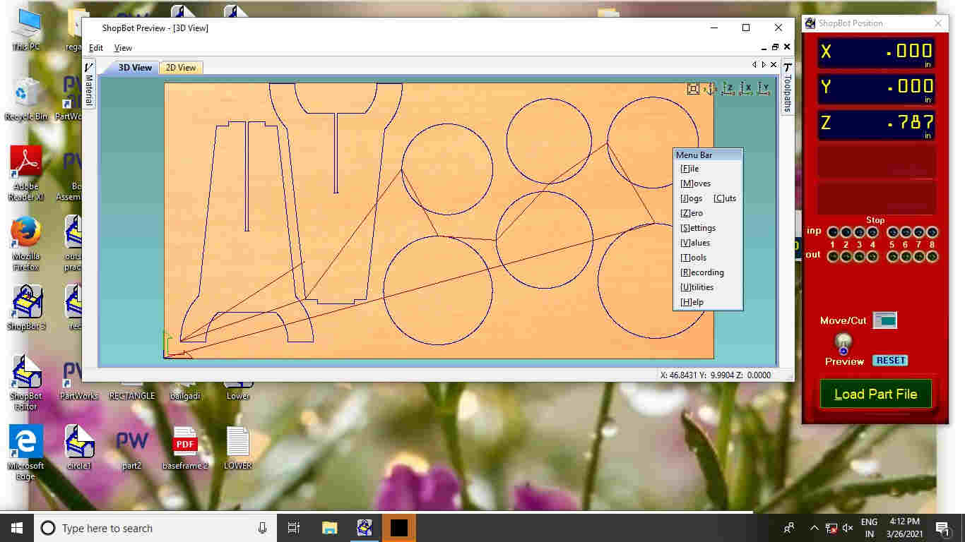
- Imported object are shown in the partworks.Arrange all the objects properly on the white background i.e cutting material with the help of move and rotate tool.
- Select an object check vectors are open or close by using vector join tool. If it is open join it with clicking on join closed it.
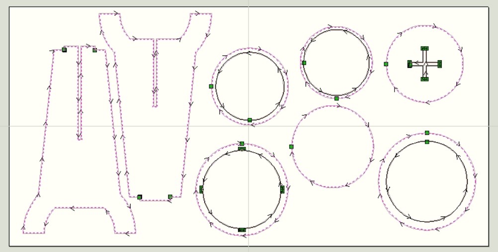
- Now select the inner part(inner vector) of all the objects you have to milled.
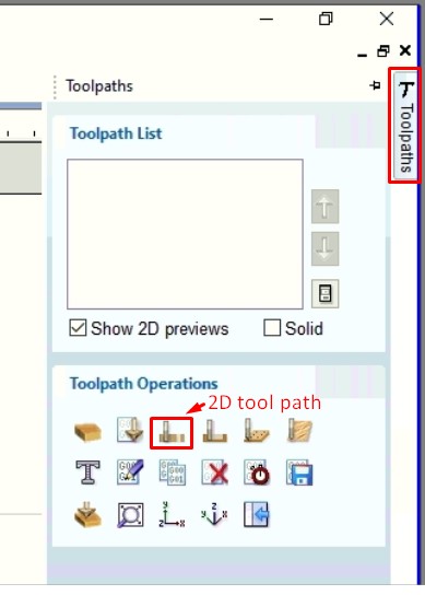
- Go to toolpath given on the top right corner of the screen as shown in the image.Goto the 2D profile tool path
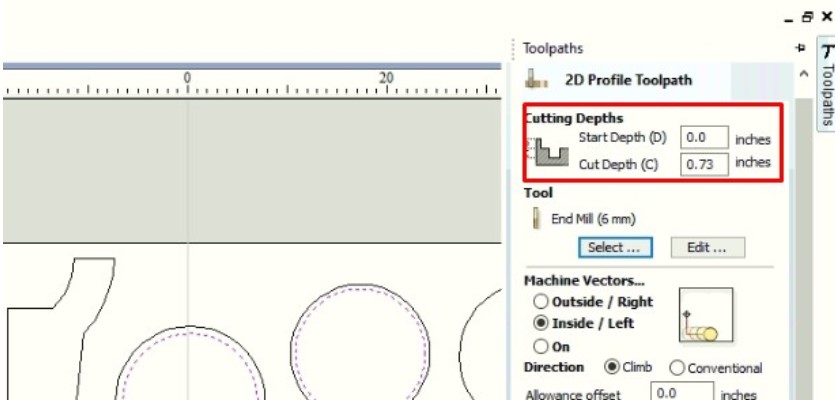
- Enter the start depth and cut depth. Note that cut depth is always greater than thickness of material provided sacrificial layer is available.
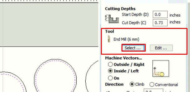
- In tool goto select. Tool data base is open.
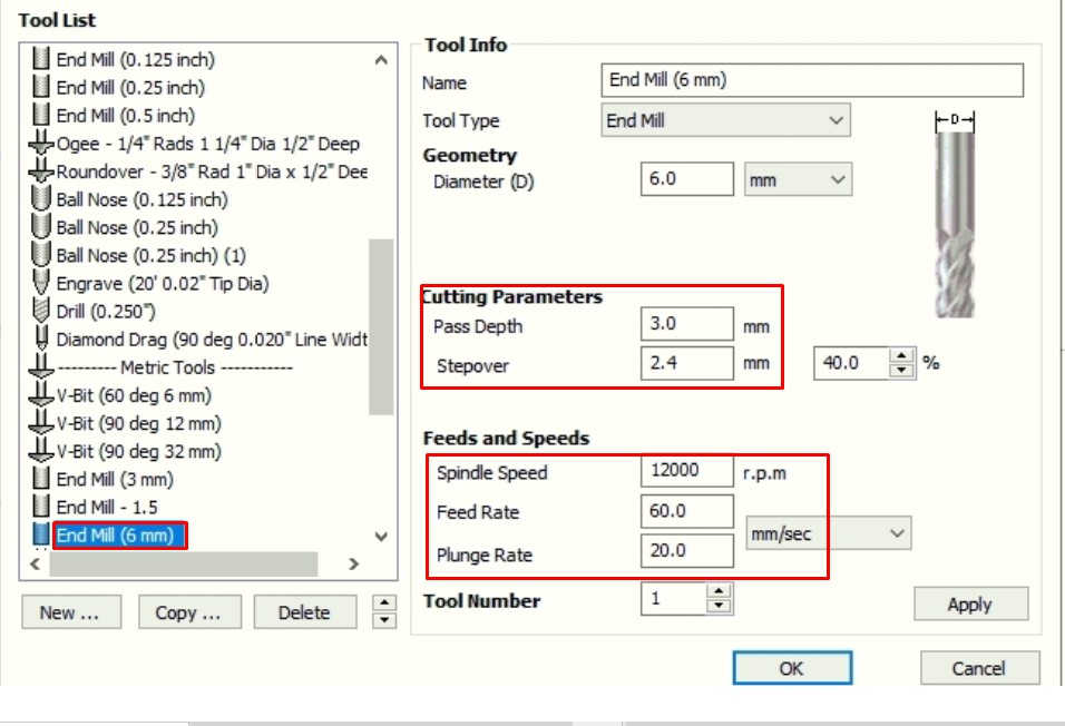
- Select end mill tool, check the cutting parameters,feeds, speeds and change accordingly but I set it default. Click apply and ok
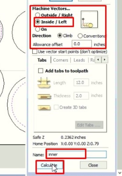
- In machine vector click on inside, name the profile inner click on calculate
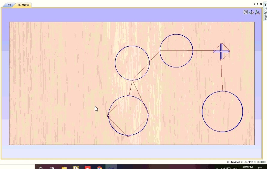
- The tool path is generated for inner vector cutting.
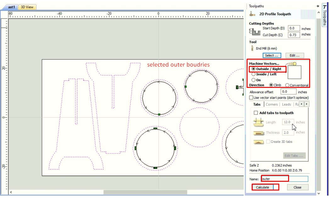
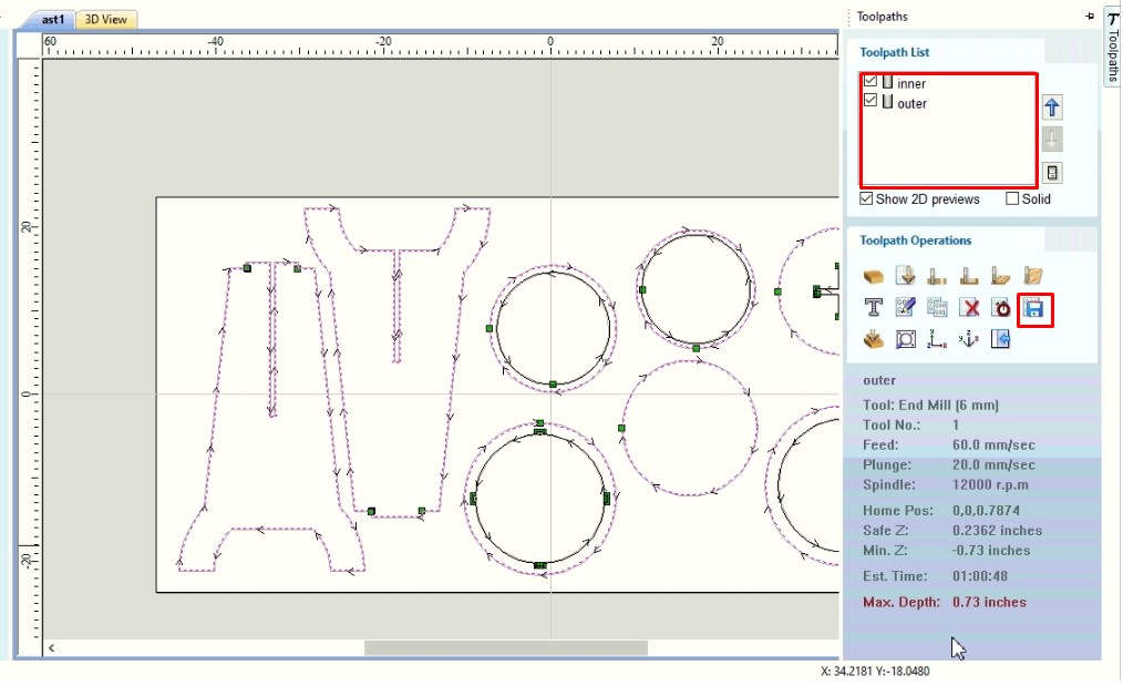
- Select outer boundary(outer vector) of all the objects goto the tool path. Go through the same procedure as given for inner vector only select outside in Machine vector. Name the profile outer click on calculate.
- the tool path is generated for outer vector cutting
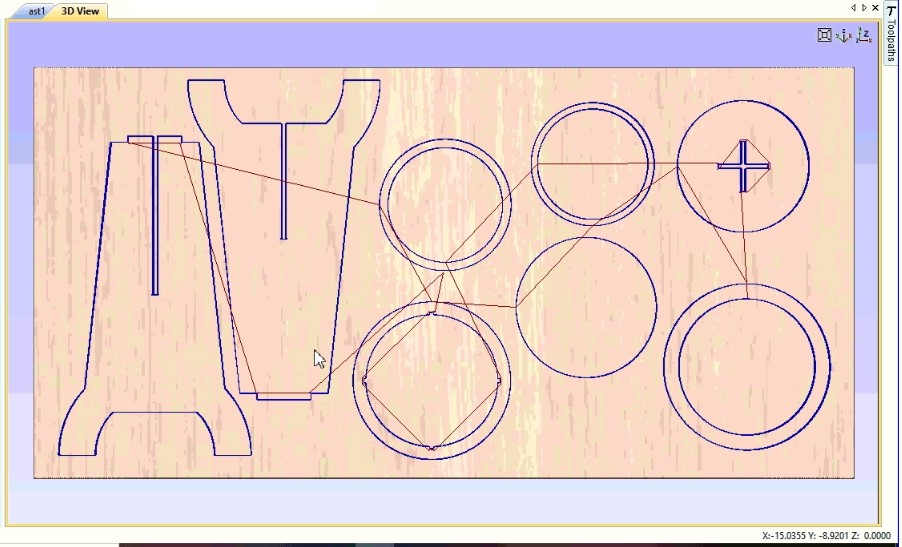
- Cutting tool path for Inner and outer vector.
- Save the tool path by using save tool path option.
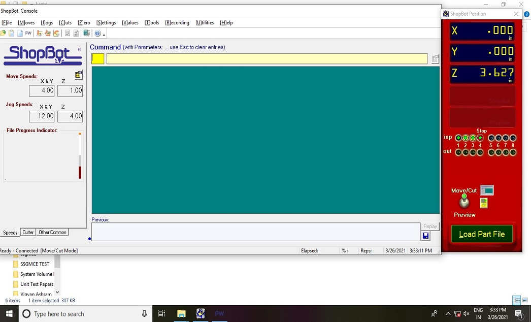
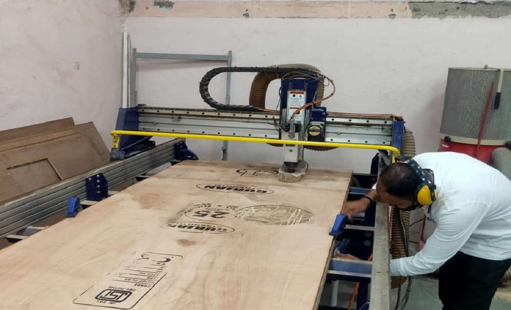
Machining on Shop Bot
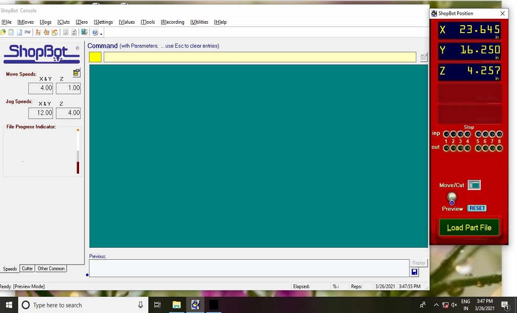
The opening window of Shopcontrol software is used to control the Shopbot CNC tool.By using its different commond we can move the tool and cut the object.It uses the .sbp file.
- The opening window of Shopcontrol software is shown in the image.
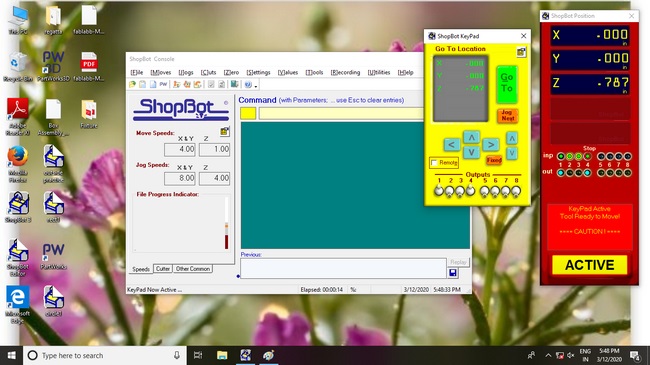
- Click on the Shopbot keypad to set the origin X,Y,Z as per requirement.
- used the keypad ,move the spindle over material and set the origin as zero.
- Now load the file, machine is ready to cut the part file,make sure that everything is fine.Turn on the machine with on switch.Turn on the spindle and vacuum.
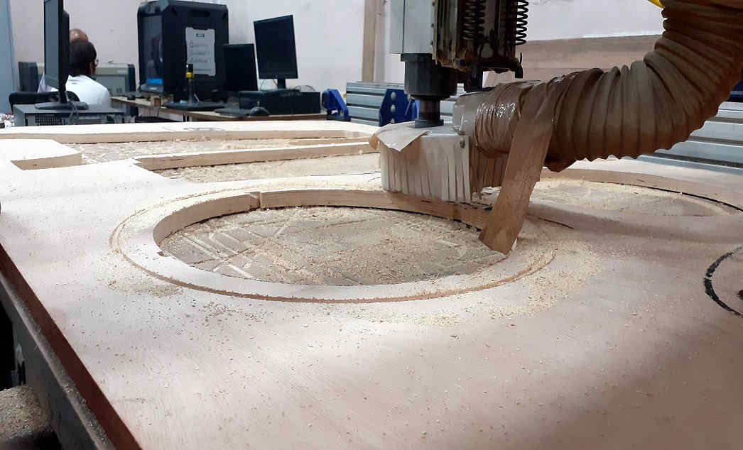
- Set the plywood on the scrificial layer(machine bed).
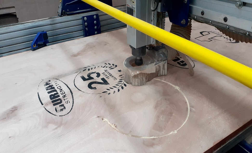
- Machine start cutting the plywood a/c to inner tool path.
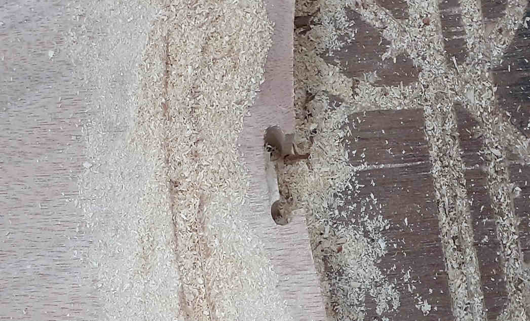
- Dog bone fillet cut by machine.
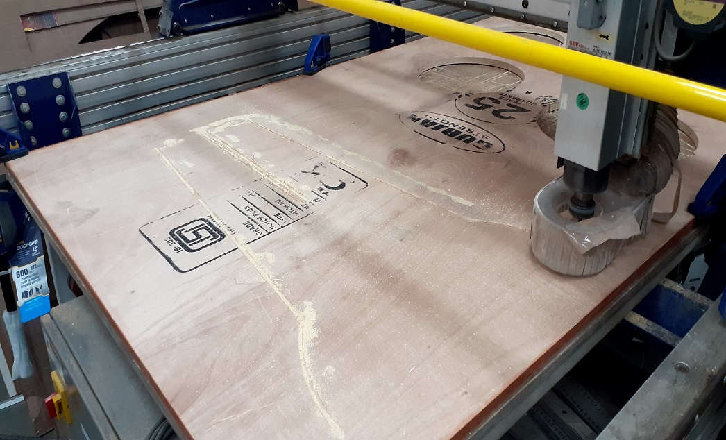
- Machine cutting the plywood a/c to the outer tool path.
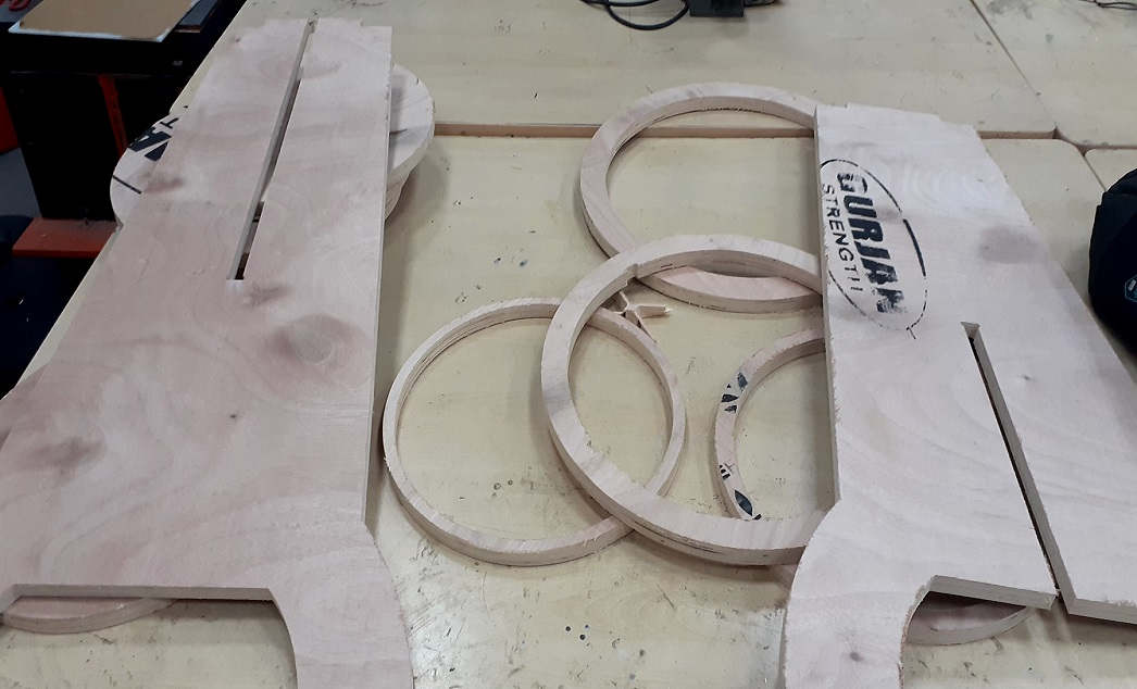
- The final object parts are ready.
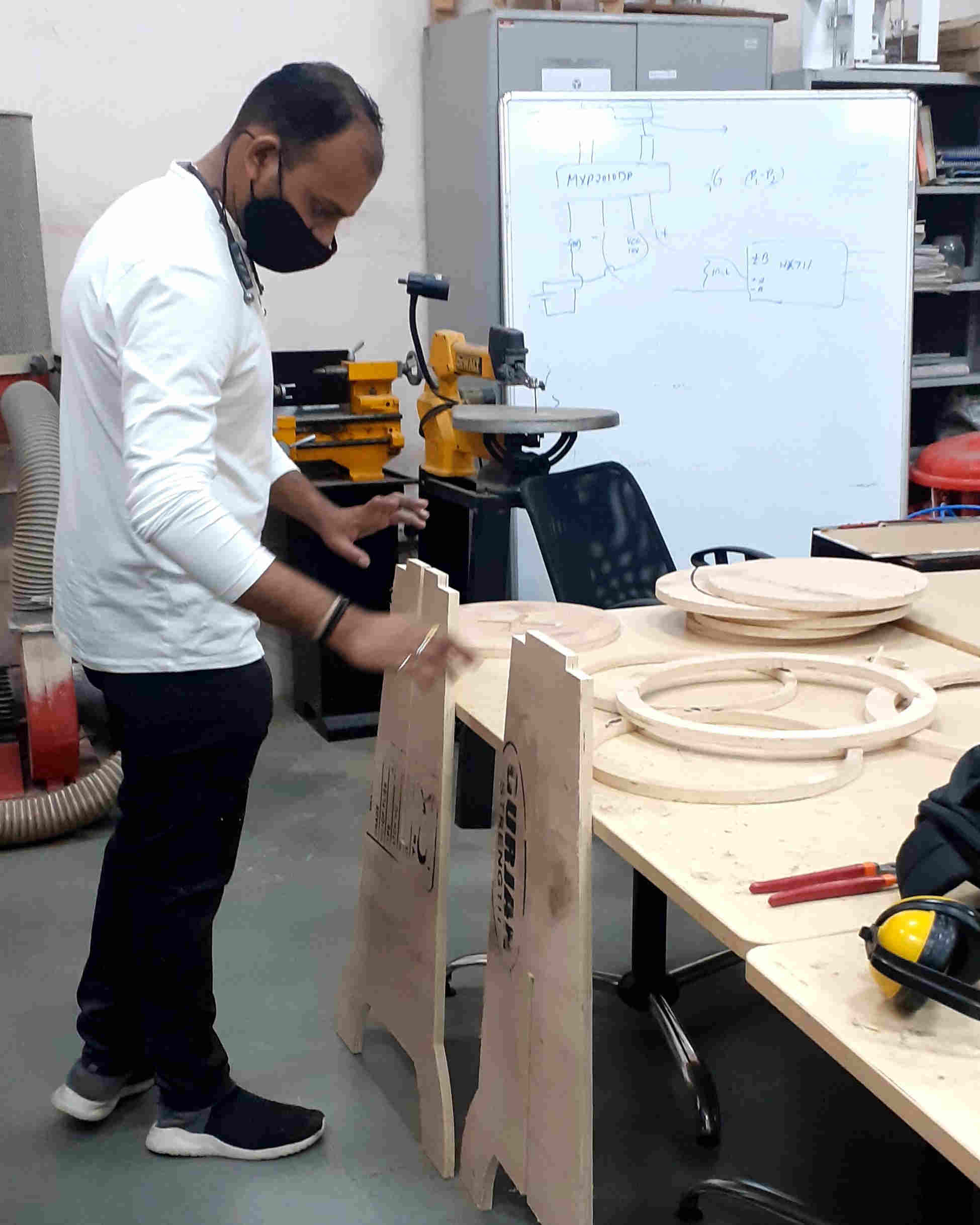
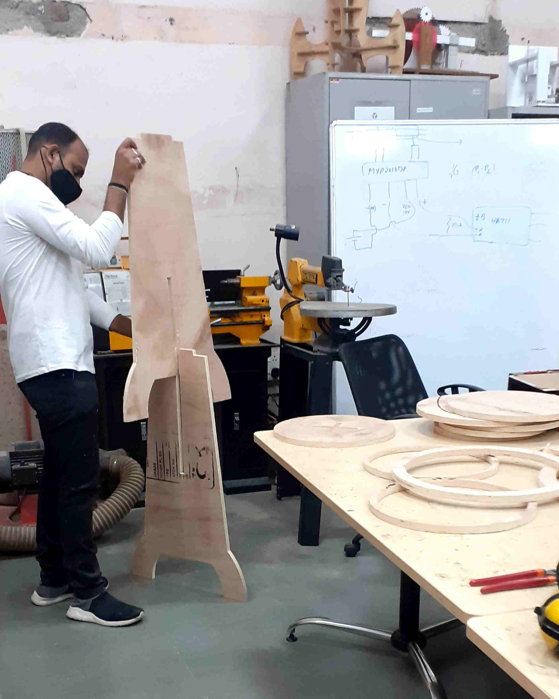
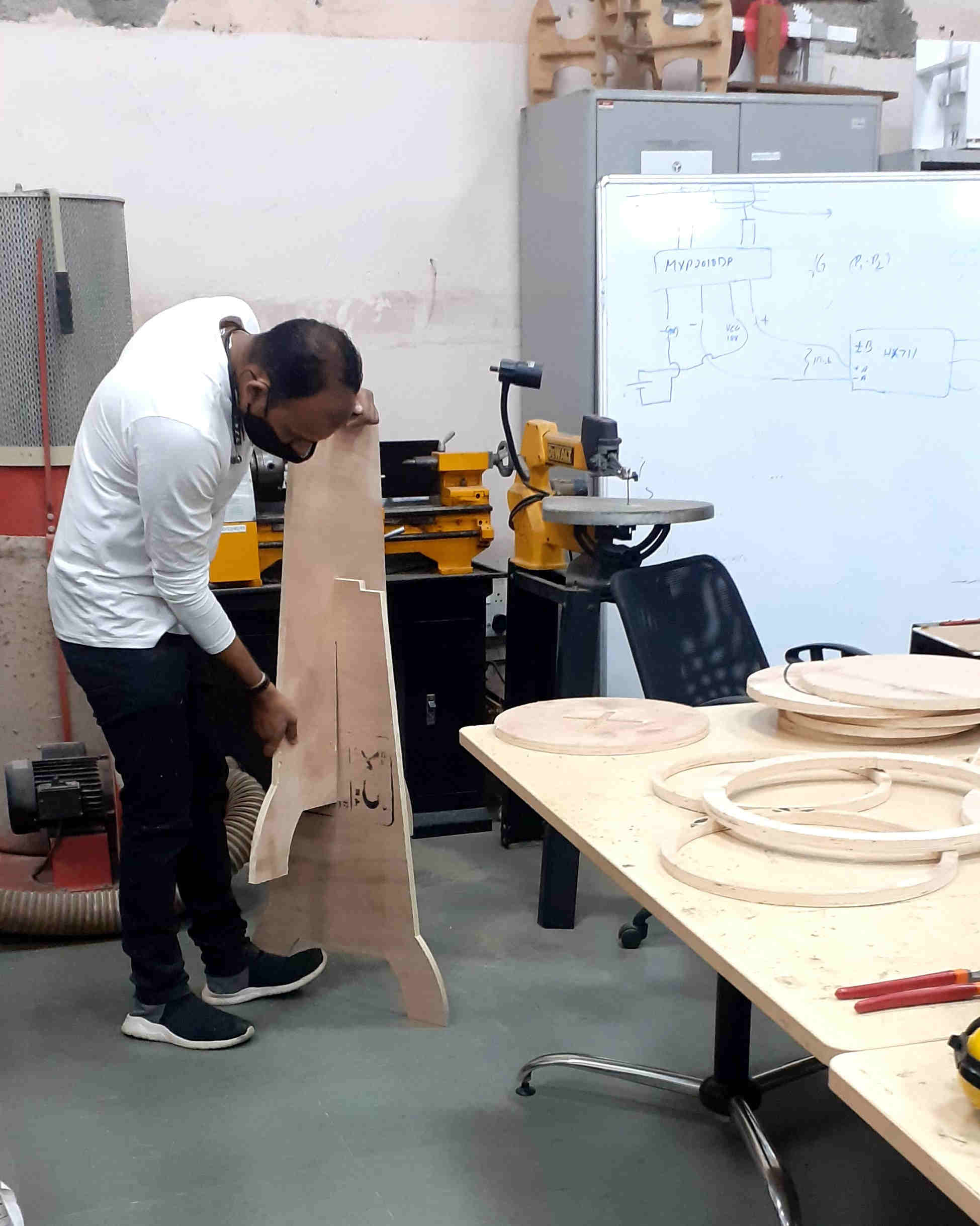
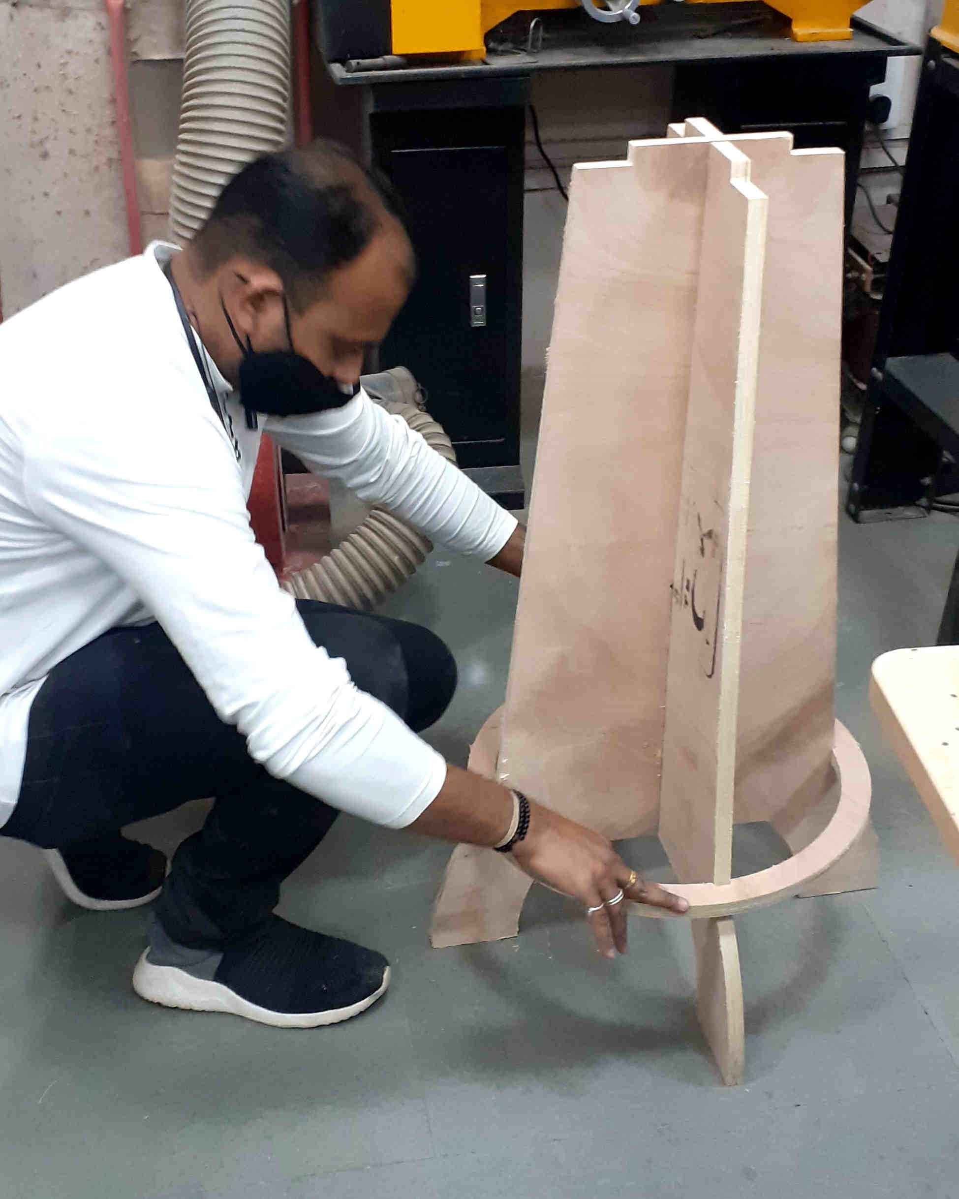
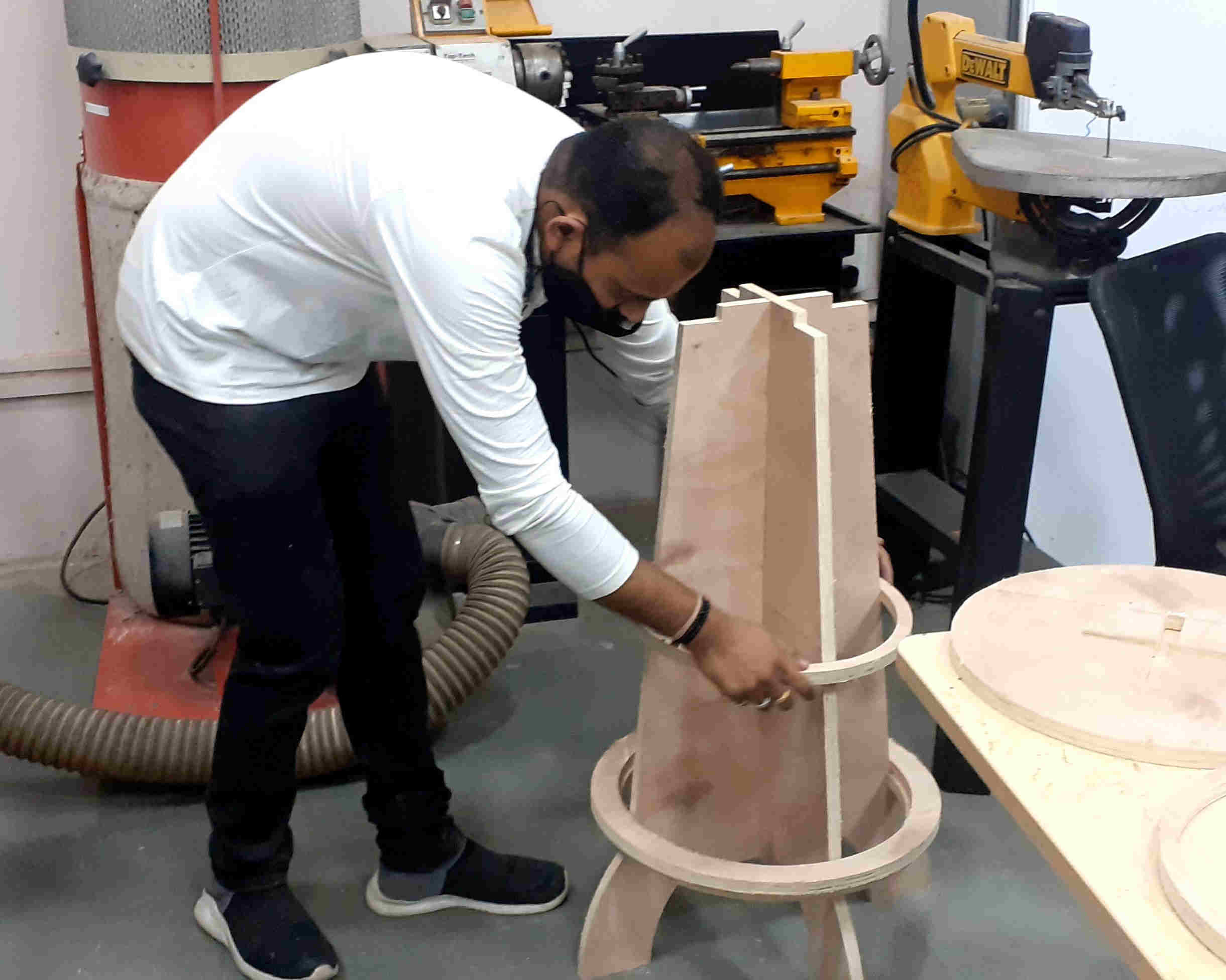
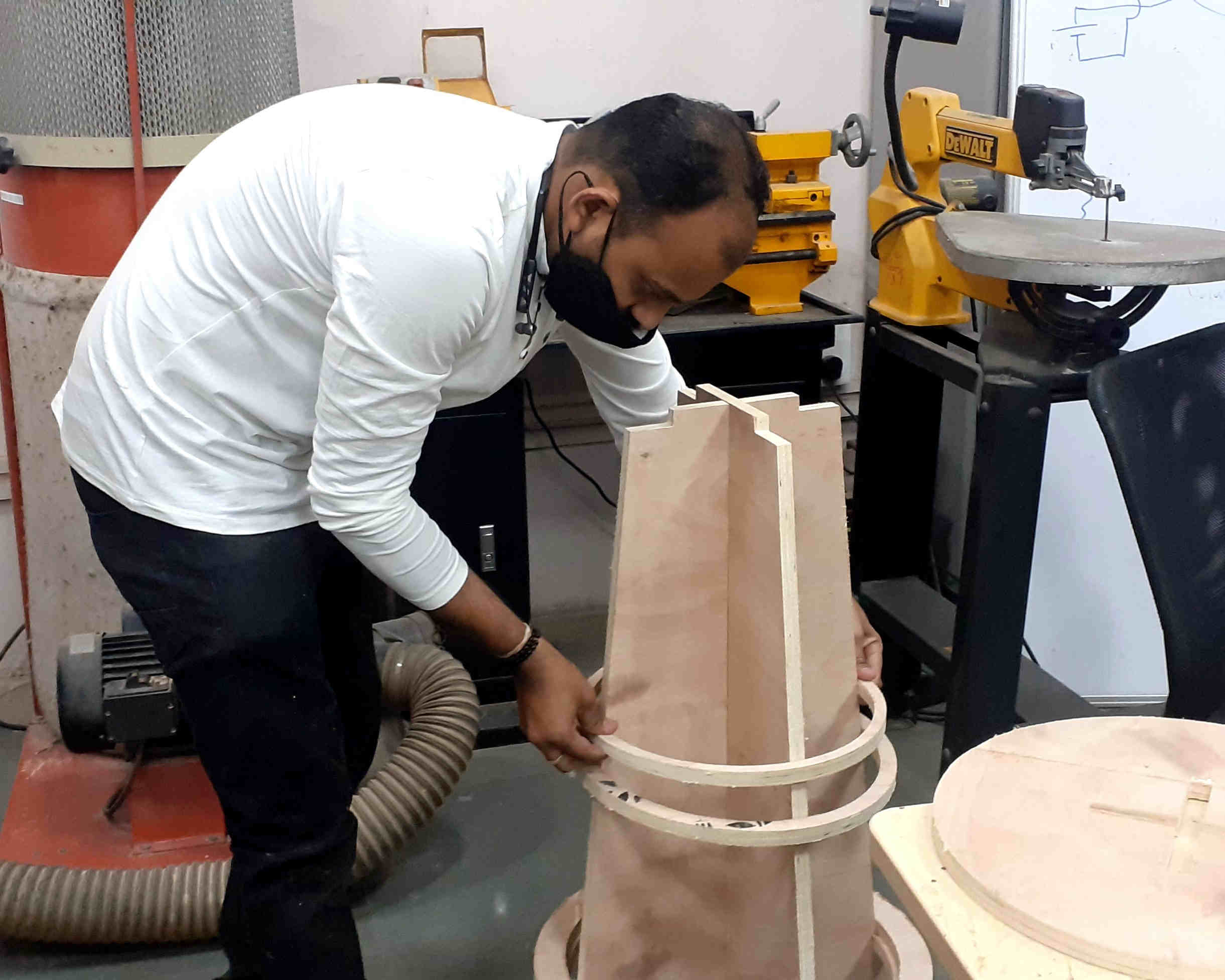
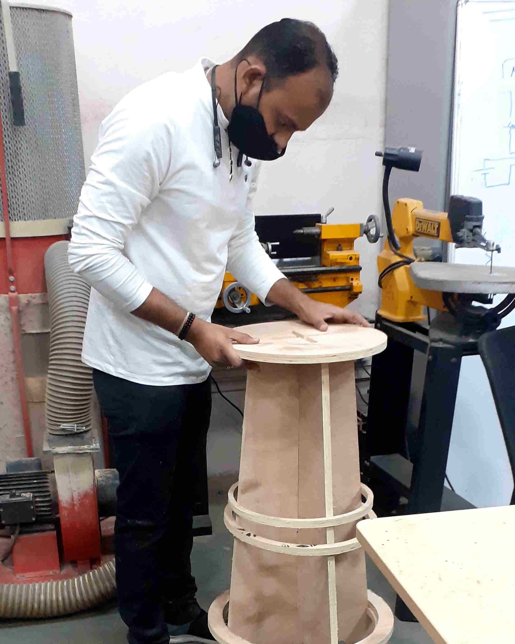
Assembling Parts
Now its time to assemble all parts of design object.
Learning outcomes
- Used the Rhino. sowtware to design the object.
- Used the "Partworks" software for generating cutting tool path.
- Find the importance of "Dog bone" and "T bone" fillet while designing the pressfit assembly.
- Handle the "Shopbot" CNC cutting tool (machine) for cutting wooden material.
Downloads
SAMS-Smart Azolla Multiplier System by Anand S. Tale is licensed under CC BY-SA 4.0![]()
![]()
![]()