Equipment Details
Belty V2.0 is a belt driven 3D printer designed and built in EnergyLab-Lome. This is the result of our second spiral, which built on our first spiral named Belty. You can find details on how Belty was made here. In the first version we were focused on the belt system and optimising it using the available materials we could lay our hands on. With this Version 2, we focused more on making an actual 3D belt printer where we added an extruder and a new RAMPS control board using the Merlin firmware. Belry V2.0’s specifications are included below.
Specifications
| Custom DIY Urumbu based Wire-cutter | |
|---|---|
| Materials | 2020 extruded aluminum, laser cut plexi-glass, PLA printed parts |
| Table Size | 250 x 250 mm |
| Work Plan | 250 x 250 x 300 mm |
| Number of Axes | Three : X,Y & Z axis |
| Maximum Empty Travel Speed | 4800 mm/min |
| Working Speed | 4800 mm/min |
| Operation type | the X-axis uses the beehive system,the Y-axis uses a conveyor belt sytem powered by a stepper motor and the Z-axis uses the screw rod mechanism |
| Motors | Nema 11 (x and z), Nema 17 (y) |
| Power Supply | 12V system with AC220V, 50HZ converted computer power supply |
| Run Command | G Code |
| Operating System | Merlin Firmware |
| Support Software | Black Belt 3D/Raise 3D |
How It’s Made
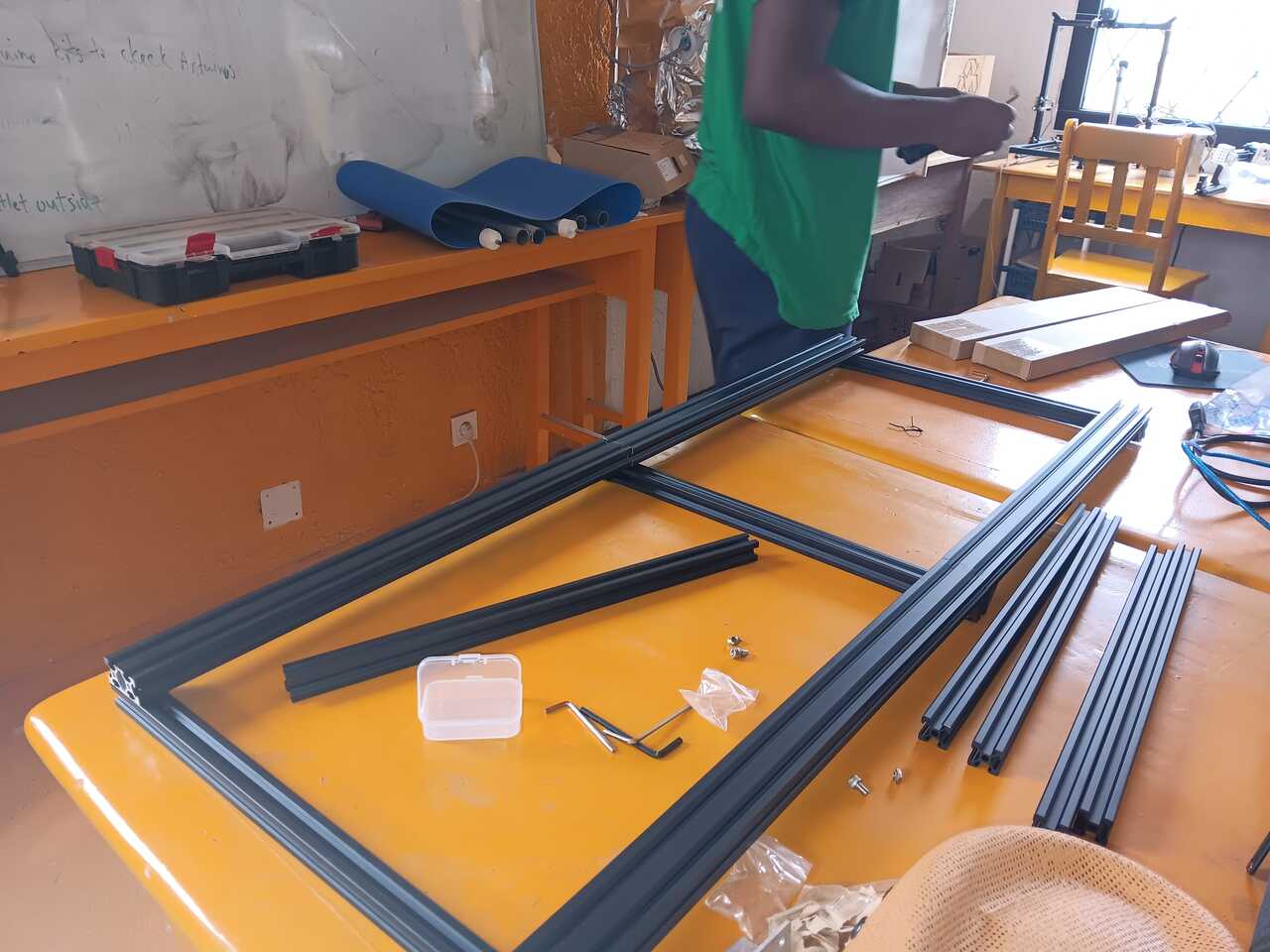
The following section will walk through how builty was designed and built. The first step was putting together the frame.
Construction of frame
We used extruded aluminum, both double and single slot. The double slot base was two 500 mm pieces placed end on end.
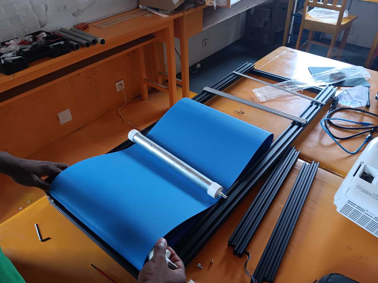
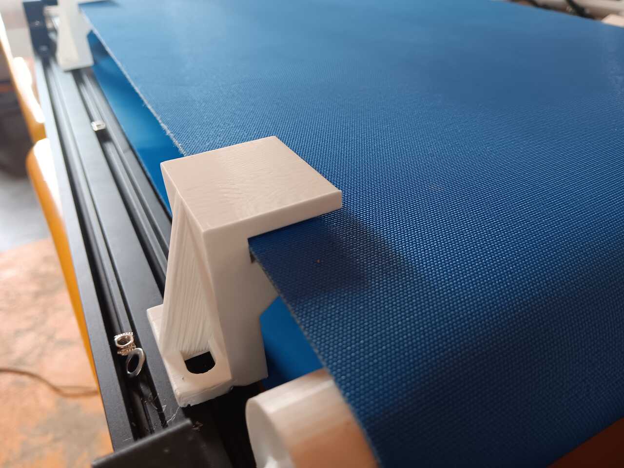
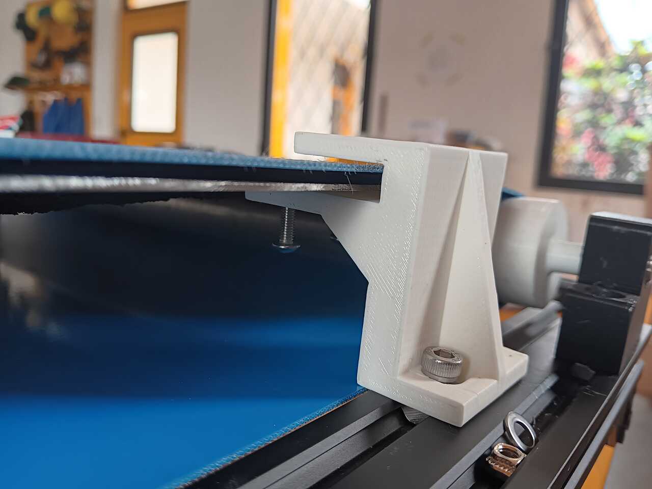
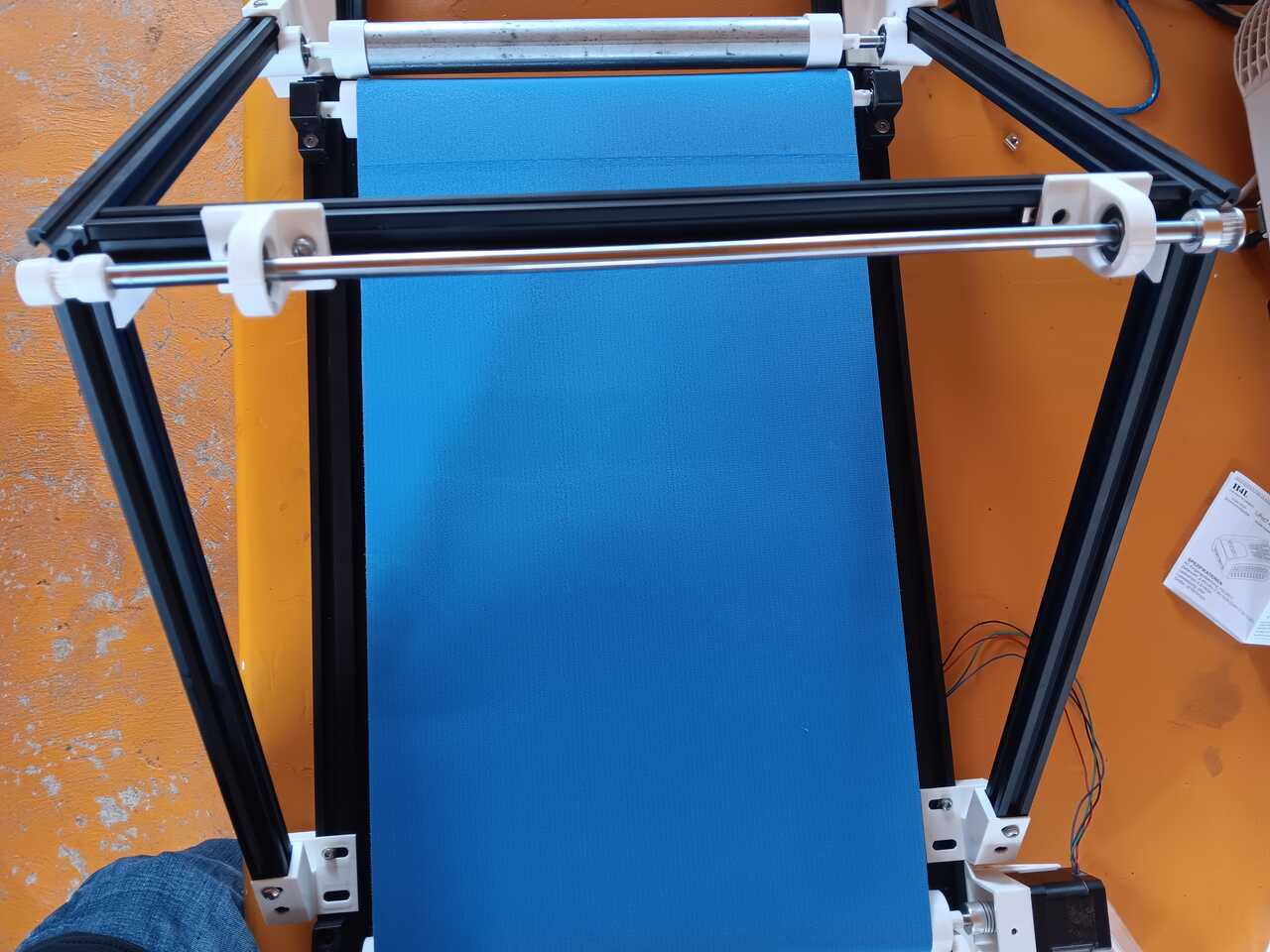
Installing the belt
Next we installed the belt.
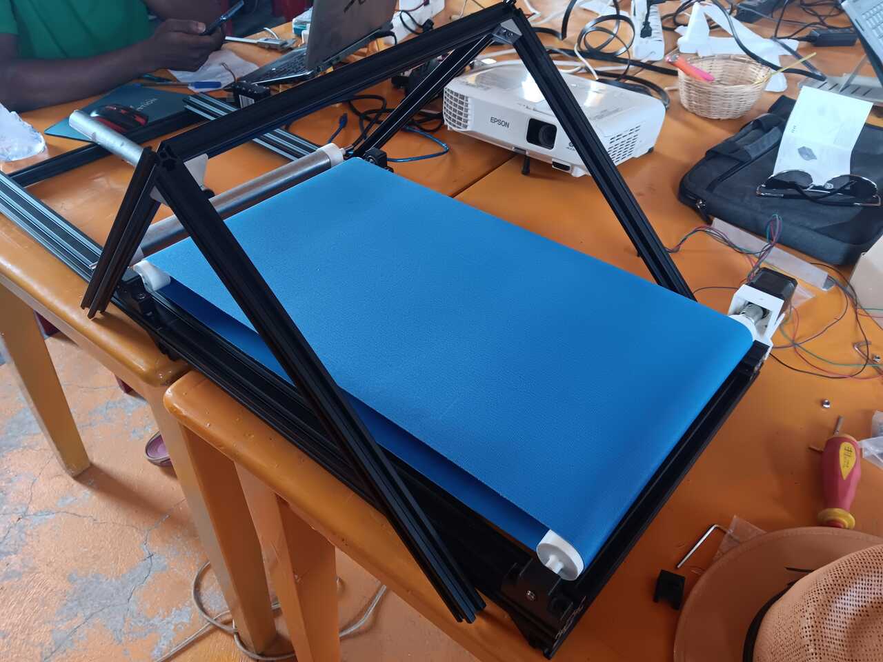
We then designed and 3D printed parts to hold the top carriage . Design images and files to come.
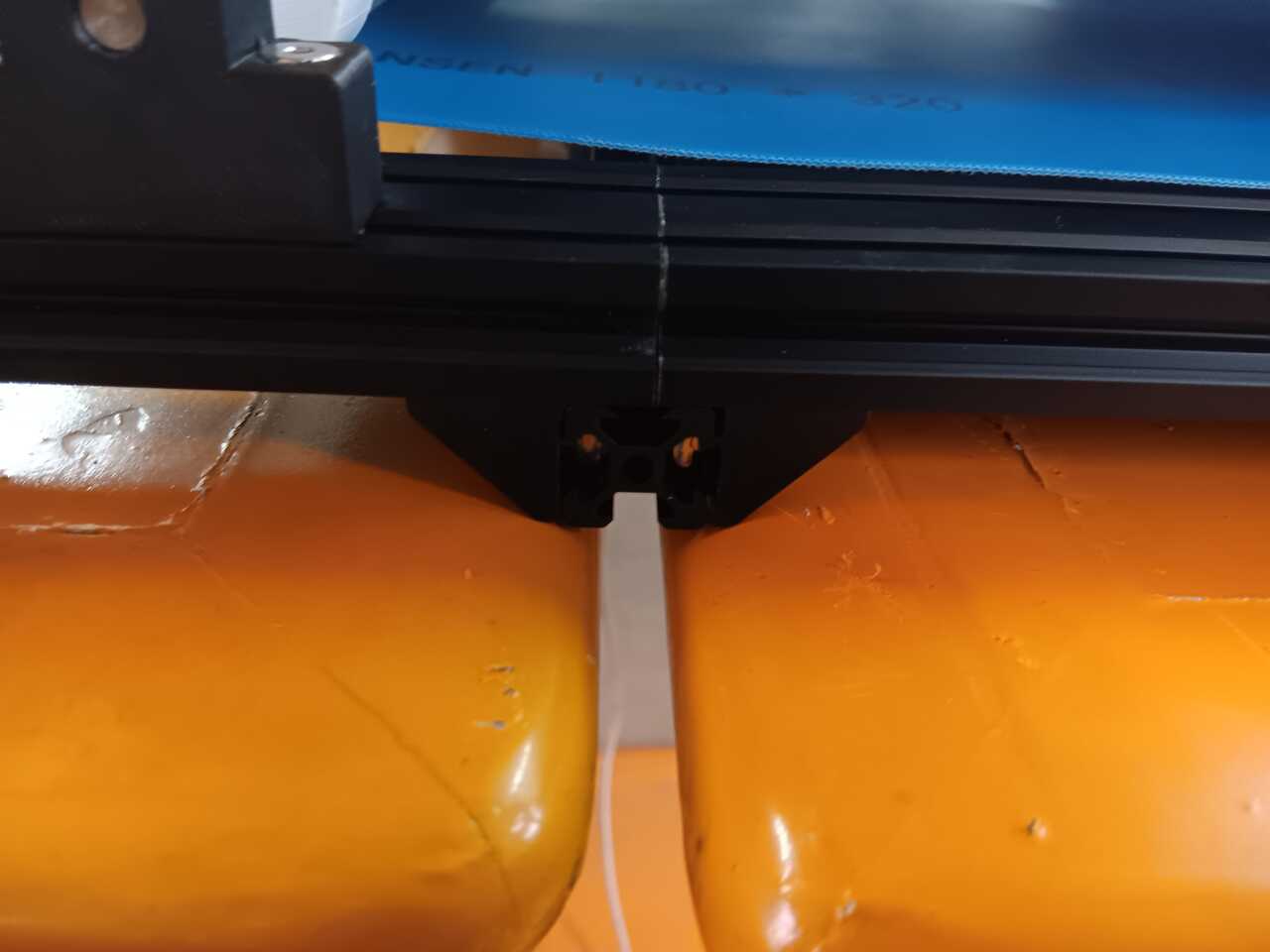
Drilling and tapping
With the design, we found it could be difficult to keep the t-nut in place to screw the attachments into, specifically where the 45 degree is because the t-nuts would slide down into the printed part.
To resolve this we came up with two methods:
(1) Using a magnetised allen key down the slot to hold the t-nut in place, or
(2) Drilling and tapping directly into the aluminum
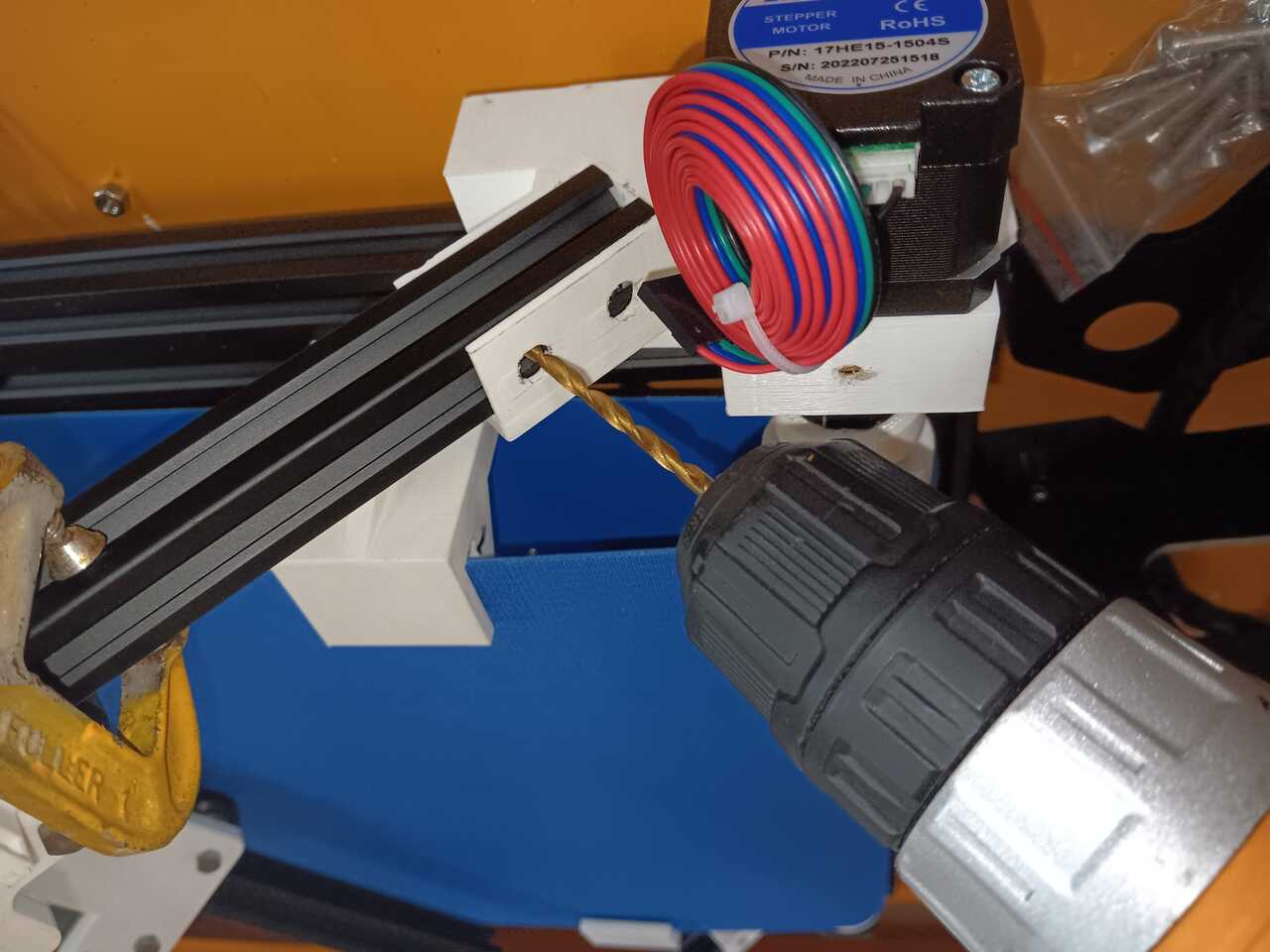
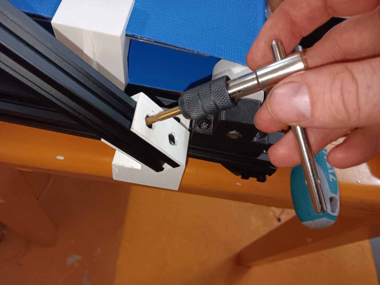
Feel free to use whichever method works best for you. We opted for drilling and tapping to save on t-nuts and for extra regidity.
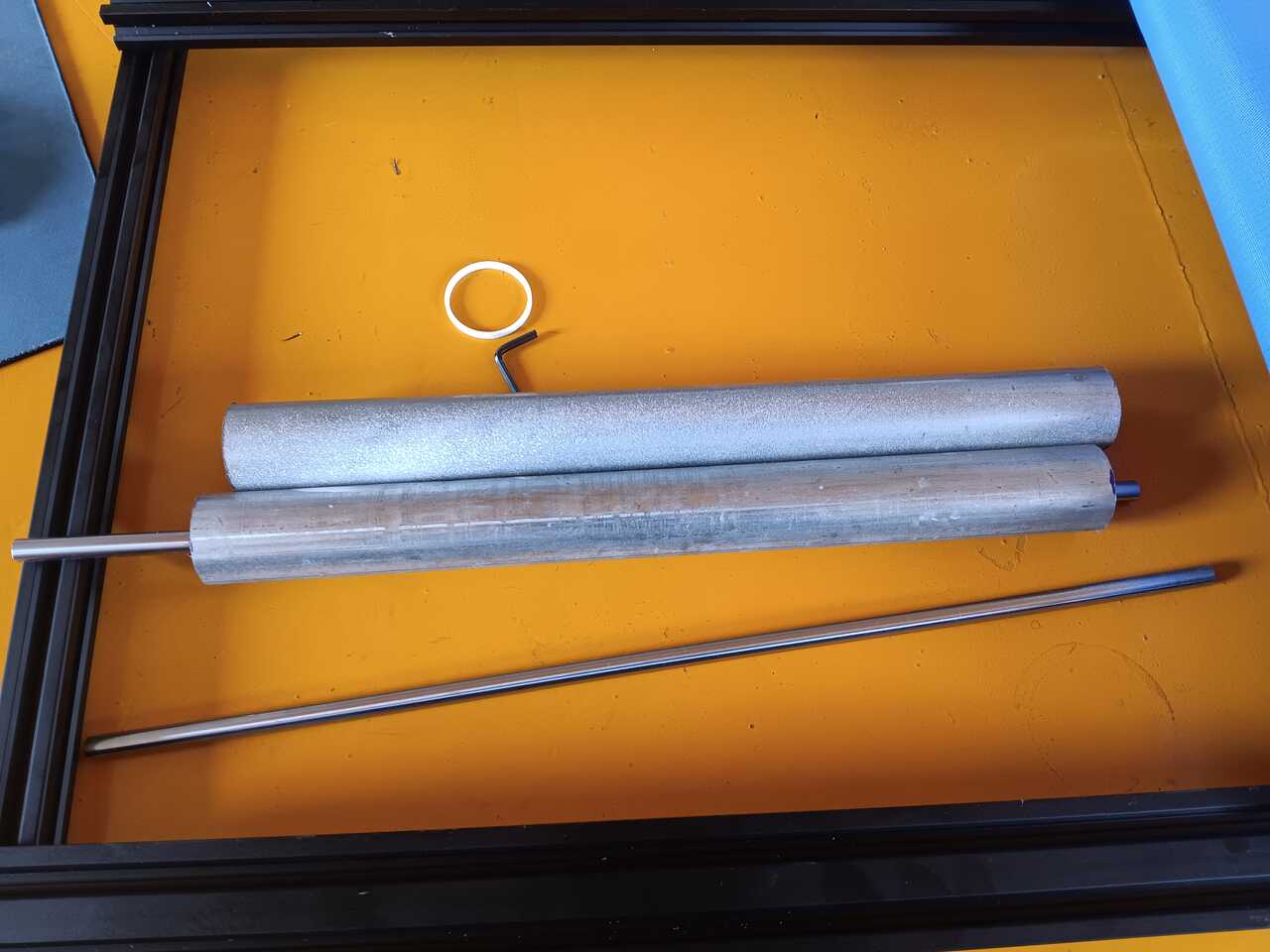
Rollers design
We cut rollers out of 1" galvanized steel tube. We printed end caps and also used a linear axis down the center to ensure everything was centered.
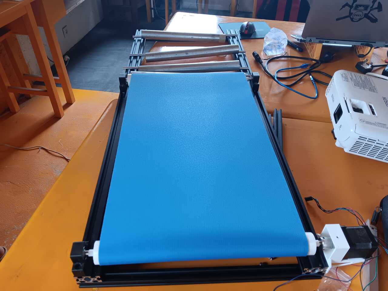
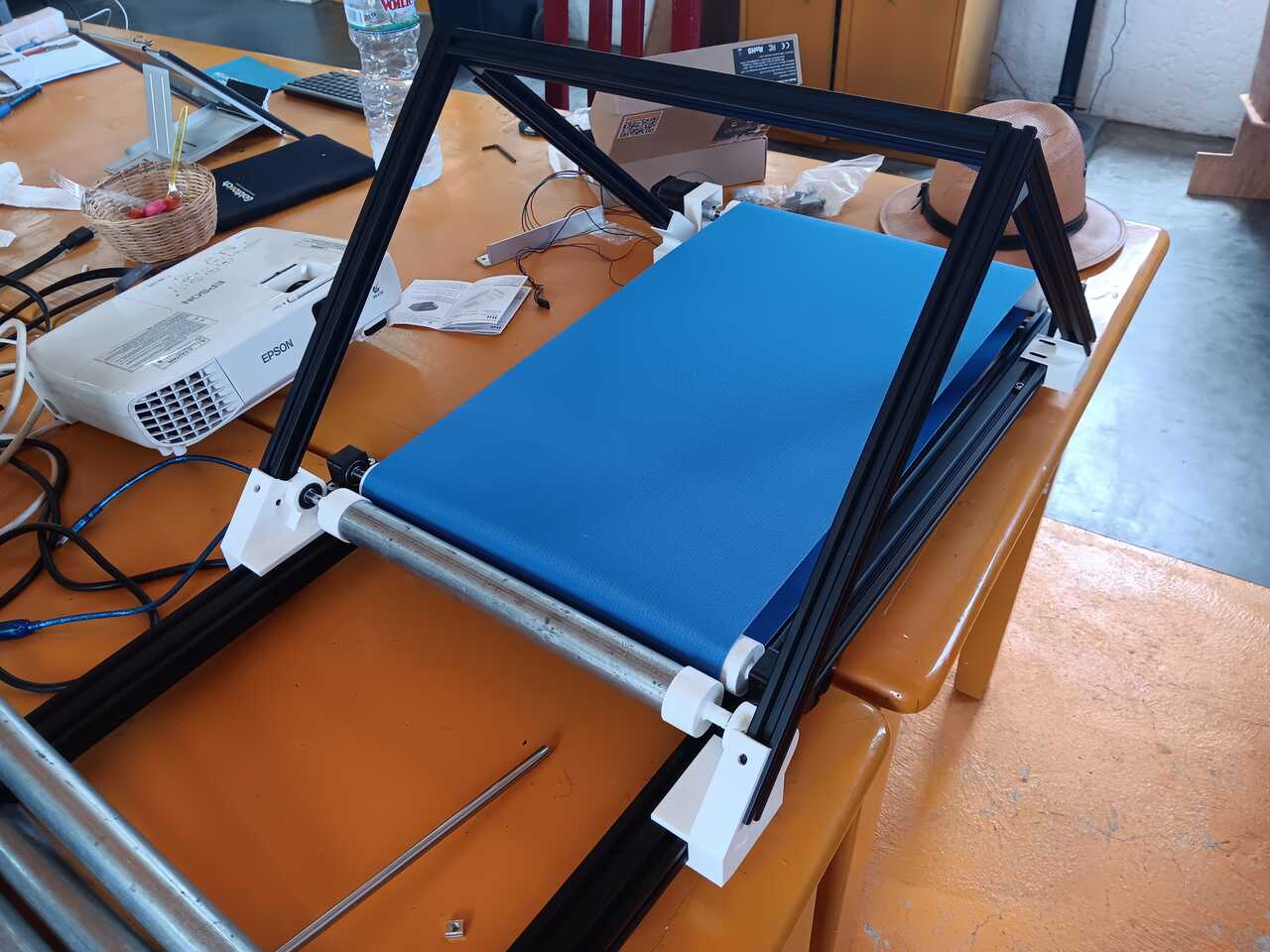
Final result
Here is a photo of the final result.
Construction of the heated bed
The next part of the design included design of the heated bed.
Version 1
We originally started with a double heated bed with one long piece of steel plate connected.
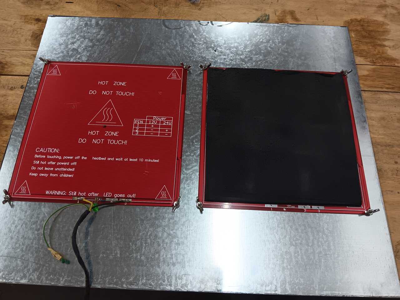
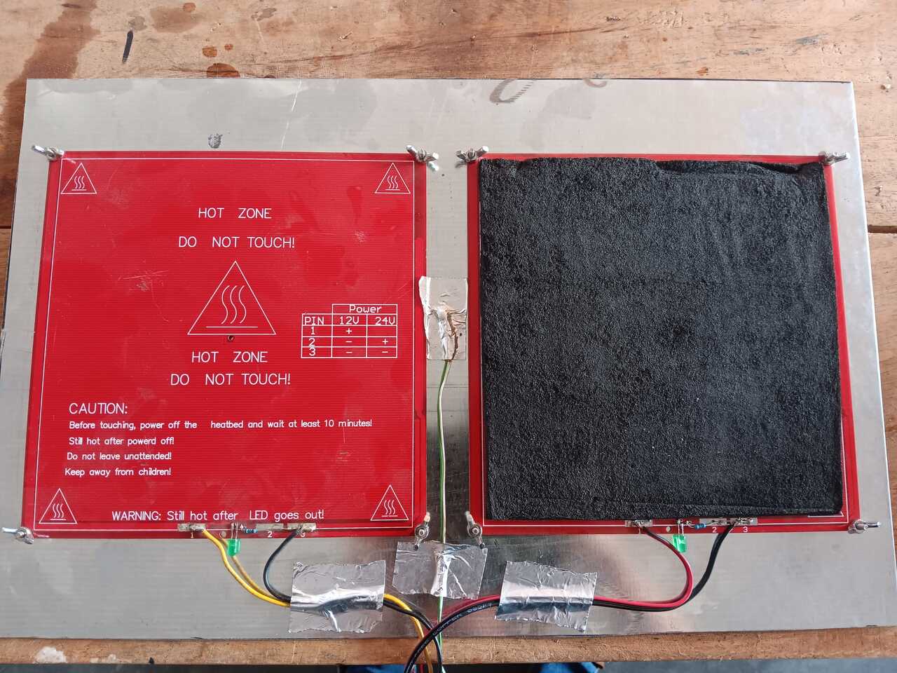
We also designed and printed clips to hold the bed in place and keep the belt touching the bed.
This version had too much power draw, and resulted in too much friction on the belt for the rollers to turn effectively. So we moved on to version 2.
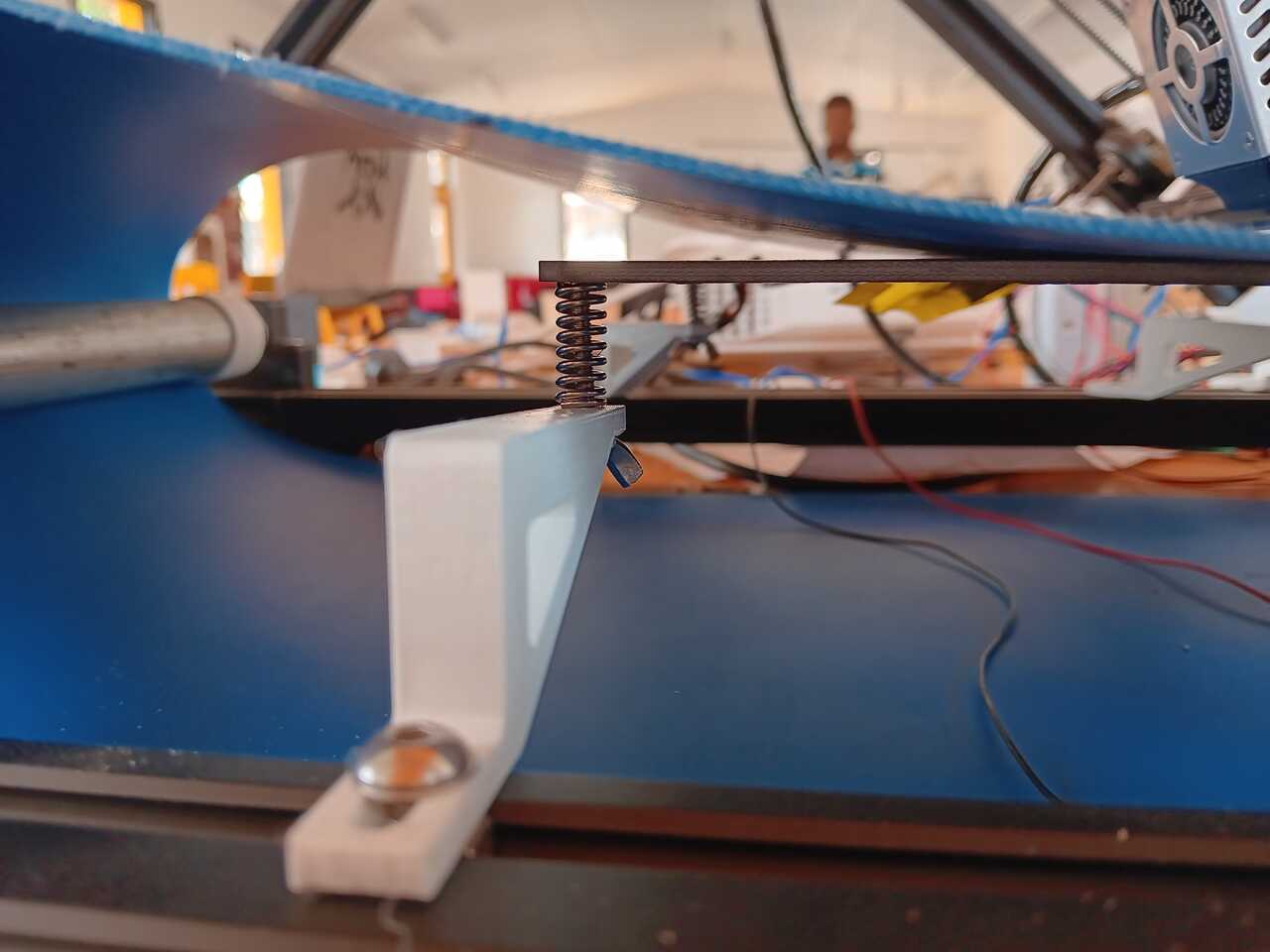
Version 2
For version 2, we opted for a single heated bed with spring loaded bed levelling. This resolved both the power draw issue and the belt friction issue.
Design and contruction of the mechanisms
Once the frame was in place we next had to design the mechanisms to move and control the 2 linear axes (X + Y) and the one rotational axis (Z). To orient you:
(X) The X-axis is the axis that moves across the belt and holds the extruder,
(Y) The Y-axis is the axis that moves up and down the 45 degree frame,
(Z) The Z-axis is the belt.
In the following sections we will provide details about how each of the axes’ mechanisms were designed.
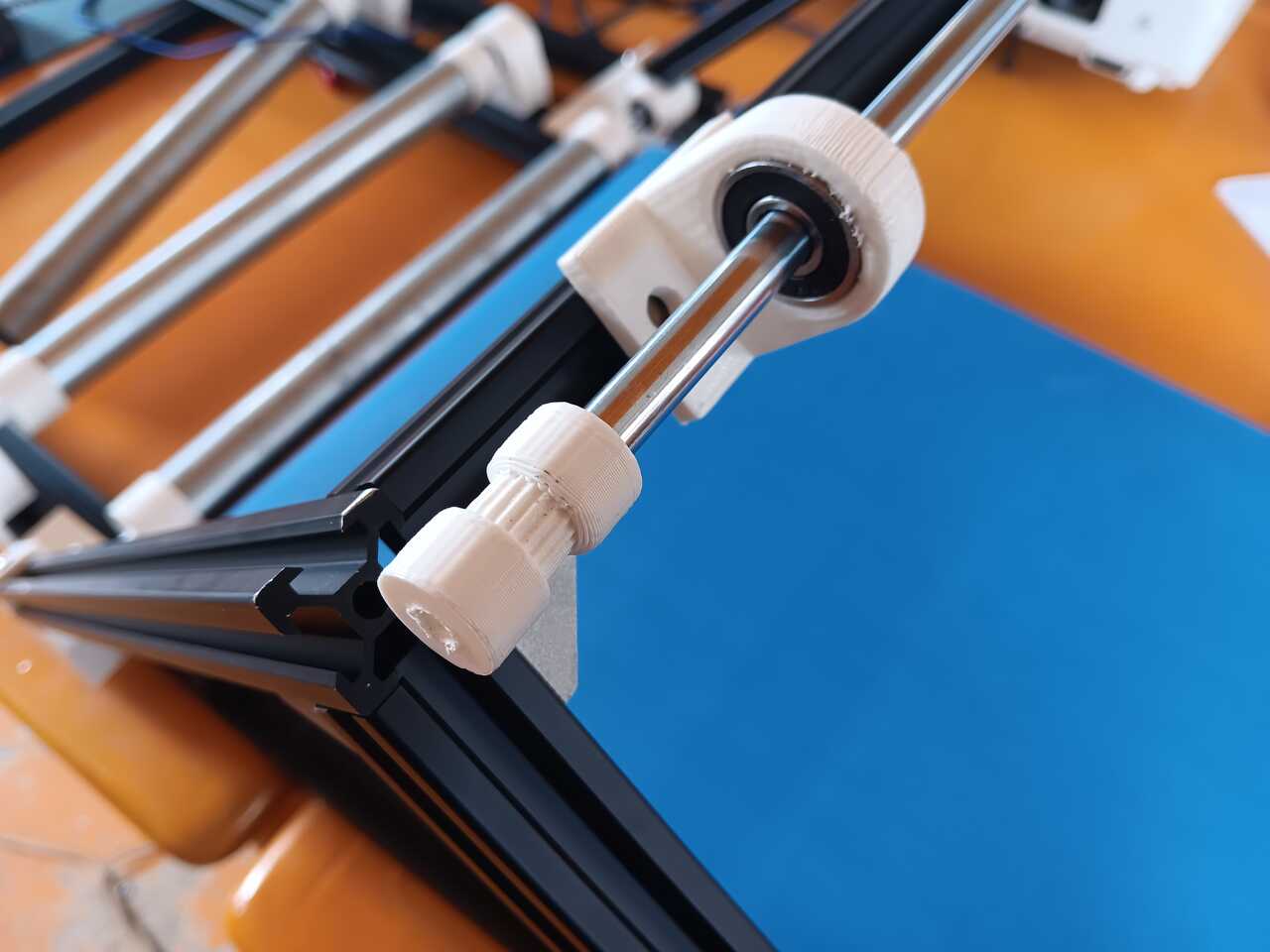
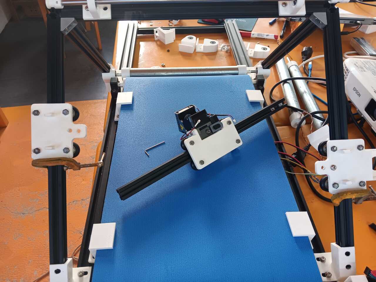
X-axis: Belt Drive - Single Pulley
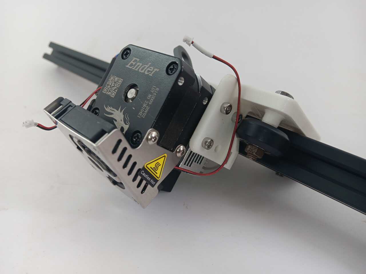
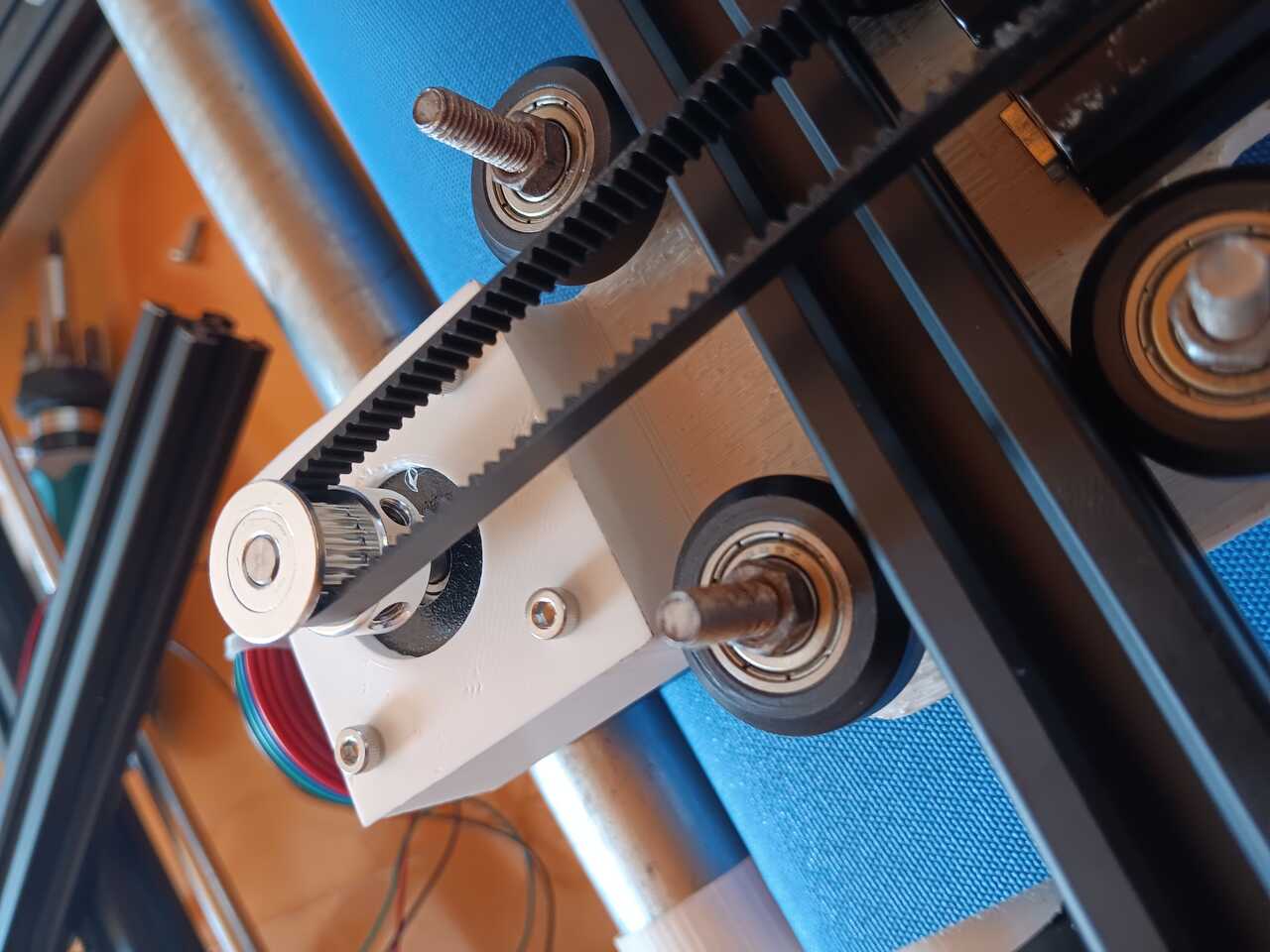
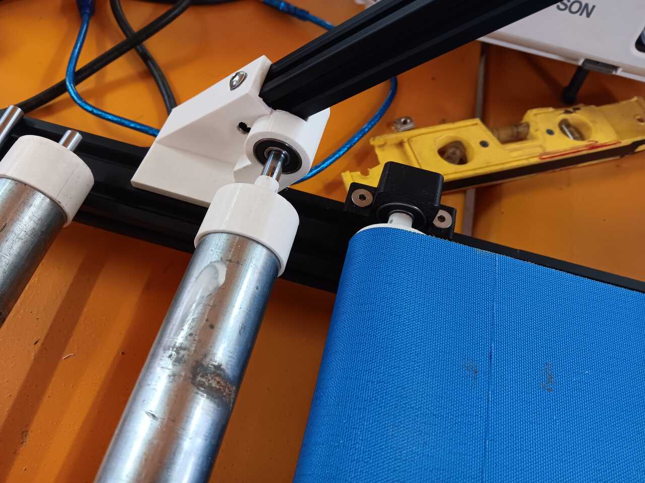
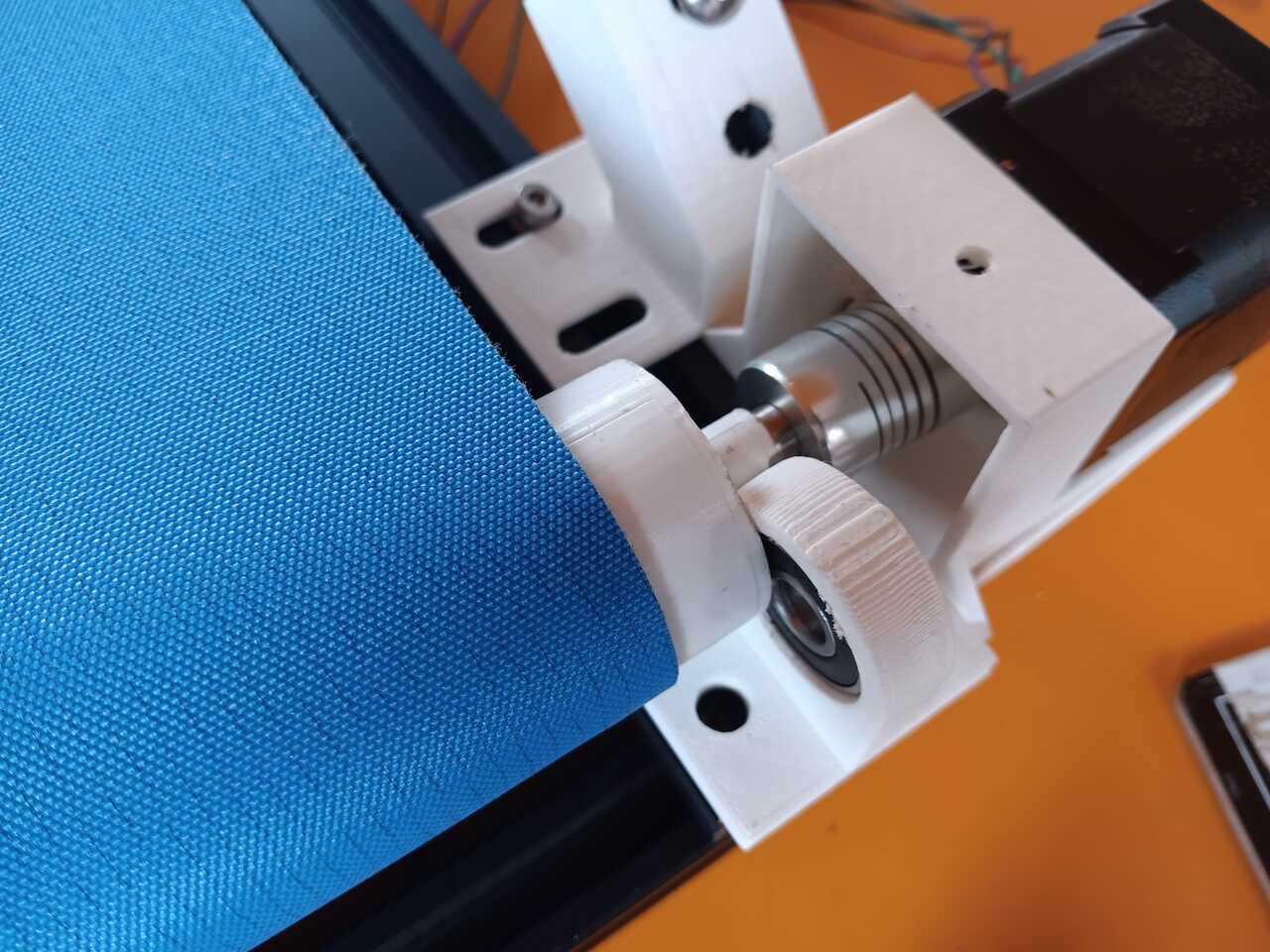
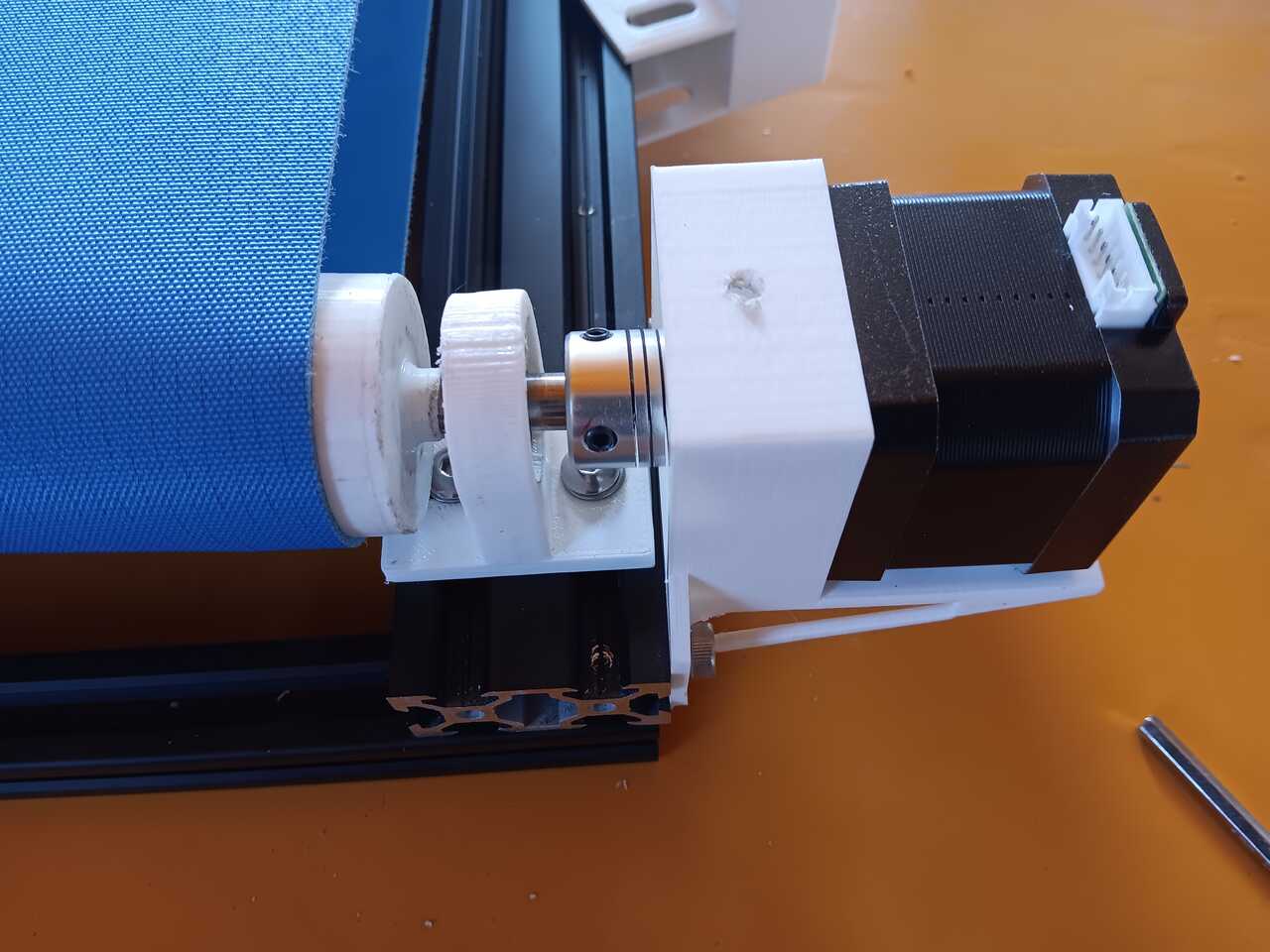
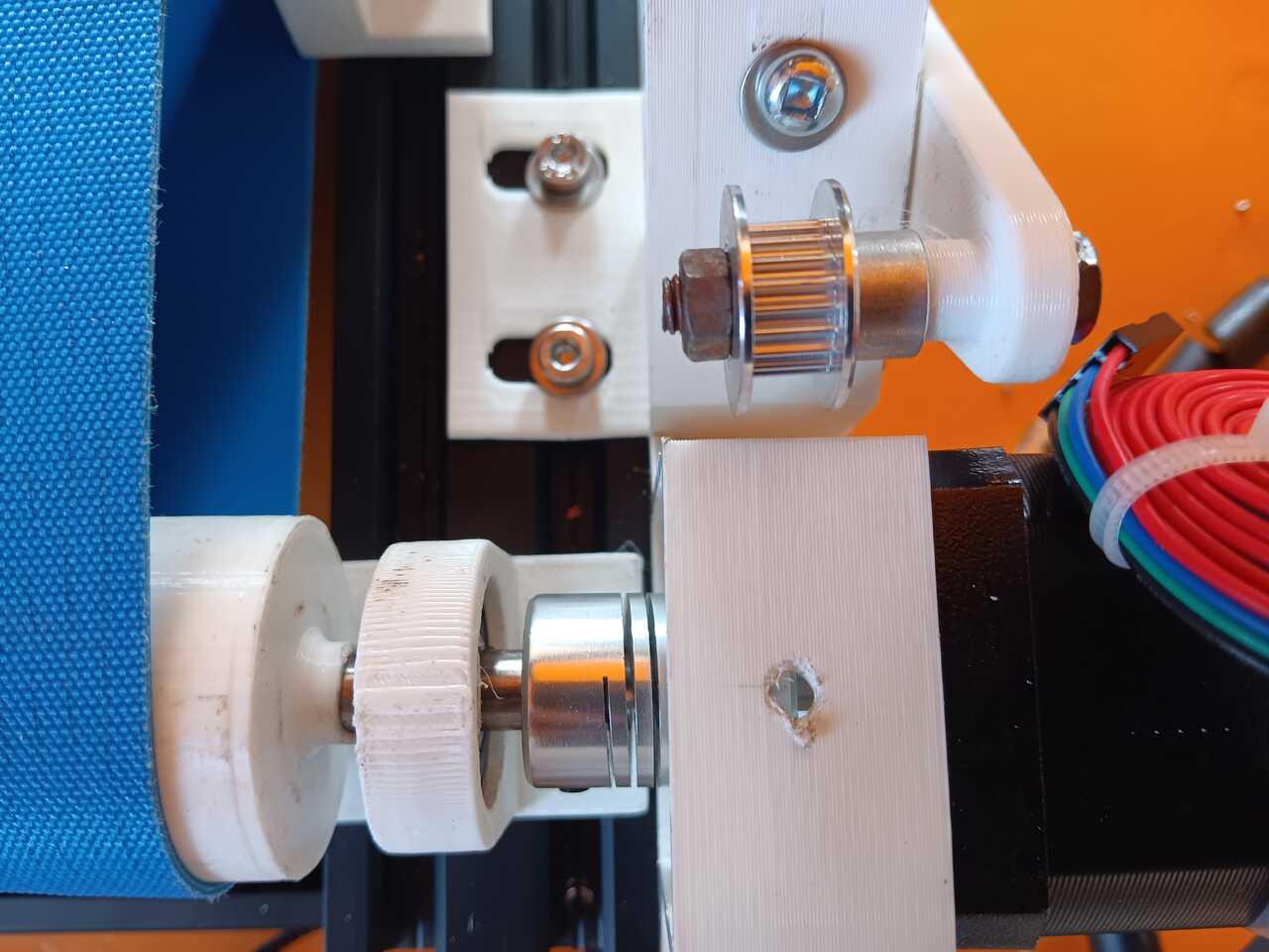
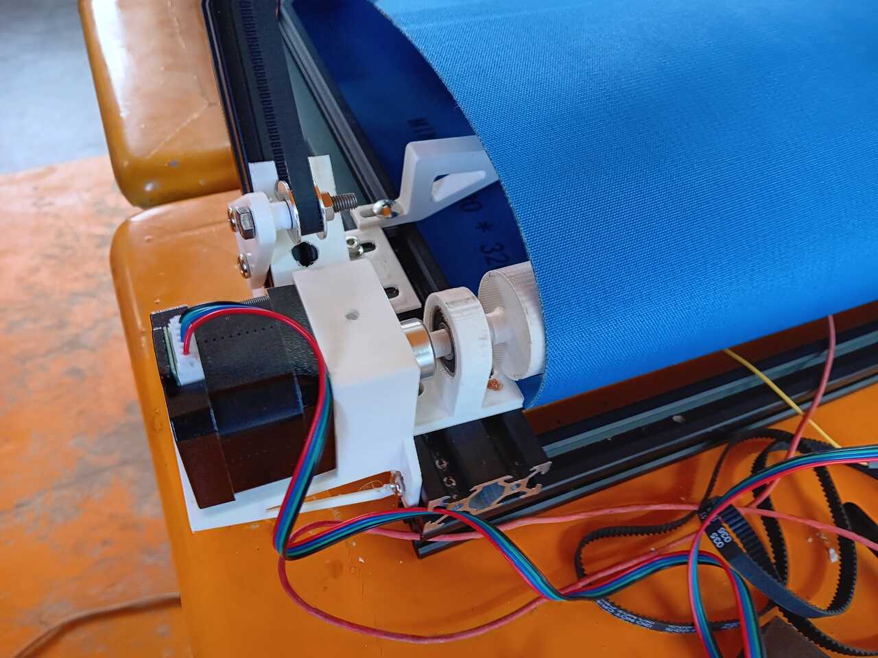
Y-axis: Belt Drive - Dual Pulley
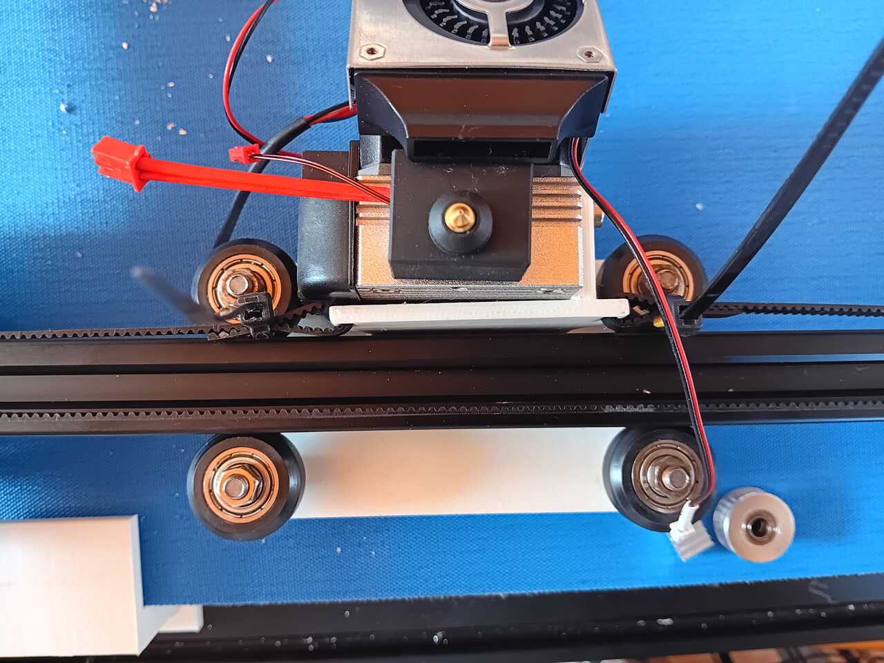
For the Y-axis, one challenge was that the RAMPS board (more details below) only has one stepper driver for the y-axis as most 3D-printers only have one motor to move the bed. This is a challenge because the carriage has two sides. To overcome this, we used a linear axis supported by two bearing to transfer the motor power along the shaft to both belts on both the near side, and the far side. Below are photos of the y-axis shaft that runs both pulleys.
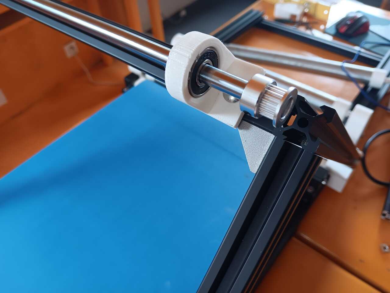
Below is an image of the belt carriage at the bottom of each y-axis.
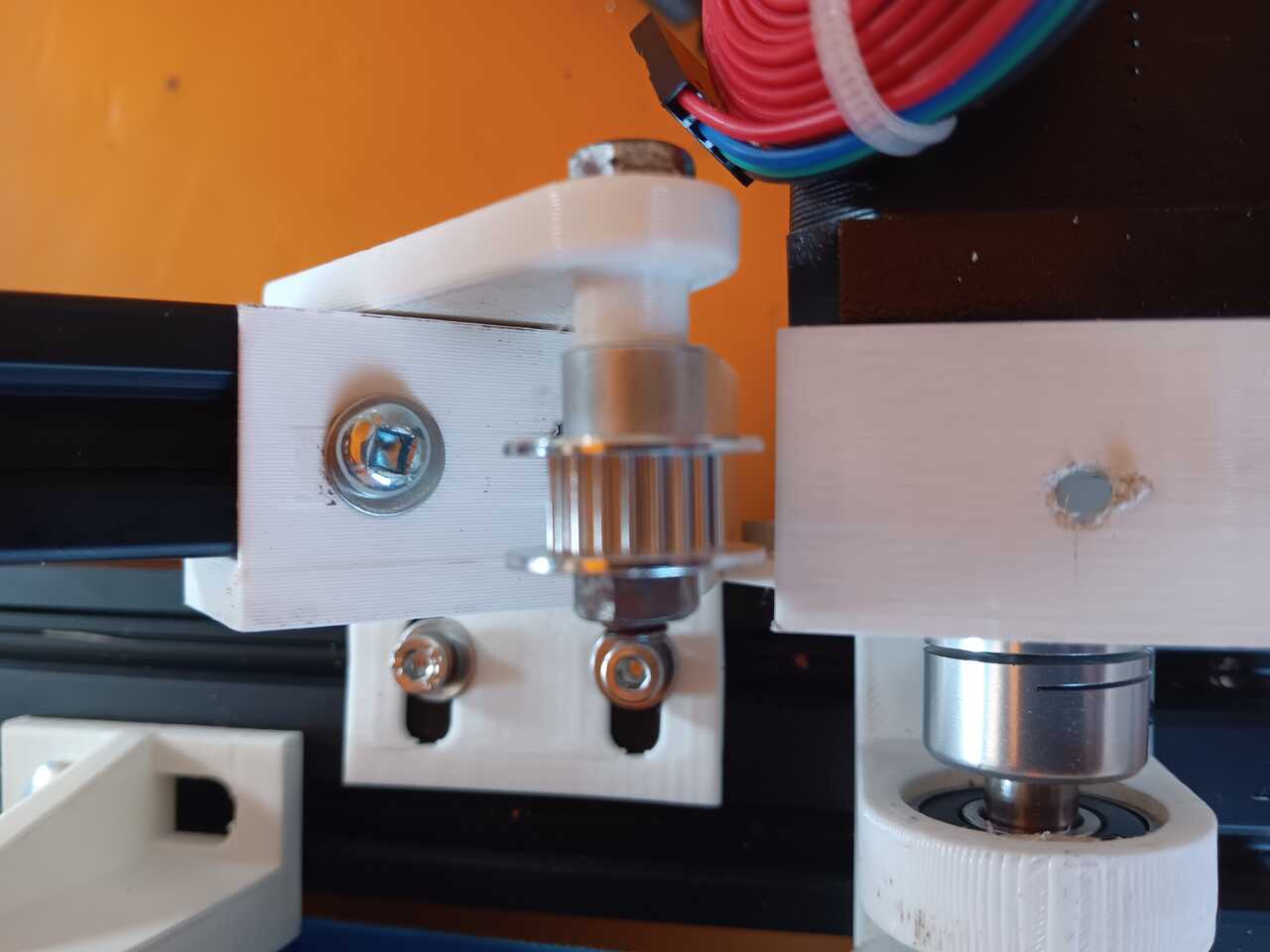
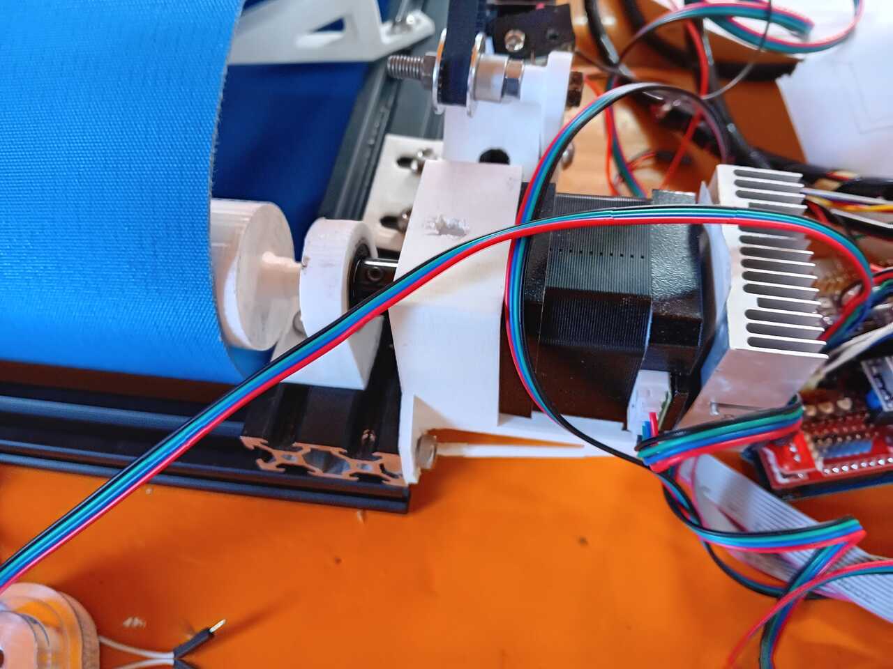
Z-axis: Direct Drive - Dual Motor
The z-axis is a simple direct drive.
Version 1
Version 1 of the z-axis used only one motor, but we found that we had troubles with the belt.
To resolve this, we had two options:
(1) the first was to add a gear mechanism, but the was a challenge because we didn’t have much room.
(2) the second was to add a second motor as the RAMPS board is already designed to have two z-axis motors. We opted for this option, as it required the minimal amount of redesign. For future versions, we will explore using a gearing system to reduce BOM cost.
Version 2
As mentioned above, we opted to go with adding a second motor as it was the simplest fix that required the minimal amount of redesign. Belty V2.1 may fix this design flaw. Below is a photo of the two z-axis motors.
Once we added the second motor, we resolved our z-axis issues of losing steps or the belt not moving the correct distance. Below is a result of the z-axis test.
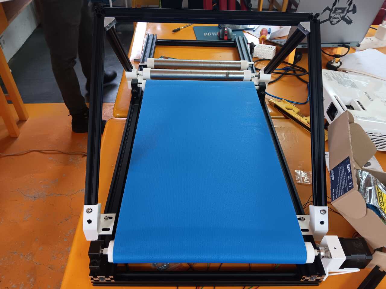
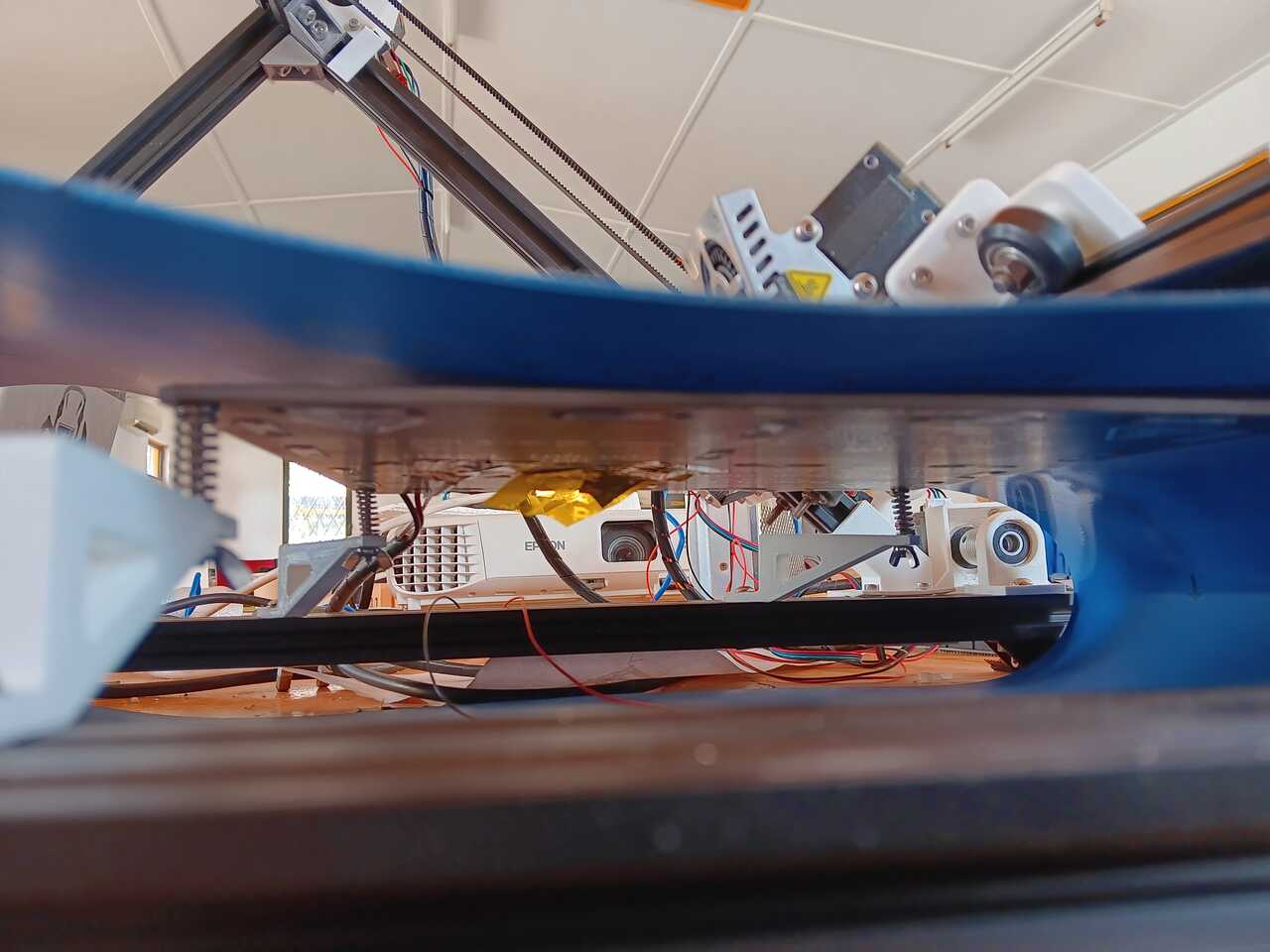
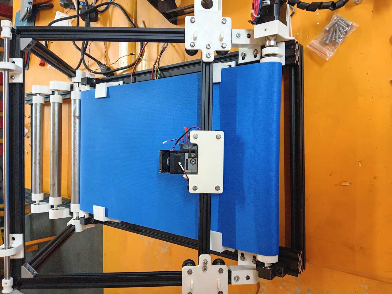
Final Mechanical Assembly
Once all of the axes and their mechanisms were designed, we then assembled all ll the components together. Below is a photo of the final mechanical assembly showing all of the axis mechanism before installation of all of the belt-drives.
Electronics
Once the frame was constructed and the mechanisms were built, we moved on to the electronics. We used the RAMPS 1.4 RepRap Arduino Mega sheild (link) as the motherboard for our system.
Ramps 1.4 board info: https://reprap.org/wiki/RAMPS_1.4
Firmware
Marlin firmware info: https://www.my-home-fab.de/en/documentations/reprap-firmware/installing-marlin-firmware-on-ramps-1.4 https://marlinfw.org/docs/configuration/configuration.html#-home-offset
Link to Arduino 1.5.4: Windows: https://downloads.arduino.cc/arduino-1.5.4-r2-windows.exe Other versions: https://www.arduino.cc/en/software/OldSoftwareReleases#previous
Firmware installation guide: https://osoyoo.com/2016/06/29/ramp1-4-board-for-reprap-3d-printer-firmware-installation-guide/
u8glib library: https://osoyoo.com/driver/U8glib.zip https://github.com/olikraus/U8glib_Arduino https://github.com/MarlinFirmware/U8glib-HAL
Marlin firmware: https://osoyoo.com/driver/Marlin-ramps12864.rar
Marlin V2.1.1: https://github.com/MarlinFirmware/Marlin/archive/2.1.2.1.zip
Example config files: https://github.com/MarlinFirmware/Configurations/tree/release-2.0.9.6 Configurations/config/examples/Creality/Ender-3/CrealityV422/
Configuration_adv.h Line 1536 -> uncomment: #define GCODE_REPEAT_MARKERS
Configuration.h
Line 92 -> BOARD_RAMPS_14_EFB Line 116 -> Baud rate 115200 Line 140 -> Name “Belty V2.0” Line 549 -> Define bed thermistor as type 1 Line 1180 -> #define DEFAULT_AXIS_STEPS_PER_UNIT { 80, 80, 23, 500 } Line 1286 -> Comment out z probing Line 1686 -> Comment out z homing direction Line 1715 -> Z max = 99999 Line 1743 -> Commount out Z min endstop Line 1715 -> Commount out z max endstop Line 2458 -> Charset to JAPANESE Line 2473 -> Uncomment SD support Line 2744 -> Uncomment the LCD screen line
Calculation of 23 comes from the following:
Diameter of roll = 44 mm Diameter of shaft = 6 mm mm per degree = 2pi(Rroll-Rshaft)/360 = pi*(22-3)/360 = 0.1658 mm/deg
Nema 17 has 200 steps per revolution, driver has 1/16 micro stepping, therefore: step per degree = 200*16/360 = 8.9 steps/deg
Steps/mm = (step/deg)/(mm/deg) = (8.9 steps/deg)/(0.1658 mm/deg) = 53.679 steps/mm
This needs to be updated to reflect the actual value after calibration
Also, see this video for further issues: https://youtu.be/8VixGNlQ3-4
SLICING SOFTWARE:
https://blackbelt-3d.com/download-area/ https://www.raise3d.com/ideamaker/
Printer for slicer is Crealty CR-30 printmill
Rhino slicer?
PRINTING
Need to make sure it is not in the homed position, move axes 100 mm in y then 100 mm in x After heat-up