WEEK 6
Electronics Design
Group assignment: Use the test equipment in your lab to observe the operation of a microcontroller circuit board (in minimum, check operating voltage on the board with multimeter or voltmeter and use oscilloscope to check noise of operating voltage and interpret a data signal) Document your work (in a group or individually).
Individual assignment: Redraw one of the echo hello-world boards or something equivalent, add (at least) a button and LED (with current-limiting resistor) or equivalent input and output, check the design rules, make it, test it.
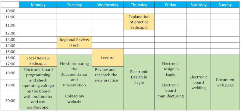
I have developed a weekly work plan that I describe in the following calendar.
1. Group assignment
Go to the Sedicupct website
2. Individual Assignment
Redraw one of the echo hello-world boards
I have used the software Eagle to make the design of my electronic board. I followed the following tutorial
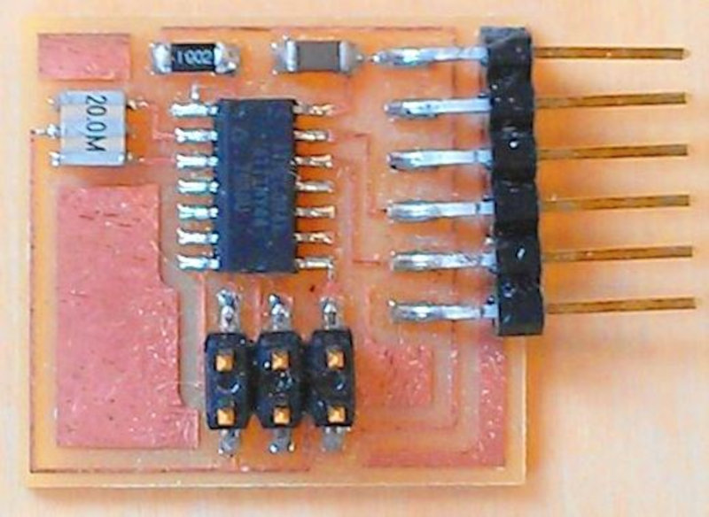
I have used the ATtiny (helloftdi.attiny44) , to create my helloboard and I am going to include a button, a led and a resistor.
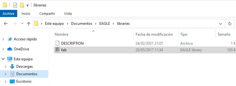
The first thing is to download the FabLab libraries for Eagle.
This is the updated fab eagle libraries on fabcloud.
Unzip the FabAcademany-Resources folder. Look in (File) and copy the files (fab.lbr - fabmodule.dru). Save the file (fab) in Documents / EAGLE / libraries. Save the file (fabmodule) in Documents / EAGLE / design rules.
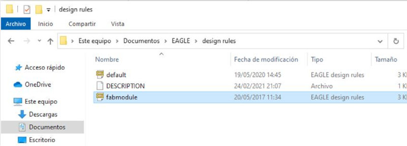
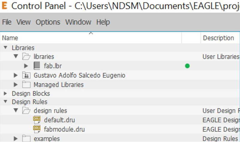
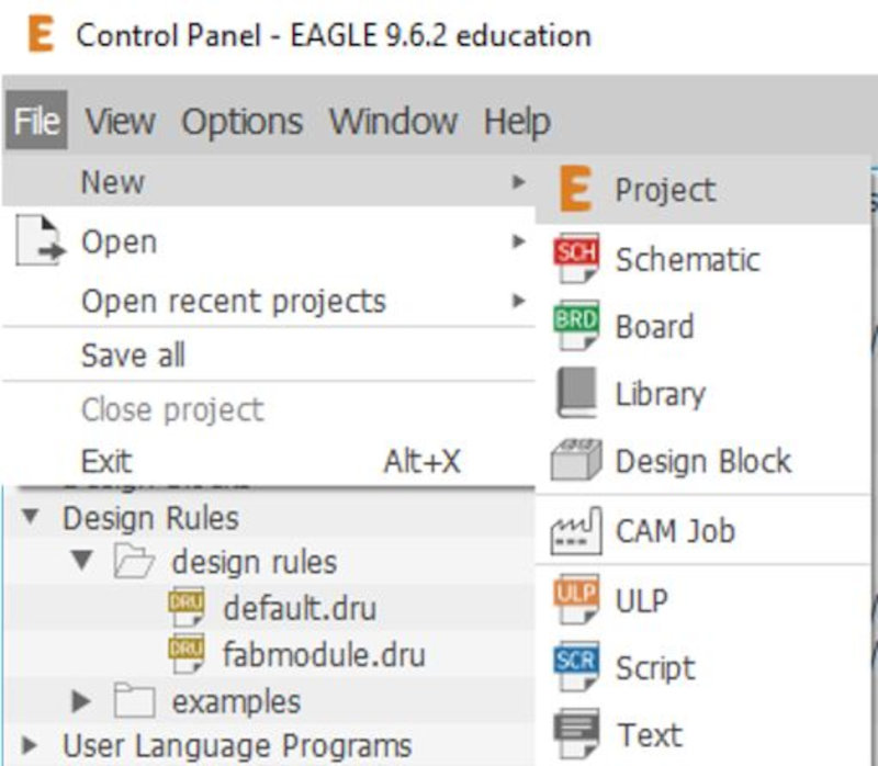
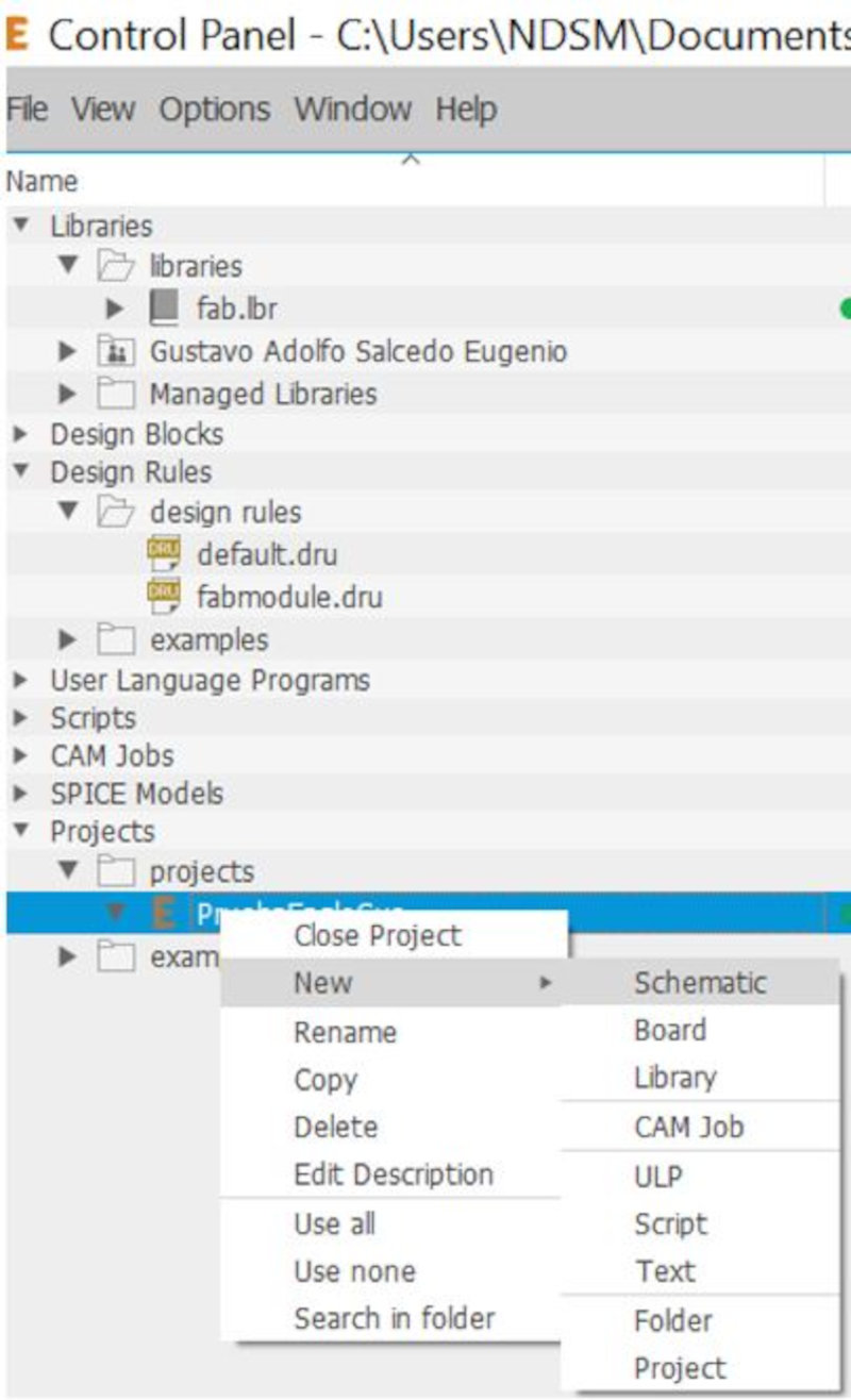
Open the EAGLE program. Activate the library "fab.lbr" by clicking on the circle so that it turns green. Verify in Design Rules that there is the file "fabmodule.dru. Create a new Project.
Create a New Scheme. Include components in the schematic.
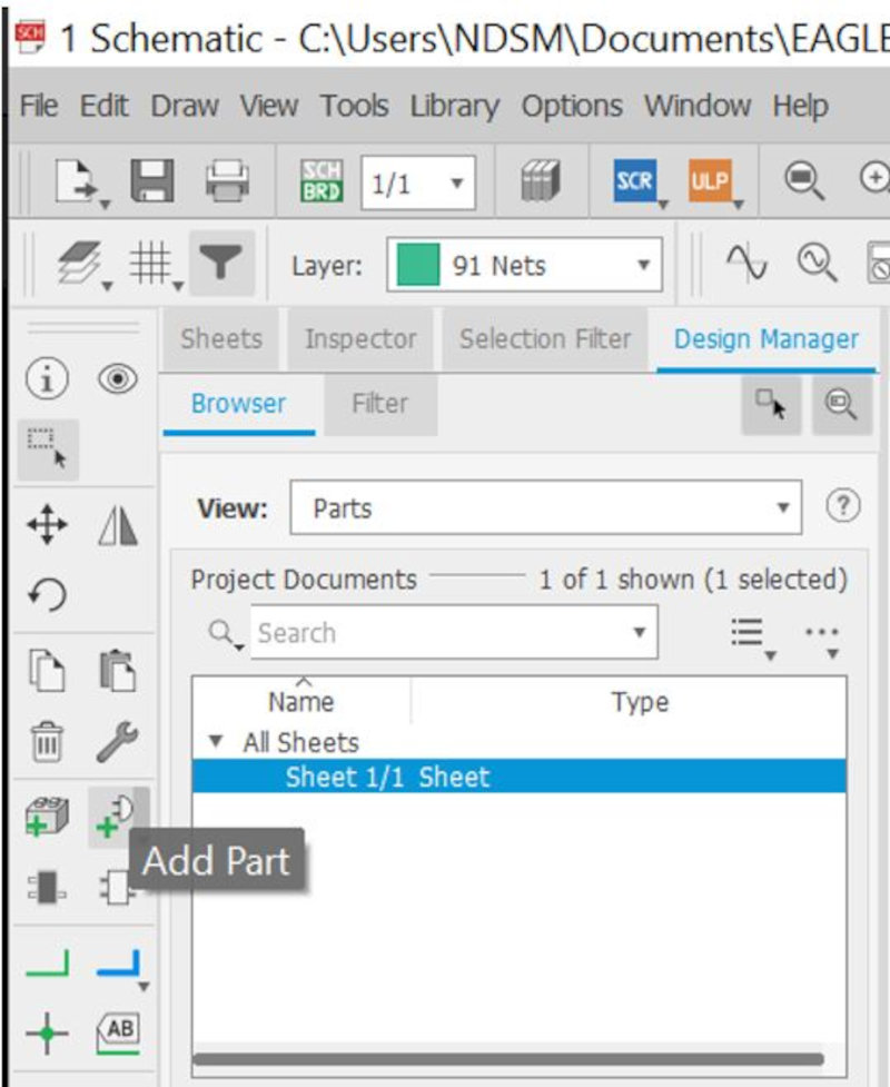
Open the "Fab" Library.
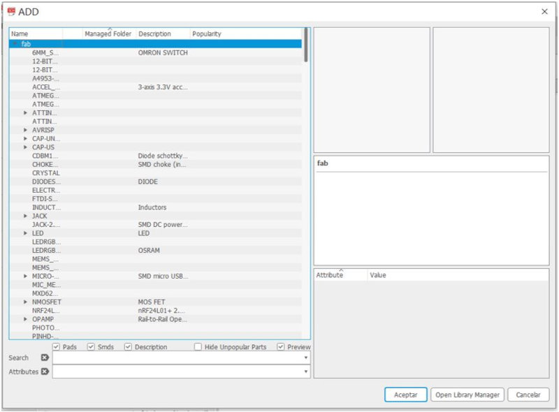
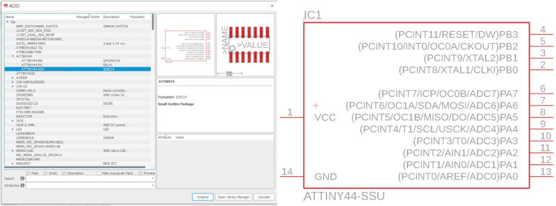
Attach the microcontroller (ATTINY44-SSU). Datasheet
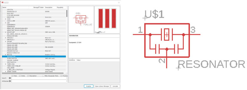
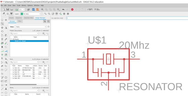
Include Resonator 20Mhz
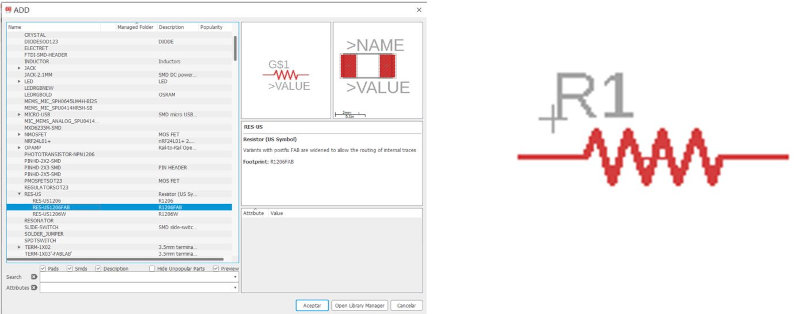
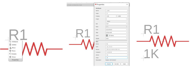
Include Resistor (RES-US / RES-US1206FAB). 499Ω / 10KΩ
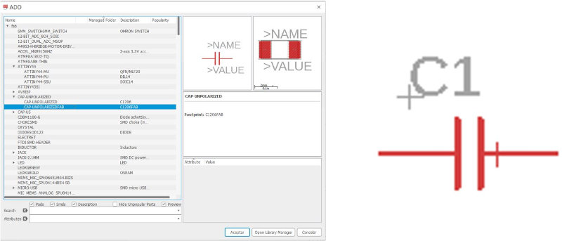
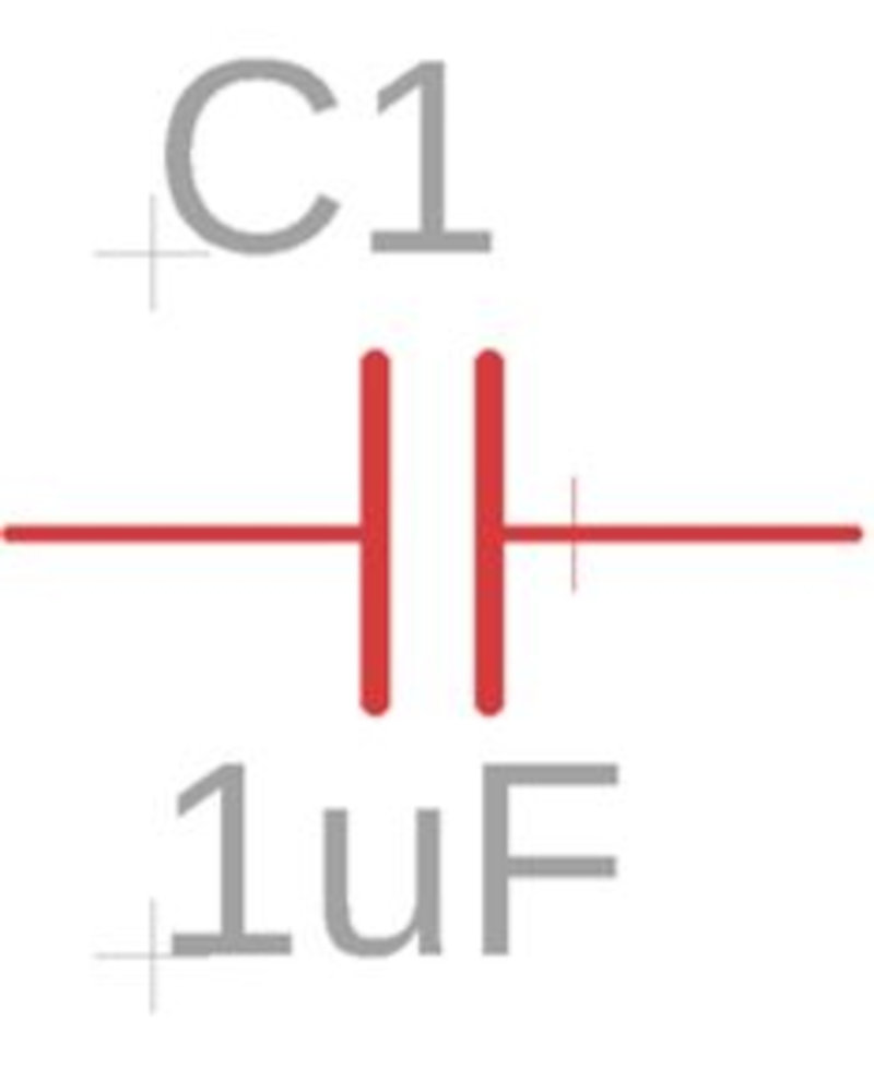
Include Capacitor (CAP-UNPOLARIZED / CAP-UNPOLARIZEDFAB). 1uF
FTDI connector (FTDI-SMD-HEADER) and Pin 2x3 (AVRISP / AVRISPMD).

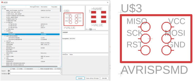
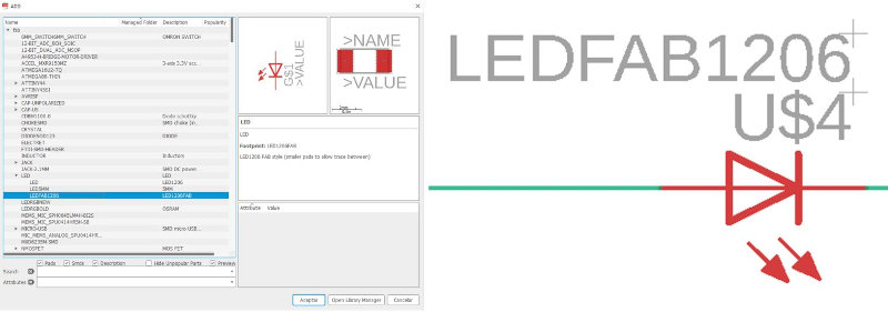
Include Pin 2x3 (AVRISP / AVRISPMD) and LED (LED / LEDFAB1206)
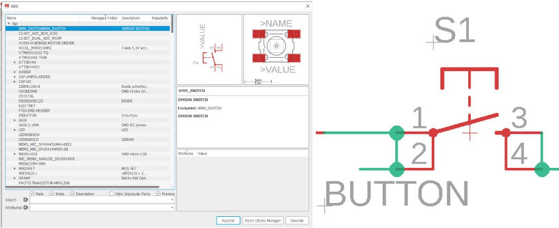
Include Button.
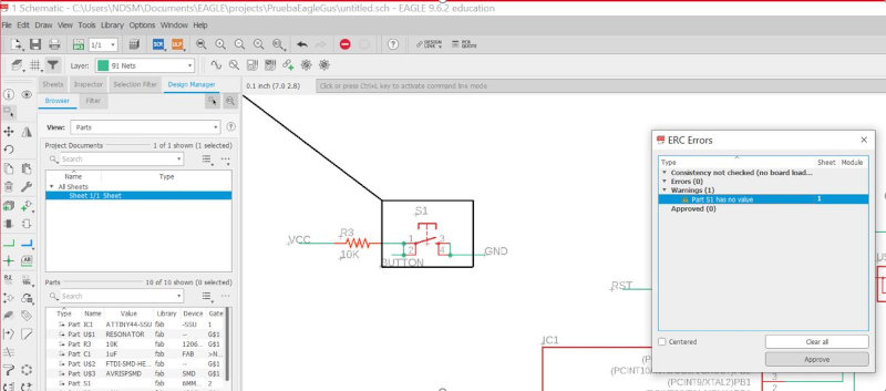
Approve Error botton value.
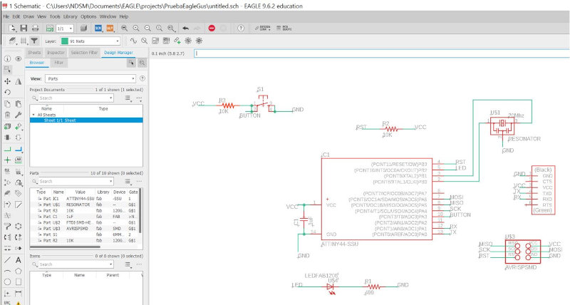
Final scheme.
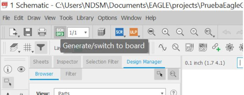
Generate switch to Board.
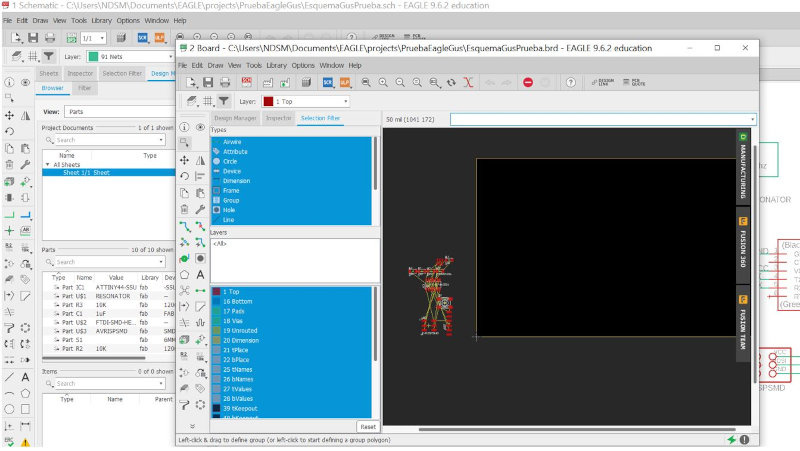
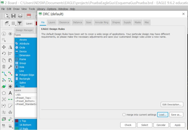
Load fabmodule.
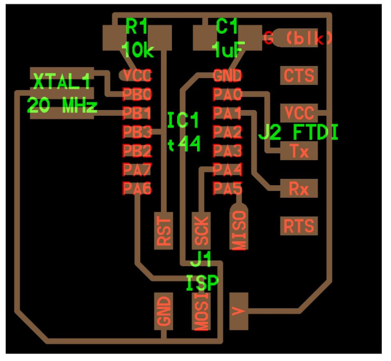
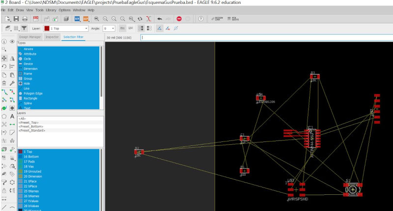
Move and place the electronic components on the board.
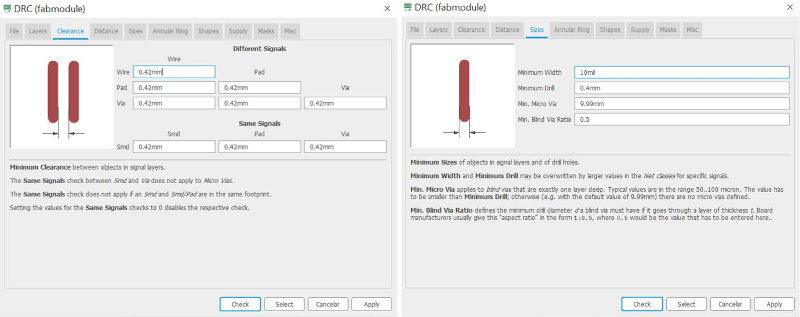
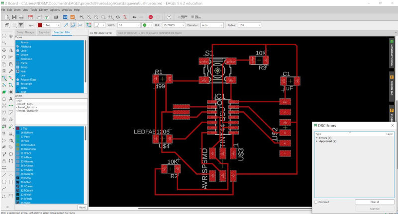
draw the lines of the tracks with the router airwire tool and check DRC.
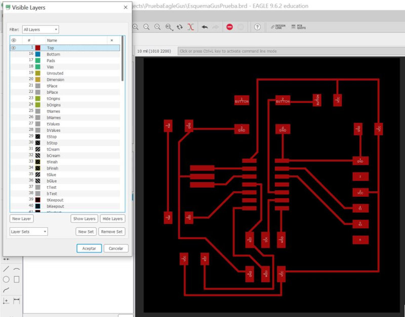
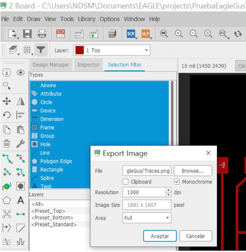
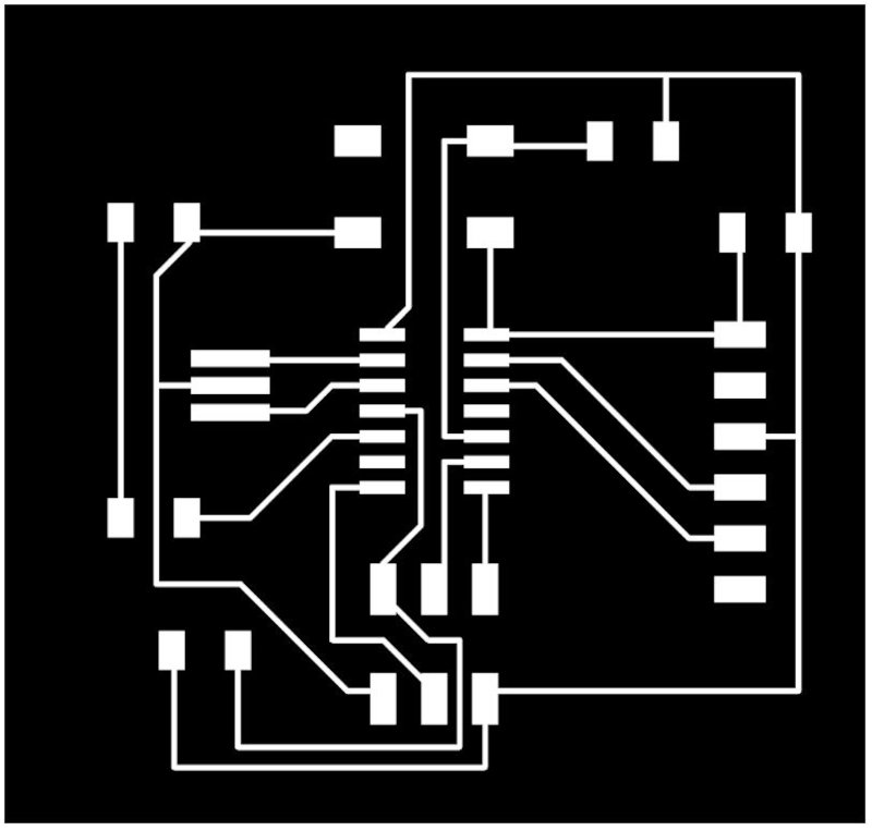
Visible Layes and select Top layer.
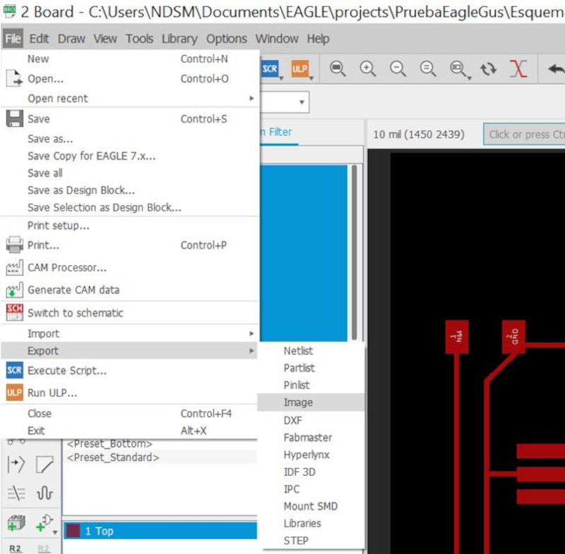
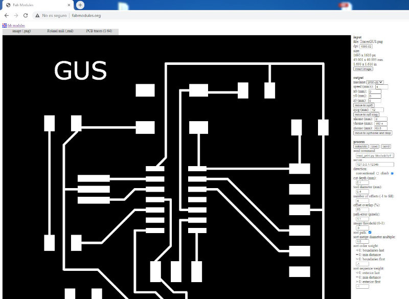
Export Image (.png), Monochrome, Resolution: 1000dpi.

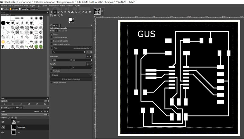
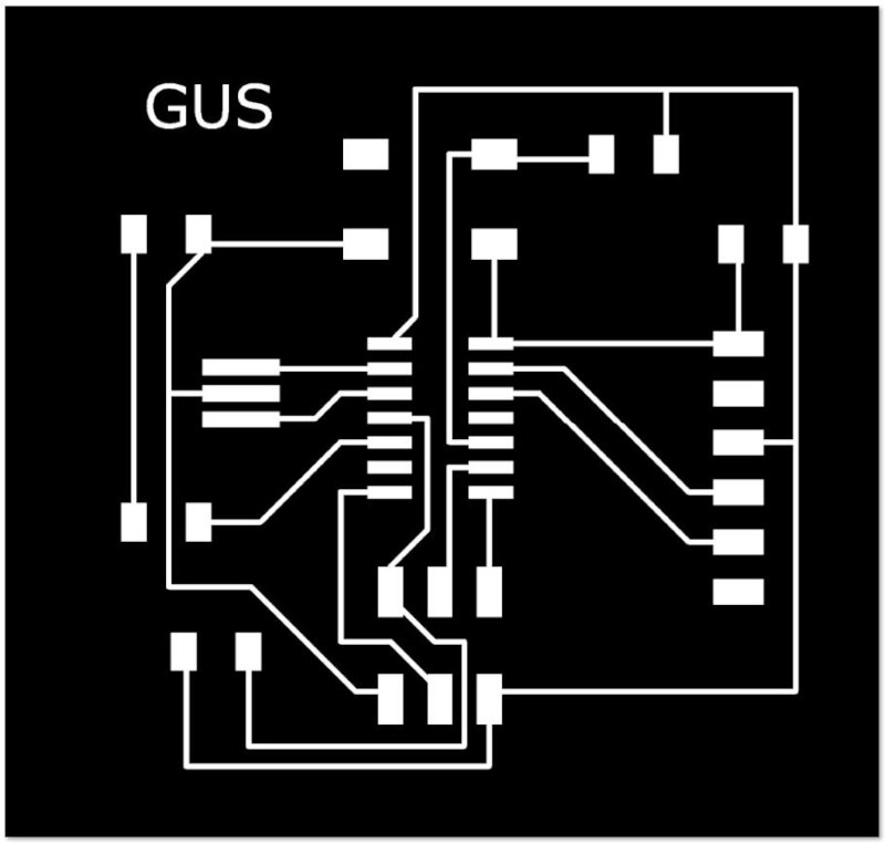
Include text with Gimp software.
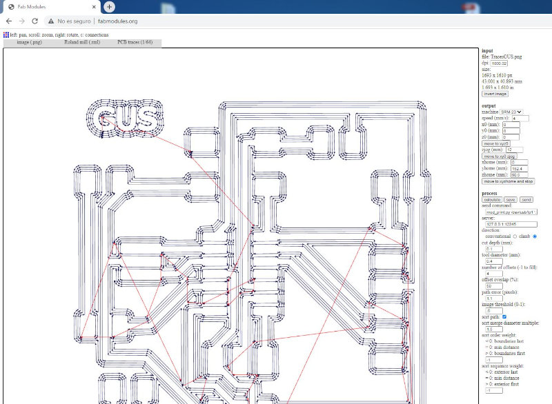
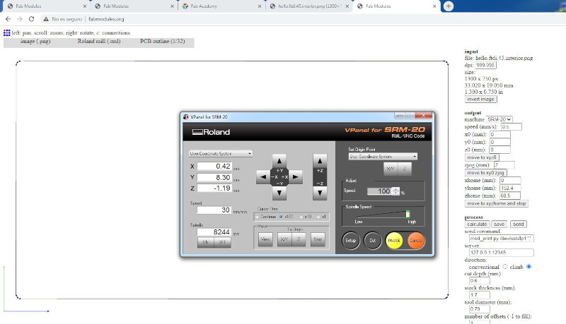
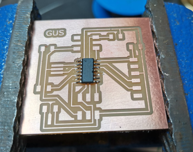
Milling
Open the link Fabmodules.org to use the SRM-20 milling machine. It is outdated and replaced by:


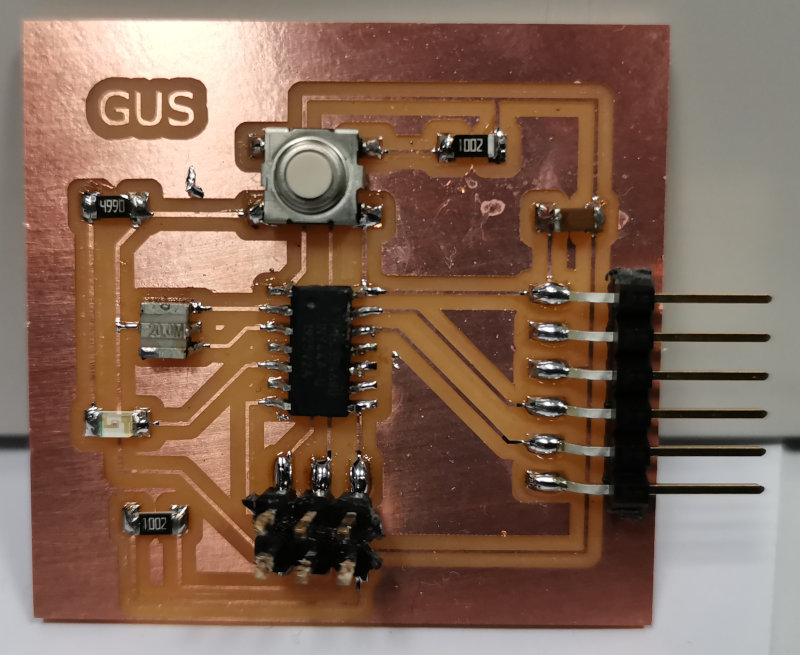
Solding
Use a template to organize electronic components.
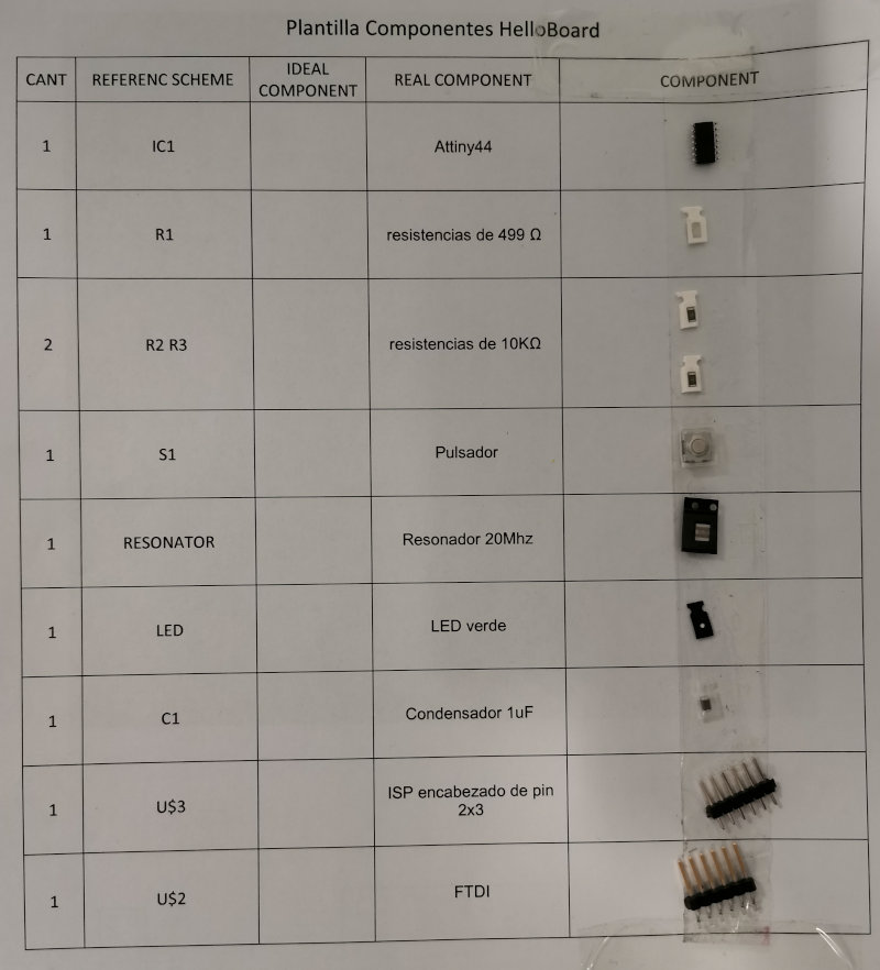
Initially solder the Atiny44, then the smaller components and finally the ISP.
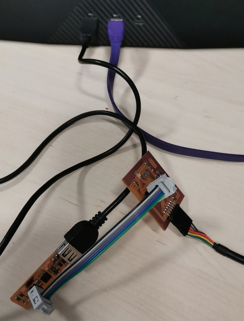
Programming
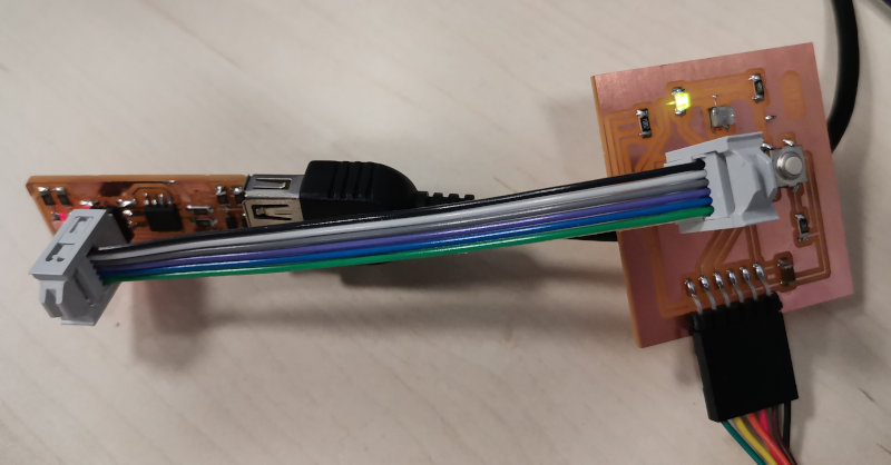
I used my ATtiny45 programmer from week 4 "Electronics Production" and plugged it into the usb port of the computer. Connect the ATtiny44 helloboard to 5vdc using the FTDI connector. Through the ISP connectors connect my programmer with the helloboard
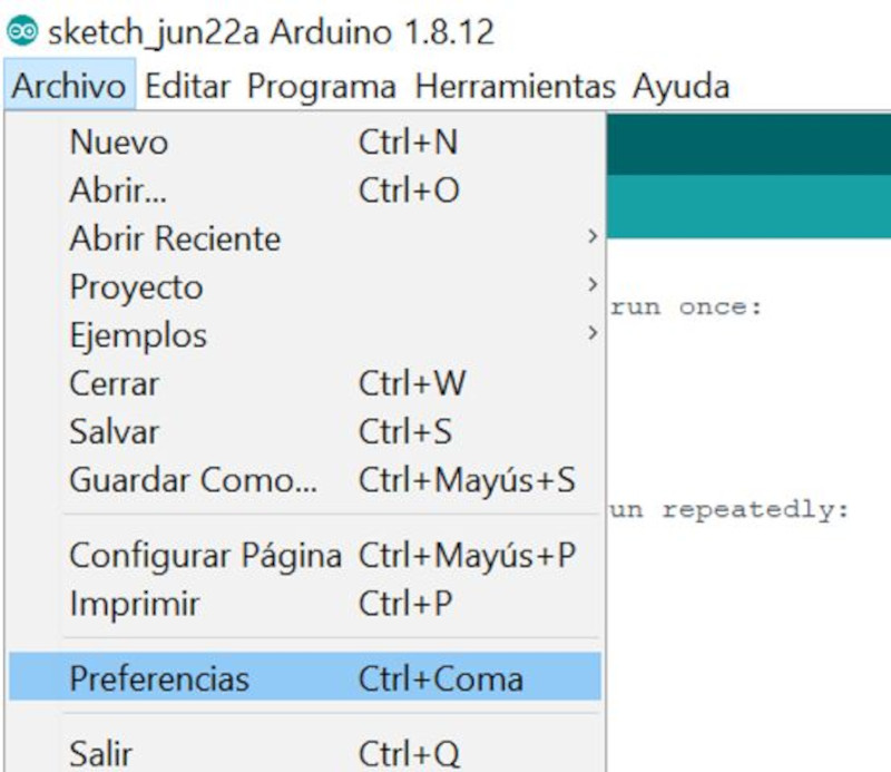
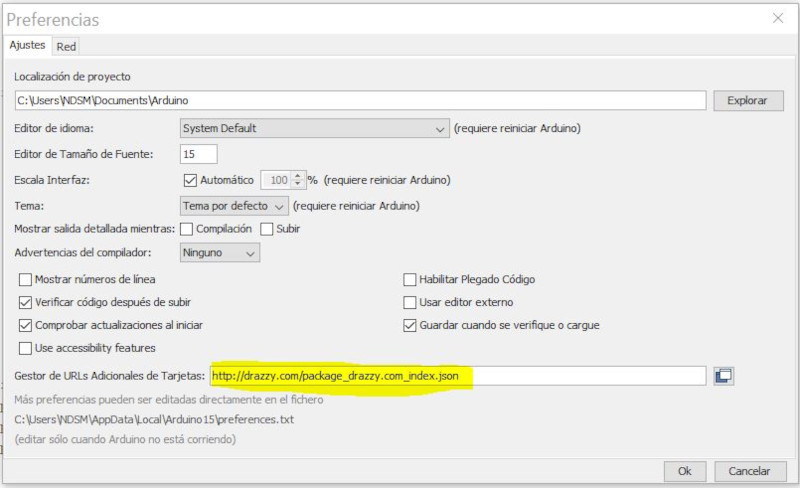
I try to use my programmer with a hello board using the Arduino IDE. Open arduino IDE, click on preferences. In manager of additional card URLs, put the following link: http://drazzy.com/package_drazzy.com_index.json. To do this, load the libraries for attiny programmers.
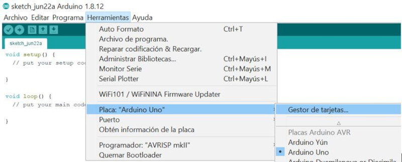
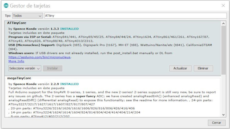
Select Tools / Board: "Arduino Uno" / Board Manager ..Type in the search engine "ATtiny" install the option "ATTinyCore by Spence Konde"
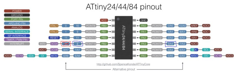
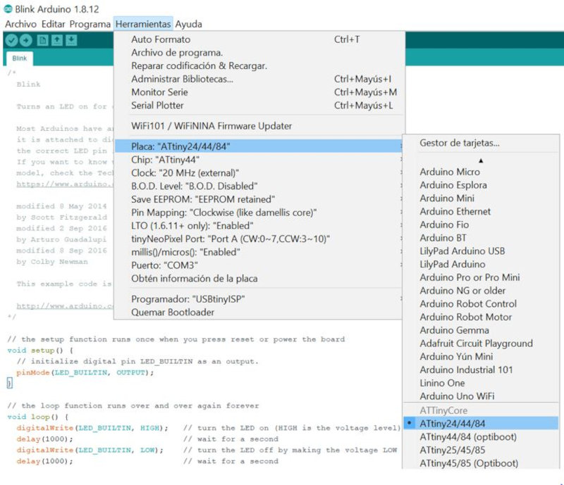
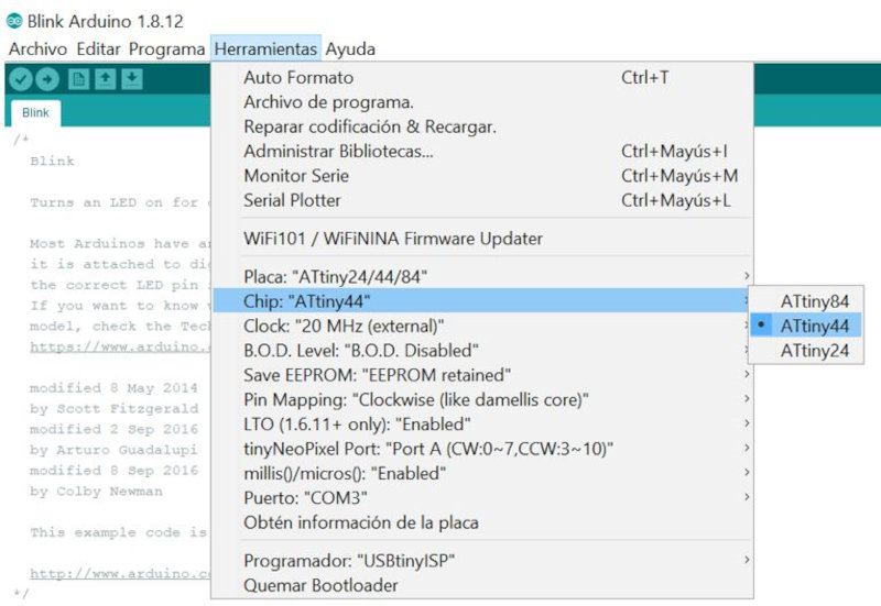
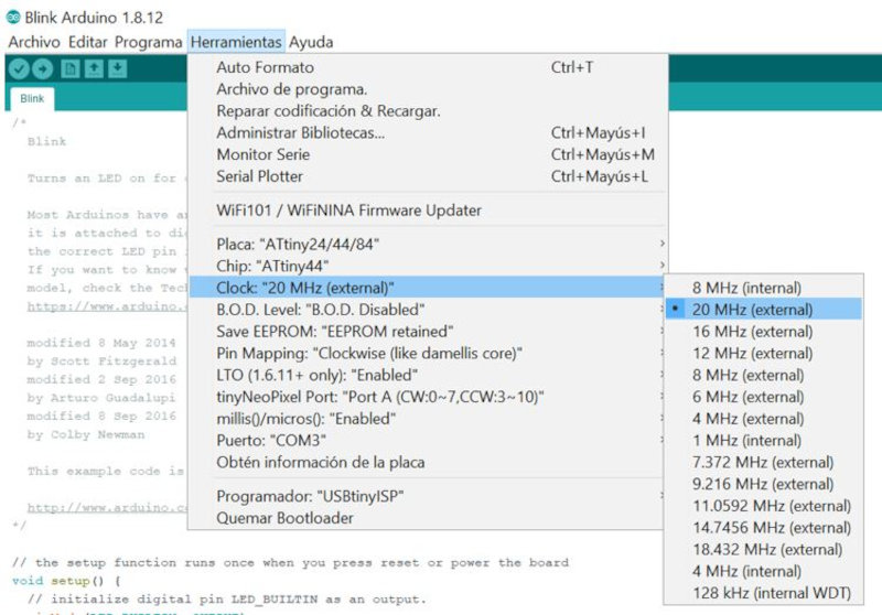
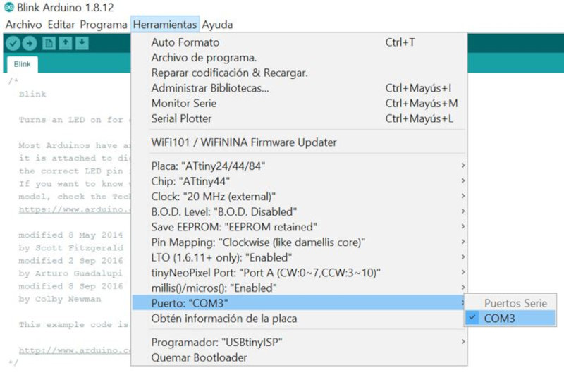
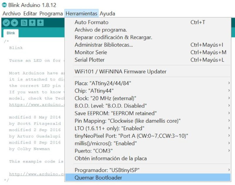
Program using ARDUINO IDE. In tools I select the ATtiny24 / 44/84 board, the ATtiny44 Chip, the Clock: "20 Mhz (external)", Port: COM3. Burn Bootloader.
I have created a basic program in Arduino, to turn a led on and off using a button.
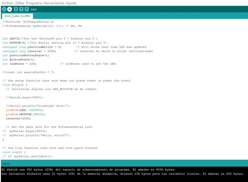
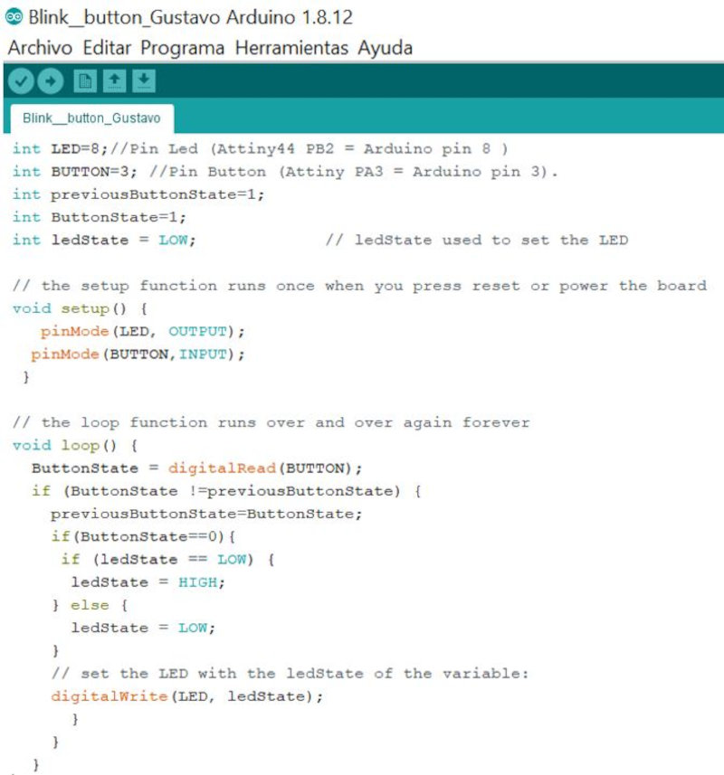
Initially I used arduino pin = 2 but it didn't work, I found it to be an alternate pin. Use main pin = 8 and it worked.