On this page, I explain the entire development process I have been doing in my final project. In it ,I count both the successes and the failures that I have encountered along the way.
I hope you enjoy reading this page as much as I have enjoyed doing the project.😊😊
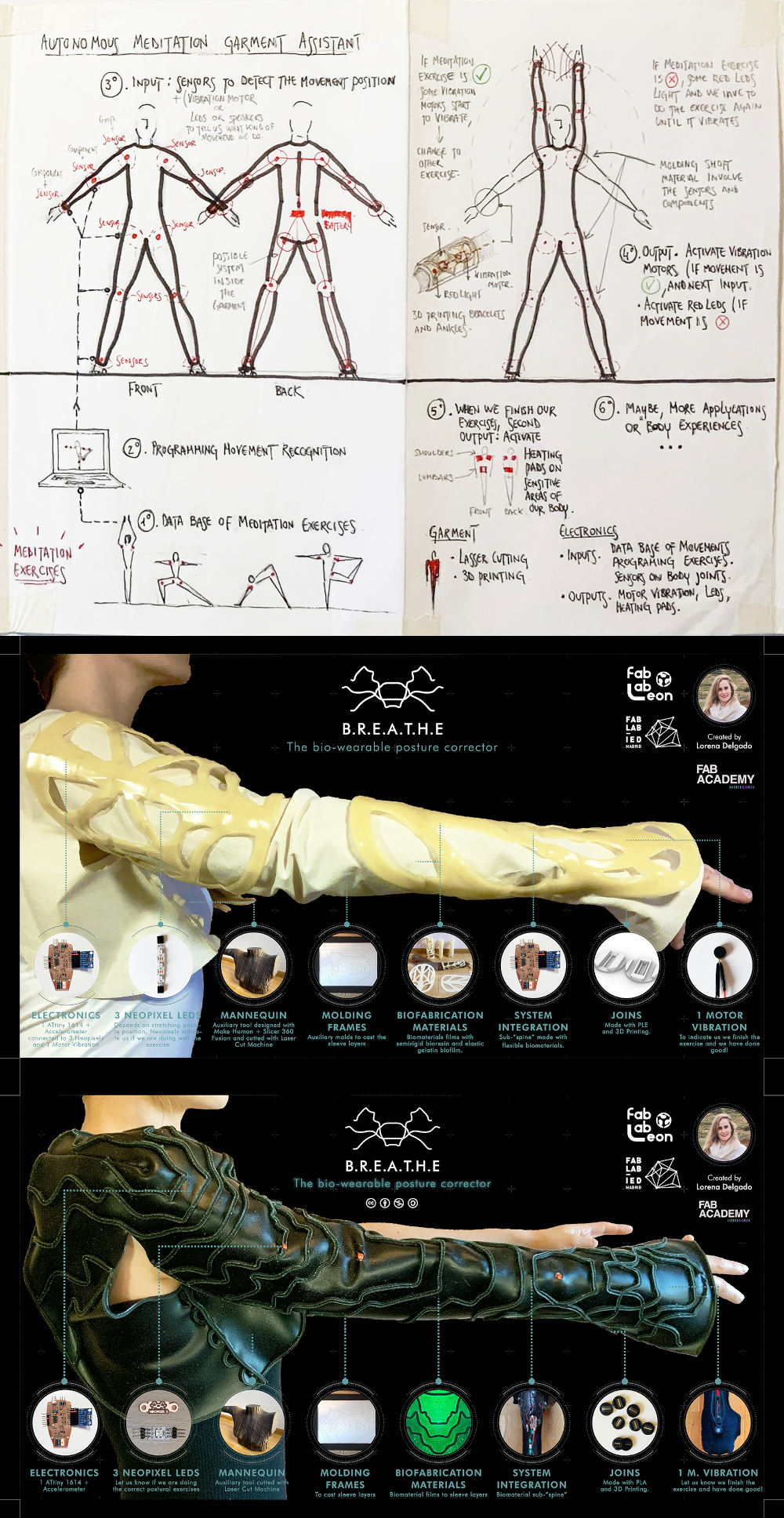
To begin, I want to show you an image of how the project has evolved since the first scketch of the week 0, its evolution until its final result.
During this assignment we have to answer these series of questions:
What tasks have been completed, and what tasks remain?
What has worked? what hasn't?
What questions need to be resolved?
What will happen when?
What have you learned?
That throughout the documentation I have been answering and developing.
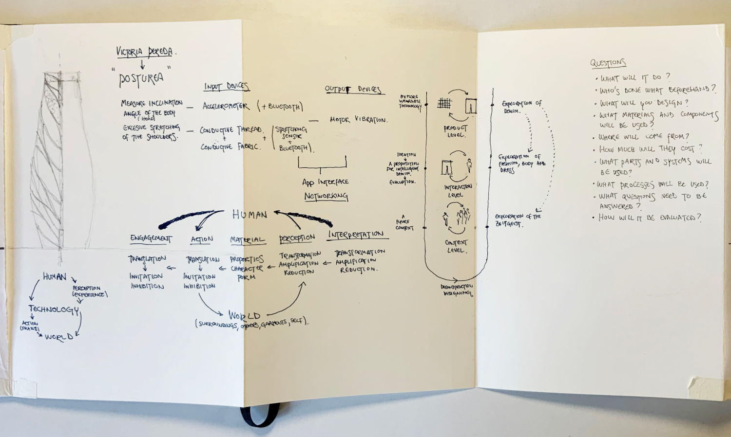
Initially, the idea of my project consisted of making a whole wearable would guide us in a series of meditation or stretching sequences. And finally, correct the body posture that we must achieve to do the exercises well.
After several tutorials with my instructor Nuria, she told me the project was too ambitious and it had many development spirals, that in a Fab Academy course I would not have time to solve. 😅
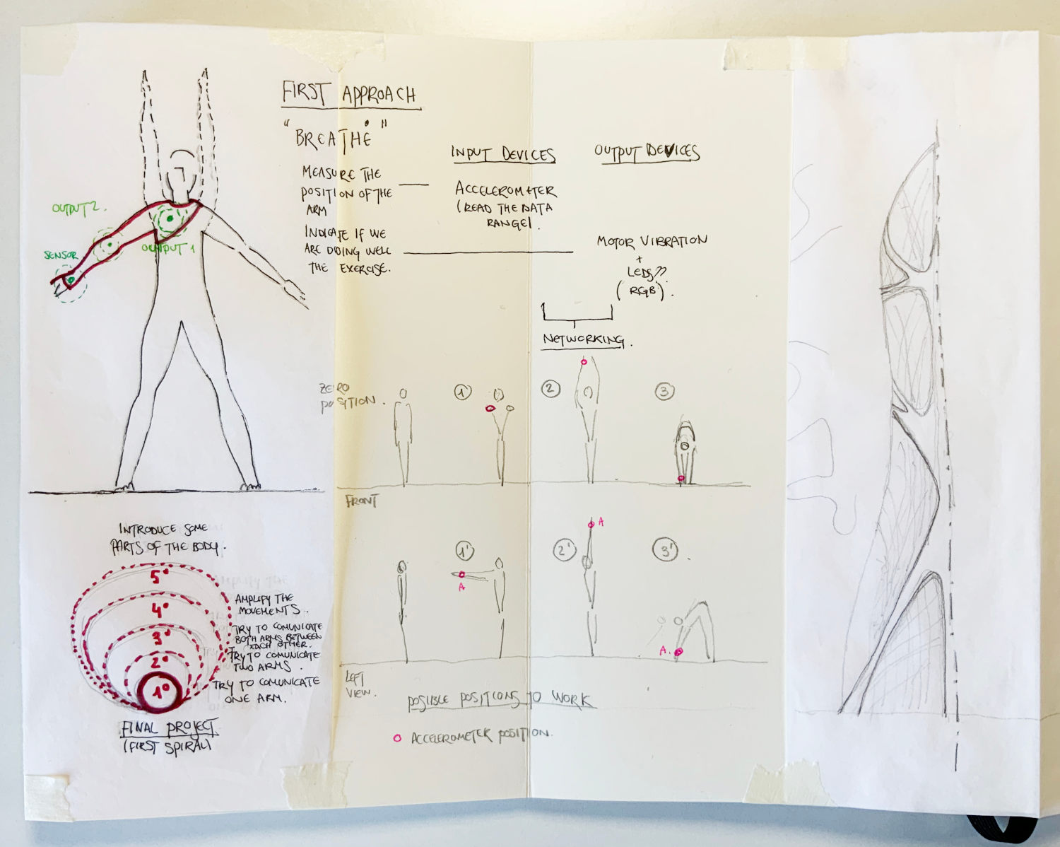
So she convinced me to focus on the first spiral, which was to be able to record the data of some meditation movements in a small sequence with one arm.
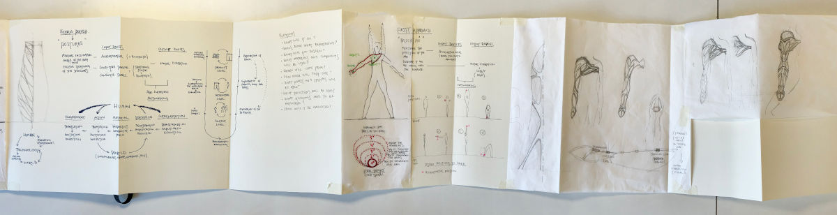
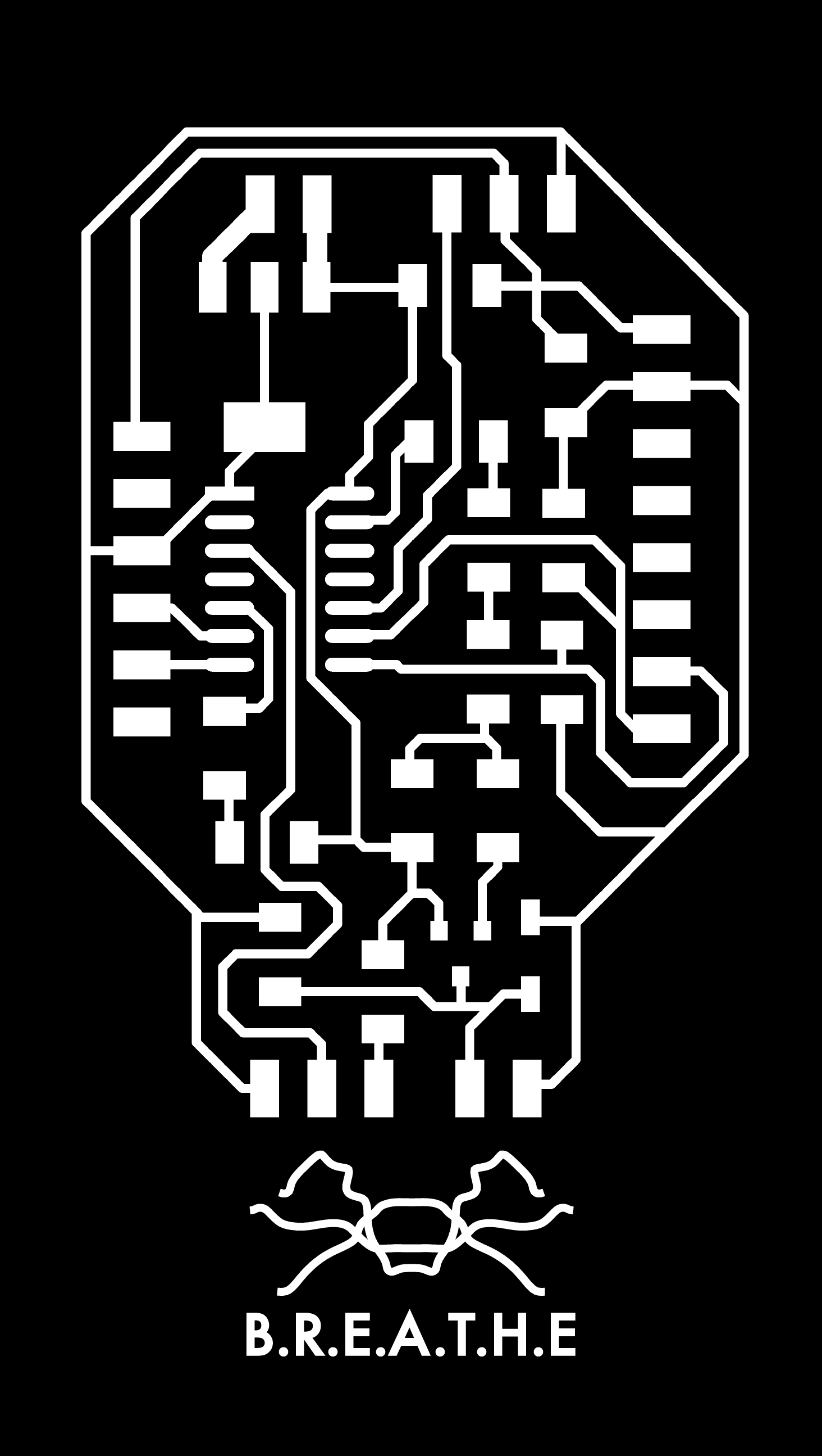
To begin, I started to drawing what would be the area of action of the project and the sequence of basic movements with which I am going to work. For this project I am going to start working around the right arm and I am going to program a sequence of basic stretching movements where breathing is very important.
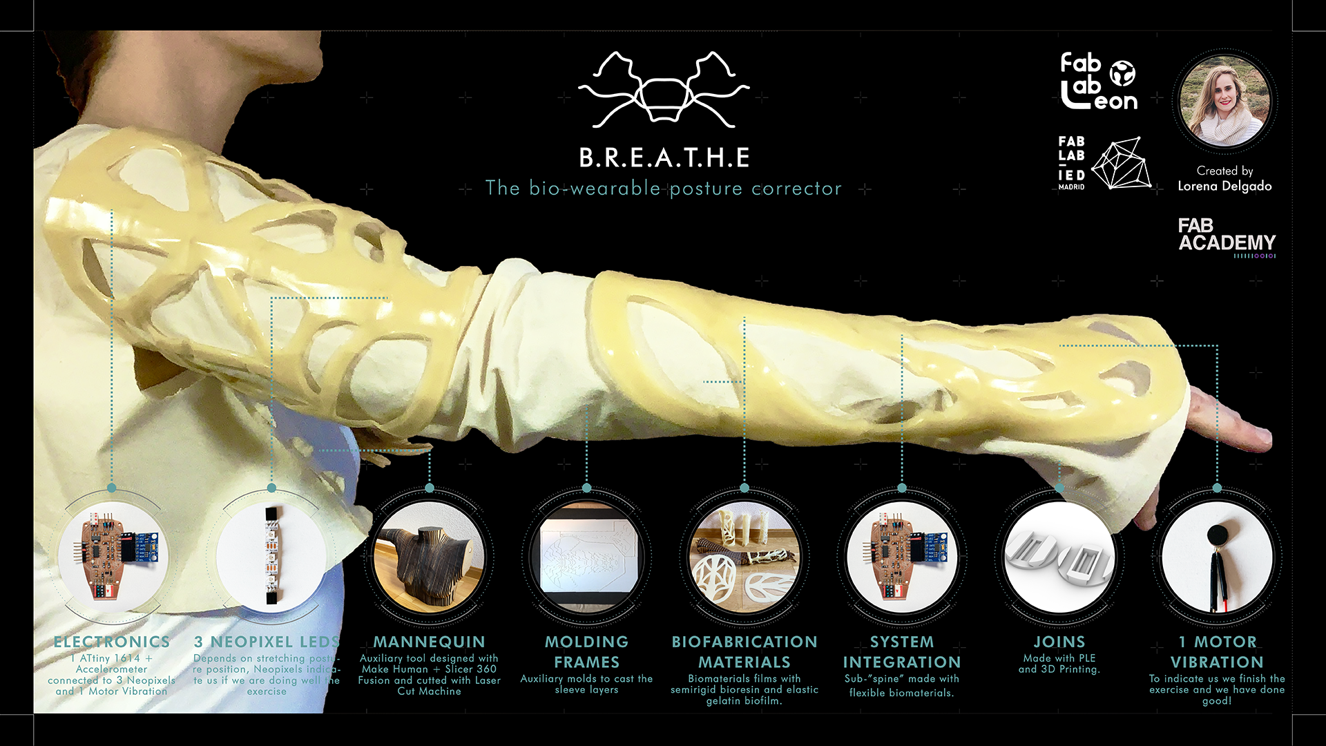
From here, comes the final name of the project B.R.E.A.T.H.E 😊
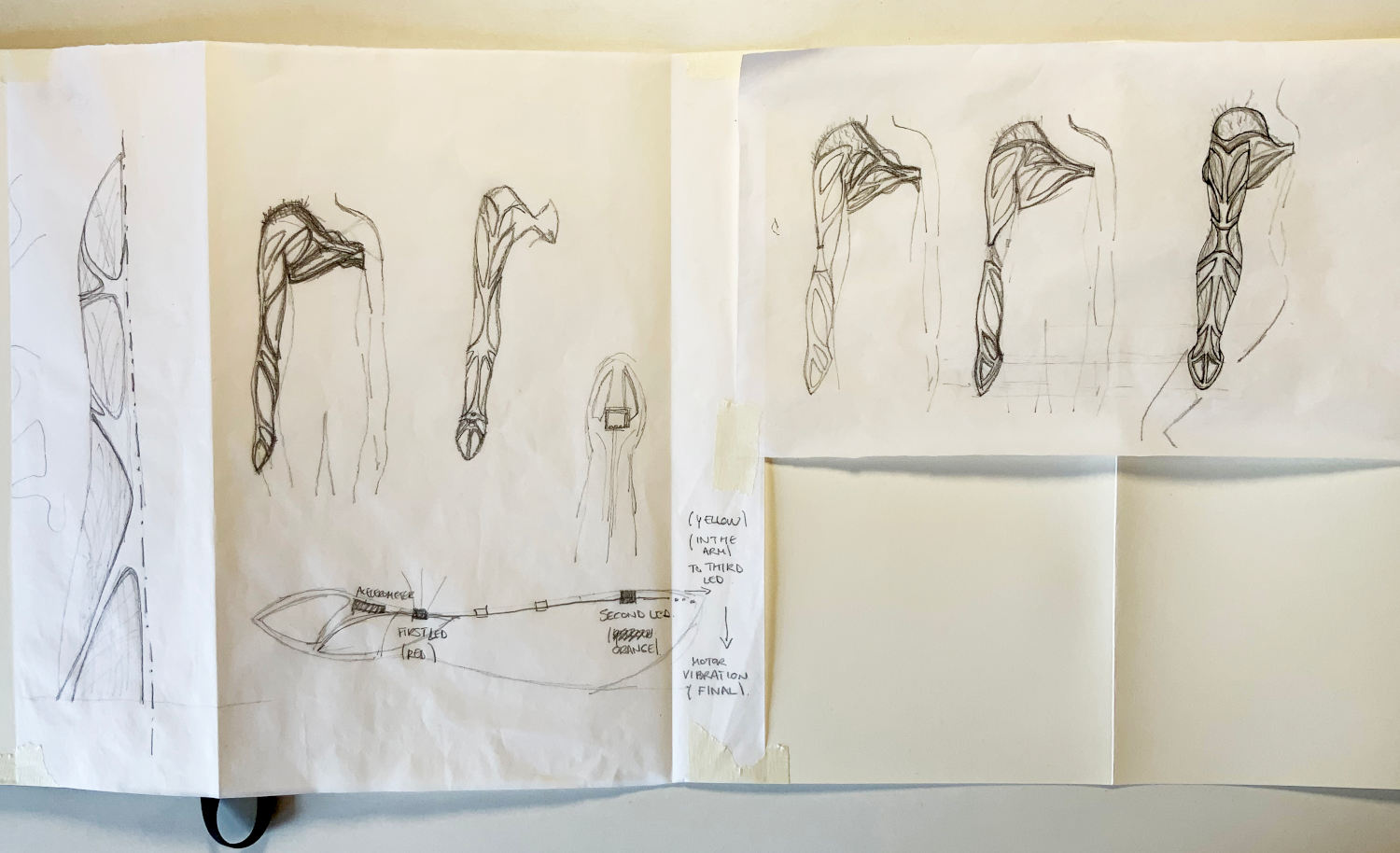
I am a great enthusiast of organic shapes, which together with my passion for biomaterials, leads me to innately draw organic structures.
As part of my background as a multidisciplinary architect and current biomaterials researcher, I would like to explore the possibility of making a wearable made of various types of biomaterials around the arm and part of the bust.
I'm still not sure what kind of biomaterials I could use, I will see it over the weeks, but I am clear about the physical properties it should have around the arm.
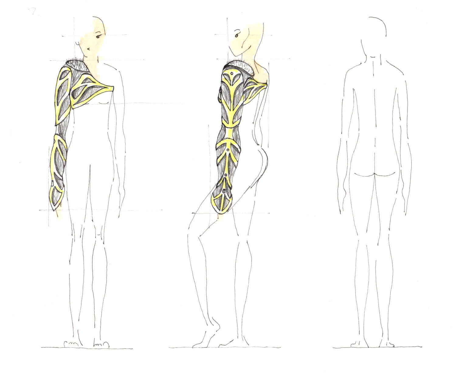
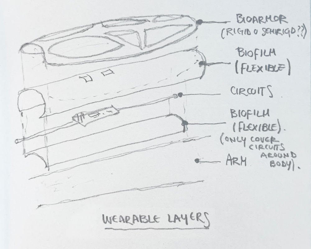
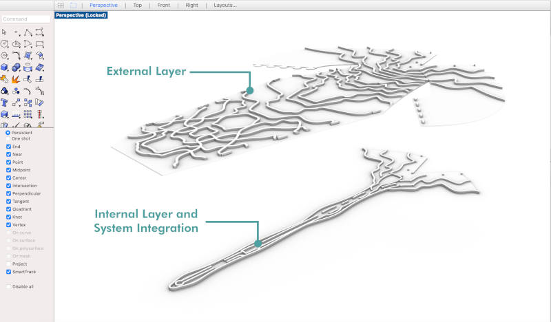
The layers that make up the project should be formed, from the inside out by:
A sublayer or "central spine", with the flexible biomaterial where electronics will be integrated.
An intermediate layer, also made of flexible biomaterial, that surrounds the entire arm and covers the electronics.
And finally, event the electronics are transparent due to the flexible biofilm, an upper layer of rigid or semi-rigid brazers that cover the entire system and provide the aesthetic factor of the project.
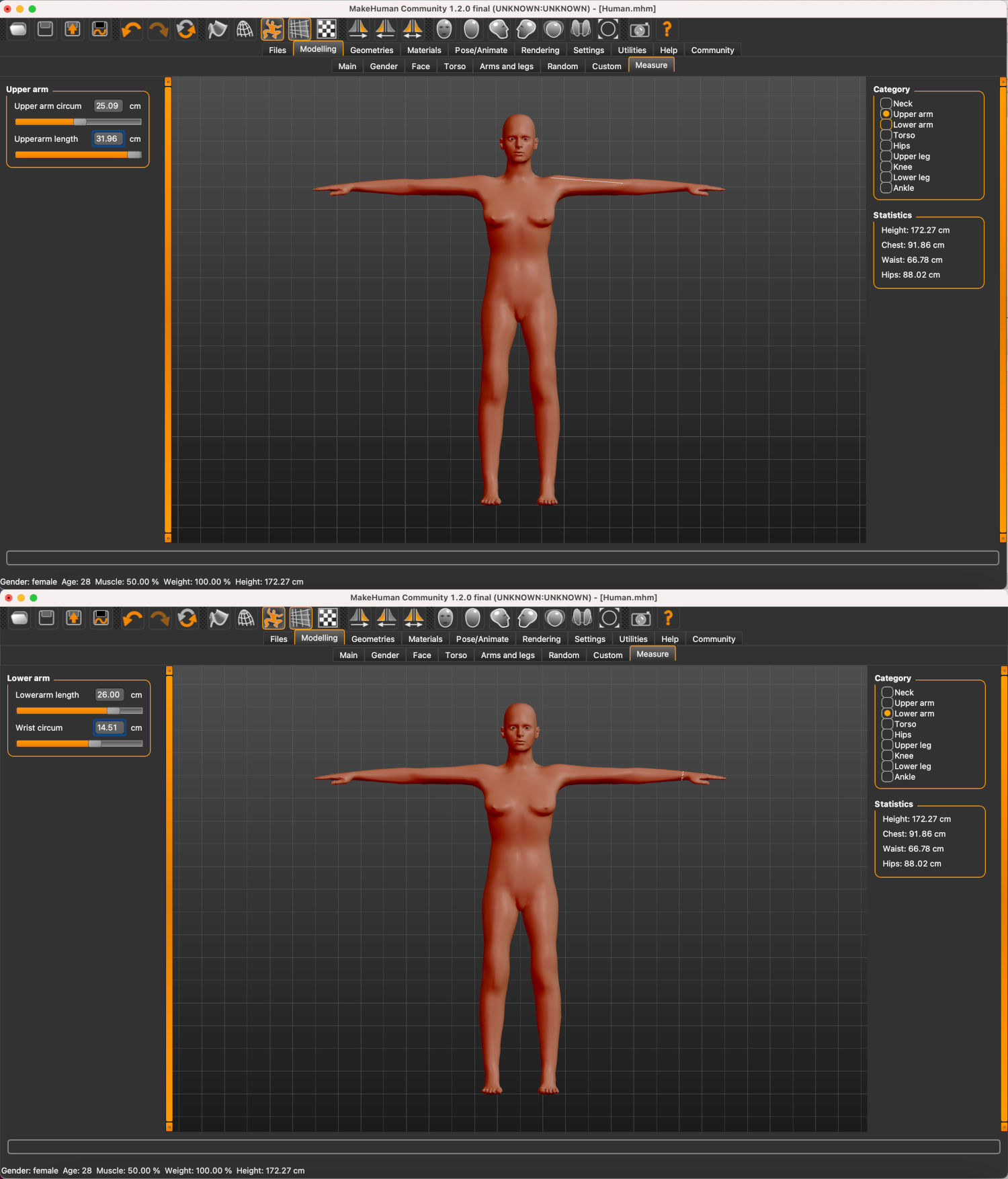
To start with the design, I need a virtual human model and a physical mannequin with arms to help me model the suit around the figure (at home I only have mannequins without arms 😅). For this, I have used Make Human, a software that allows me to create personal human models and postures.
In this model, I will adapt the figure to my real personal measurements for a better adaptation of the sleeve to my body.
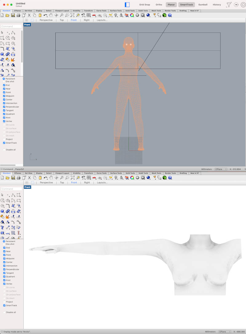
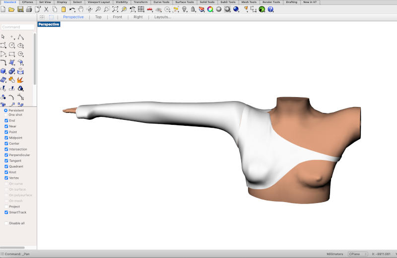
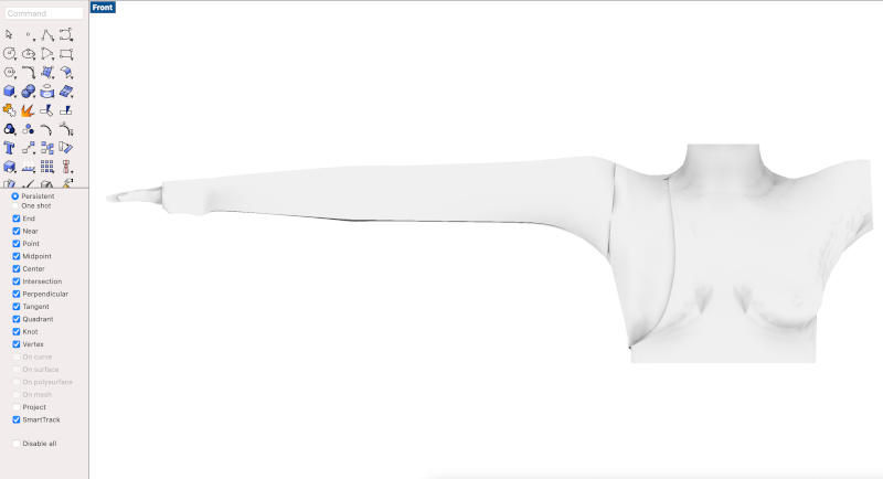
Once I have the model, I export it the file to Rhinoceros, and with surfaces I cut the parts of the solid body that I will not need, to keep the bust and the right arm.
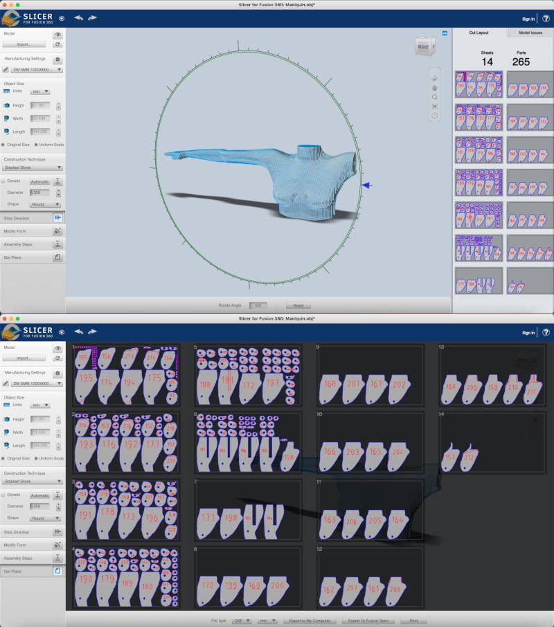
Once I have it, to make the physical mannequin, I am going to use the Slicer for Fusion 360 software to obtain the layers that will make up my final mannequin.
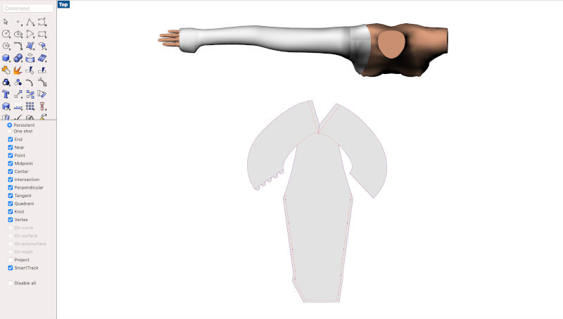
The first prototype I made, more or less, it was exactly to the initially draw I had creating. With a series of irregular surfaces that formed the sleeve and bust of the suit.
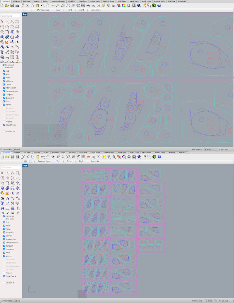
Once I had the 3D model drawn, I proceeded to make a Smash command, in Rhinoceros, that flattens the 3D irregular shapes to 2D surfaces. The initial results of the surfaces when I ran the command were a bit strange. 😕 So after several hours of modification, readapted of the patterns in 3D and 2D, I obtained some suitable patterns to cut in the first toile.
The toile is the first design prototype that is made in fashion haute couture to adapt the patterns of the garments in cotton fabric before executing the final design with the final fabrics.
At fab lab IED Madrid, I cut the first toile in the laser cutting machine. Here you can see a short video with the process:
Once the parts were cut and sewn, between me and my sister, Leonor 🤗, she helped me to adjust the parts of the pattern that needed to better fit my body and readjust them to the design.
_Second and Final Prototype
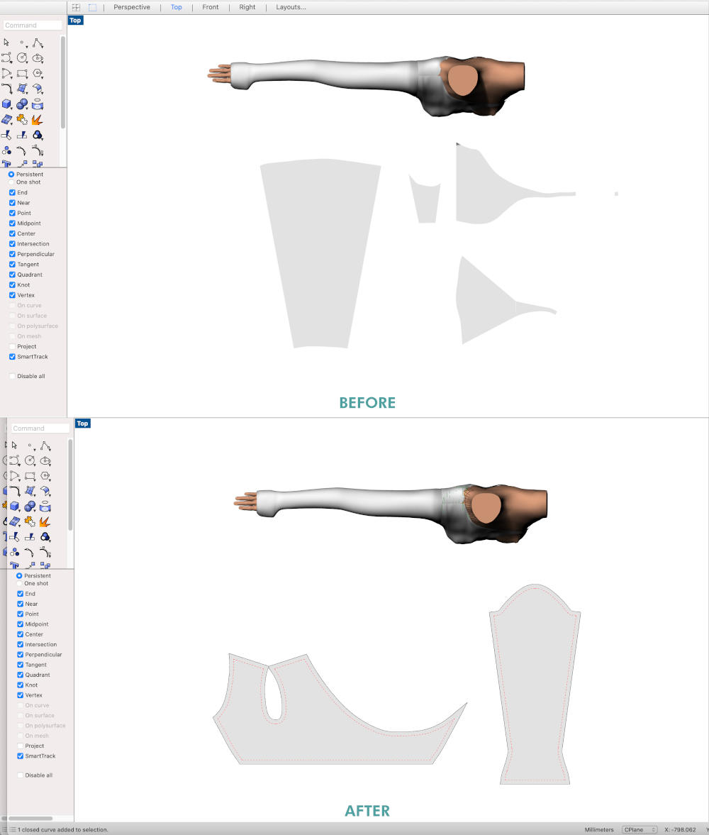
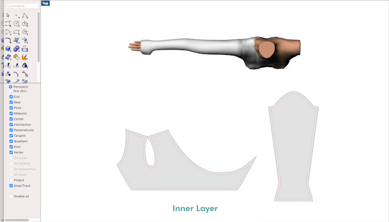
After showing the first prototype to my instructors, Adrián + Nuria + Pablo, in our local reviews, Nuria advised me to further simplify the prototype design to only the sleeve, or the sleeve and the shoulder so that I could have a firm base to hold the garment.
Guided by her advice, I readjusted the pattern of the sleeve so it would be made up of a single piece with a series of easy joints and holes to arrange some joints that I want to design and print it with the 3D printing machine.
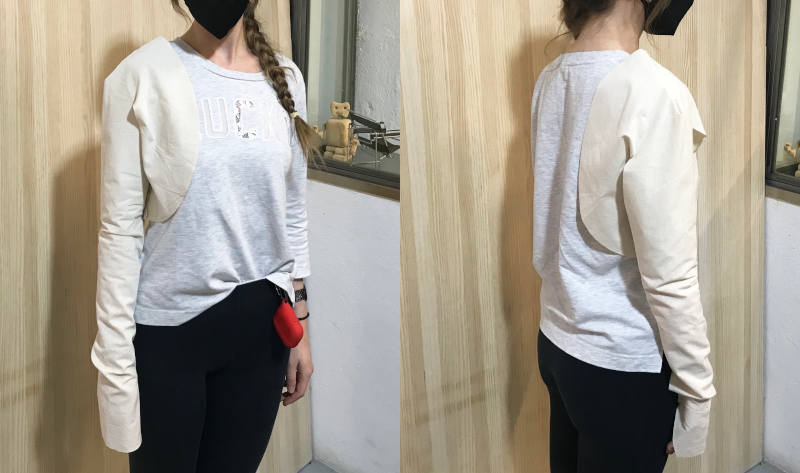
As in the first prototype, I cut a second cotton toile on the laser cutting machine. After I sewed this was the final result.
As I have described in the Evolution section, the main idea is create several layers of biomaterial around the arm that form the sleeve and well hide all the electronic system that I will integrate.
For the first prototype, and as I have already described in First Prototype section, on one hand, I have designed the intermediate sleeve that would be made with flexible biomaterial.
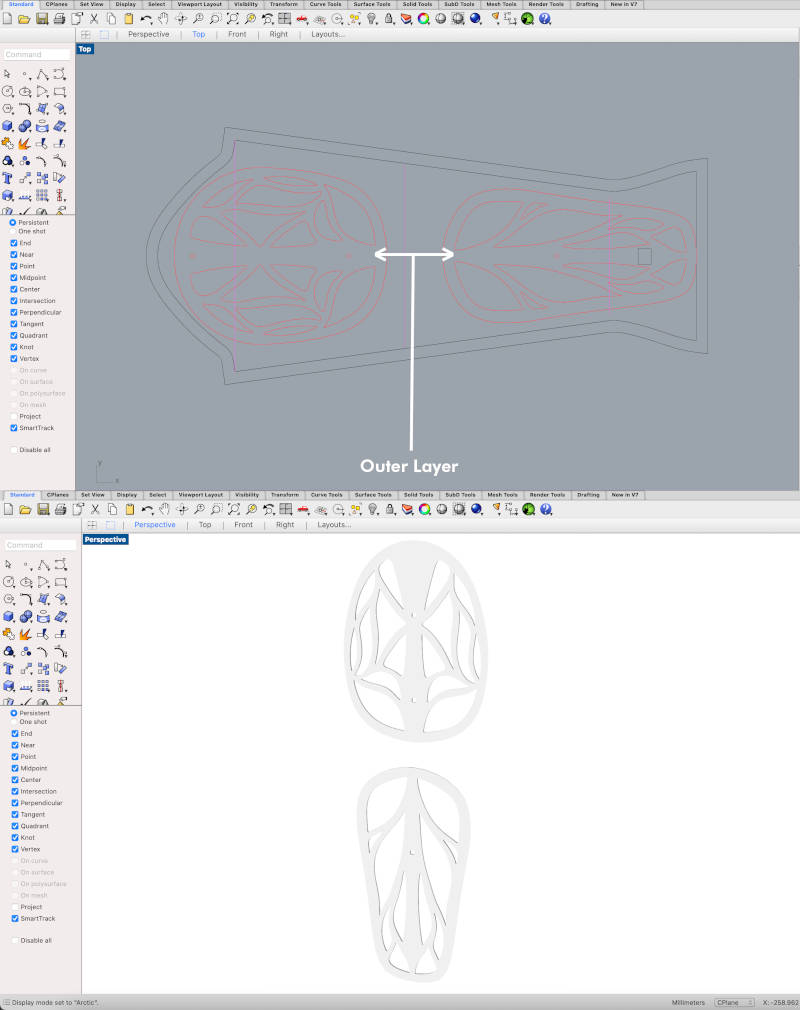
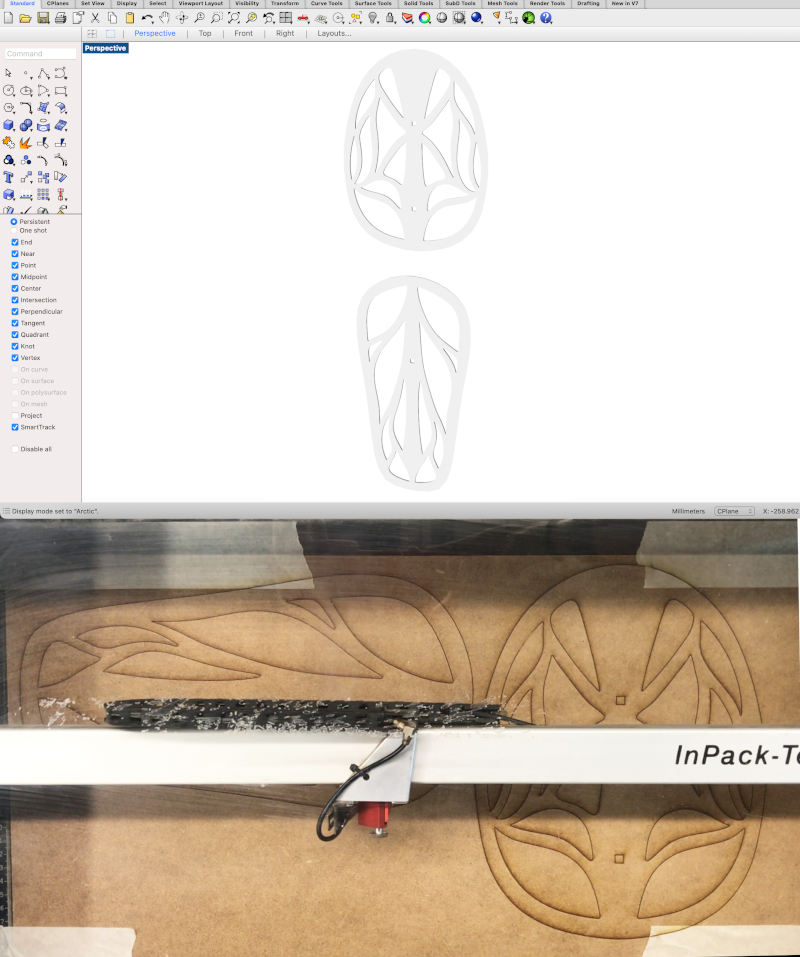
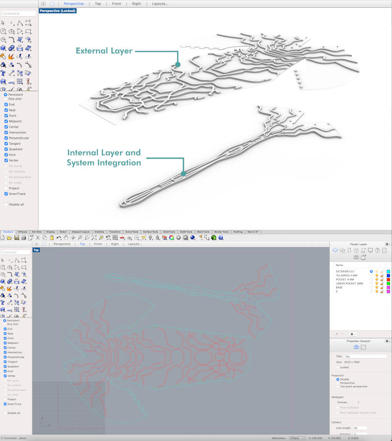
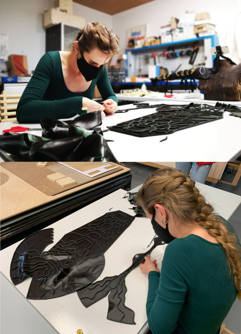
And on the other hand, in 2D, I have drawn the templates of the outer brazers that will be made with rigid or semi-rigid biomaterial. The idea of these brazers is they follow an organic structural line like the branches of the leaves. After several designs made, this was the final result of the templates.
Initially, I began to develop this pattern with Grasshopper, but the design I was developing gave me a lot of problems around the sleeve surface designed 😓, so I opted to create an invented and drawn structure.
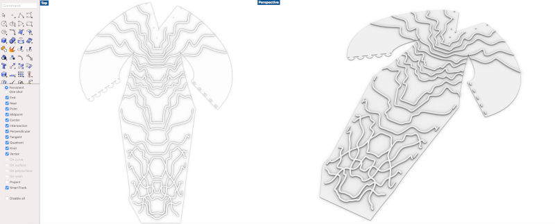
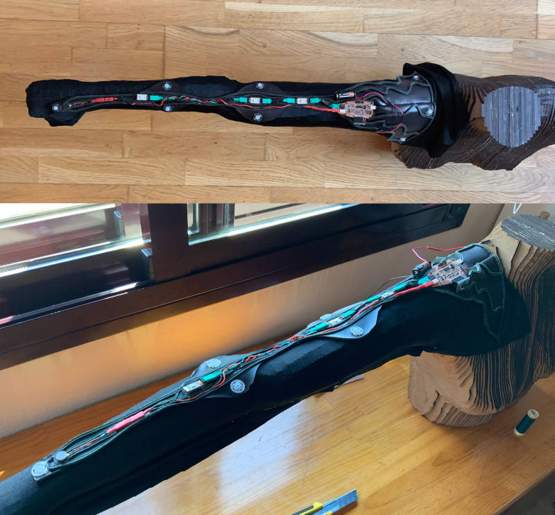
At this point, I decided to draw the internal "spine" of the wearable's electronic circuit. At this stage, it was already clear what were the number of components, the size of the electronics board and the battery that I was going to use. So, measuring each of the components, I drew the traces and contours of the components where are going to be embedded.
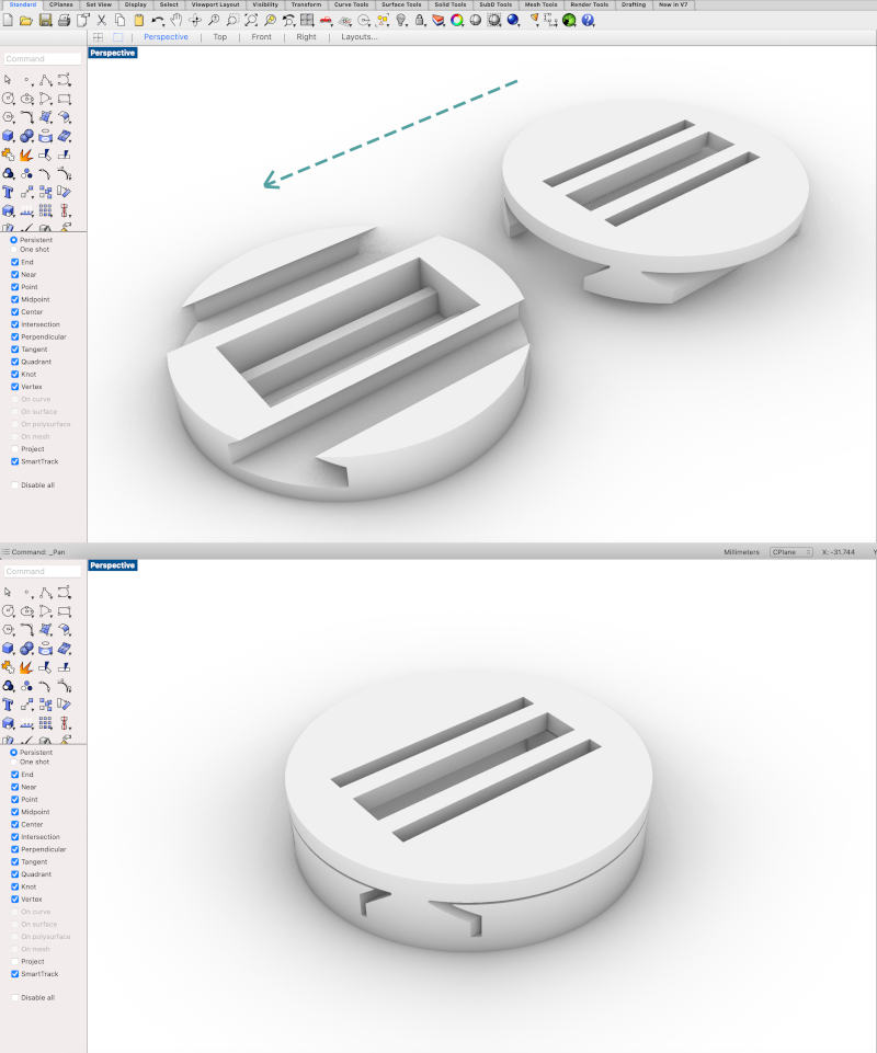
To join the ends of the sleeve, instead of sewing them, I have decided to design some simple joints in certain points of the ends of the sleeves to be able to remove and put them easily.
Their are circular pieces, with recesses inside, to be able to dovetail the pieces and their have some recesses in the center to could sew the pieces inside with the biomaterial fabric.
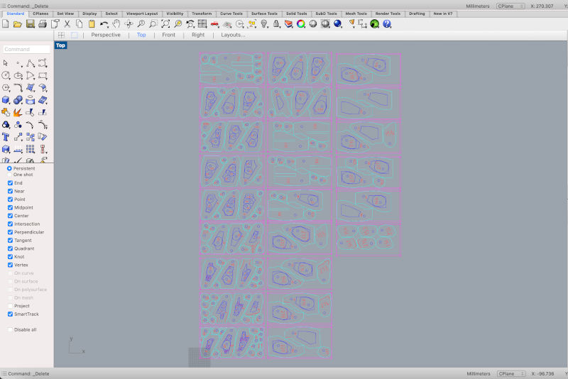
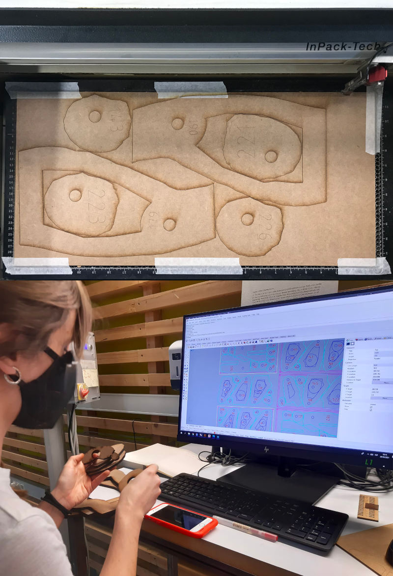
For auxiliary tools of the project, such as the mannequin and the templates of the brazers of the first prototype, I have used the laser cut machine to cut the DM wood pieces of both tools.
With the pieces obtained from Slicer for Fusion 360, and cleaned in Rhinoceros, I prepared the pieces in 24 DM boards of 600x300 mm, to be cut on the Trotec Speedy 100R laser cutting machine.
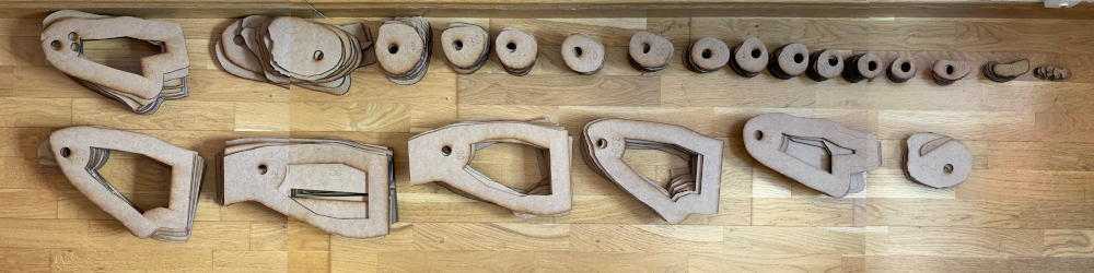
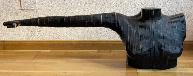
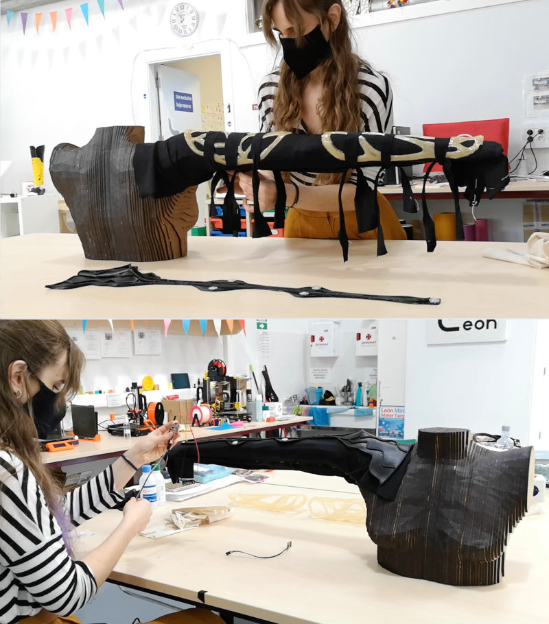
Throughout one afternoon, and with the help again of my sister, Leonor, I joined all the pieces of the mannequin, using a round wooden section inside the sections for greater rigidity and union between the part of the arm and the bust.
Here you can see the videos of the assembly process:
For the first prototype designed previously, I have cut the templates that I will use to make the molds with the vaccum thermoforming machine using 3mm MDF boards.
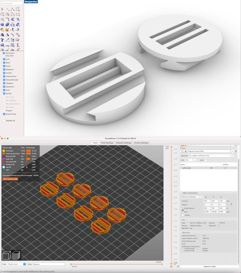
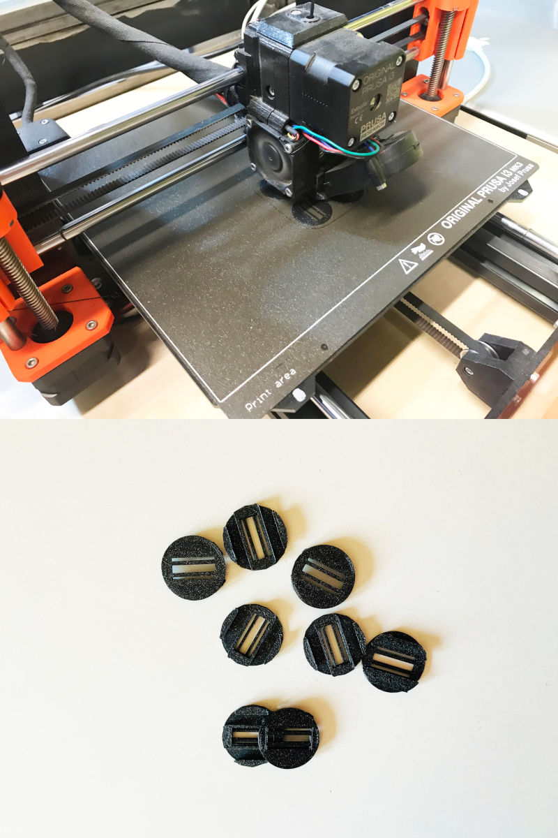
For the joint pieces of the sleeve, I used the Prusa 3D printer to get them. At first I had to do several tests of the printed parts to get the joints to fit well together.
But, when achieving the desired fit, I started to print the 8 pieces that make up the joints of the sleeve, and after almost 4 hours of printing, these are the results.
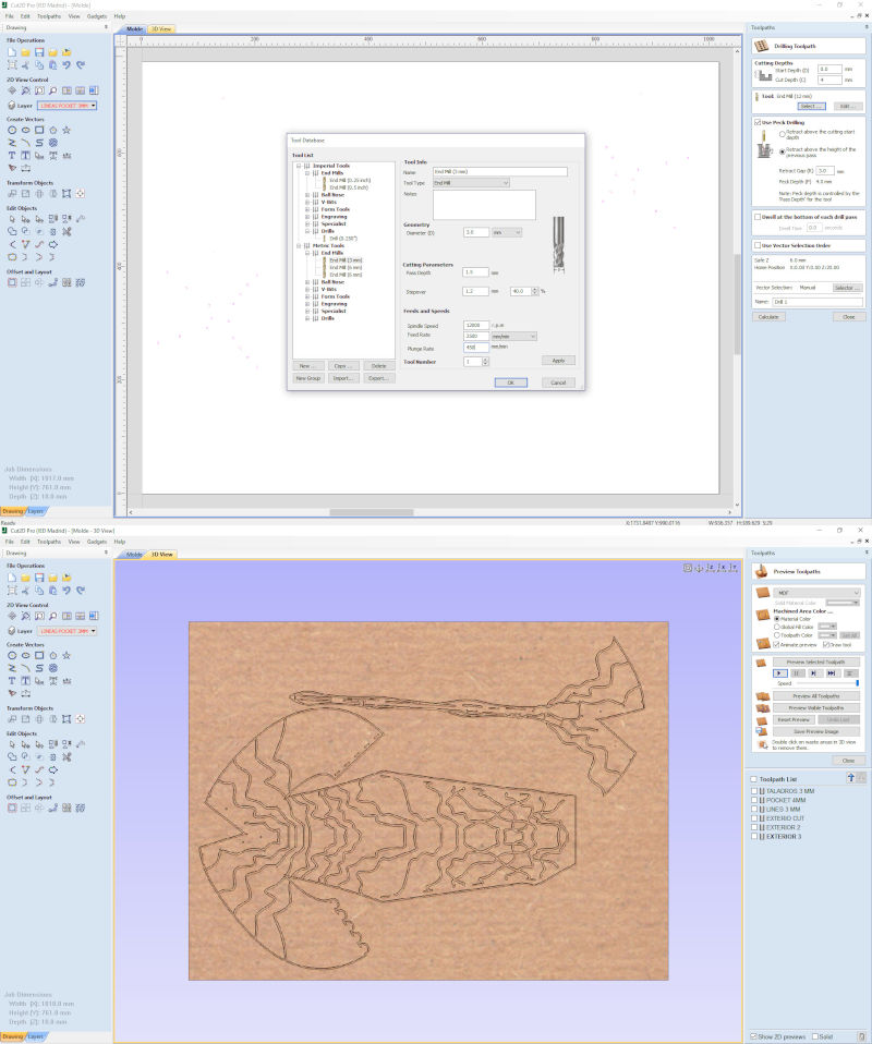
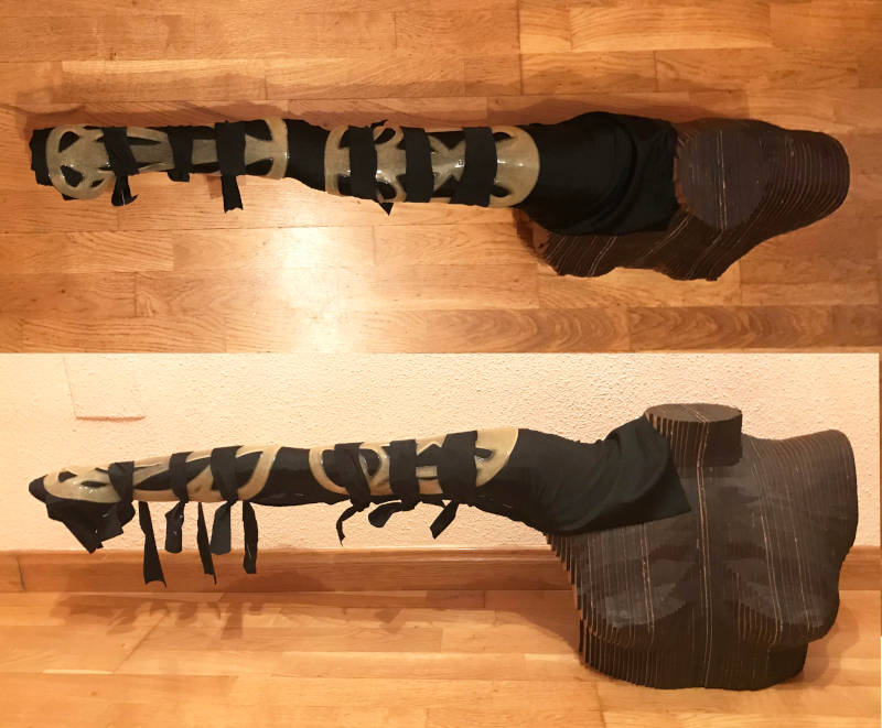
To cast the biomaterial sleeve and the system integration, I am going to mill a 10 mm foamed PVC board on the CNC machine.
To do it, I prepared the file in Rhinoceros and with Cut2D, following the necessary instructions and measurements that I developed during the Computer Controlled Machining week, I set the parameters needed to mill foamed PVC (Feed Rate: 2500mm / min and Plunge Rate: 450mm / min).
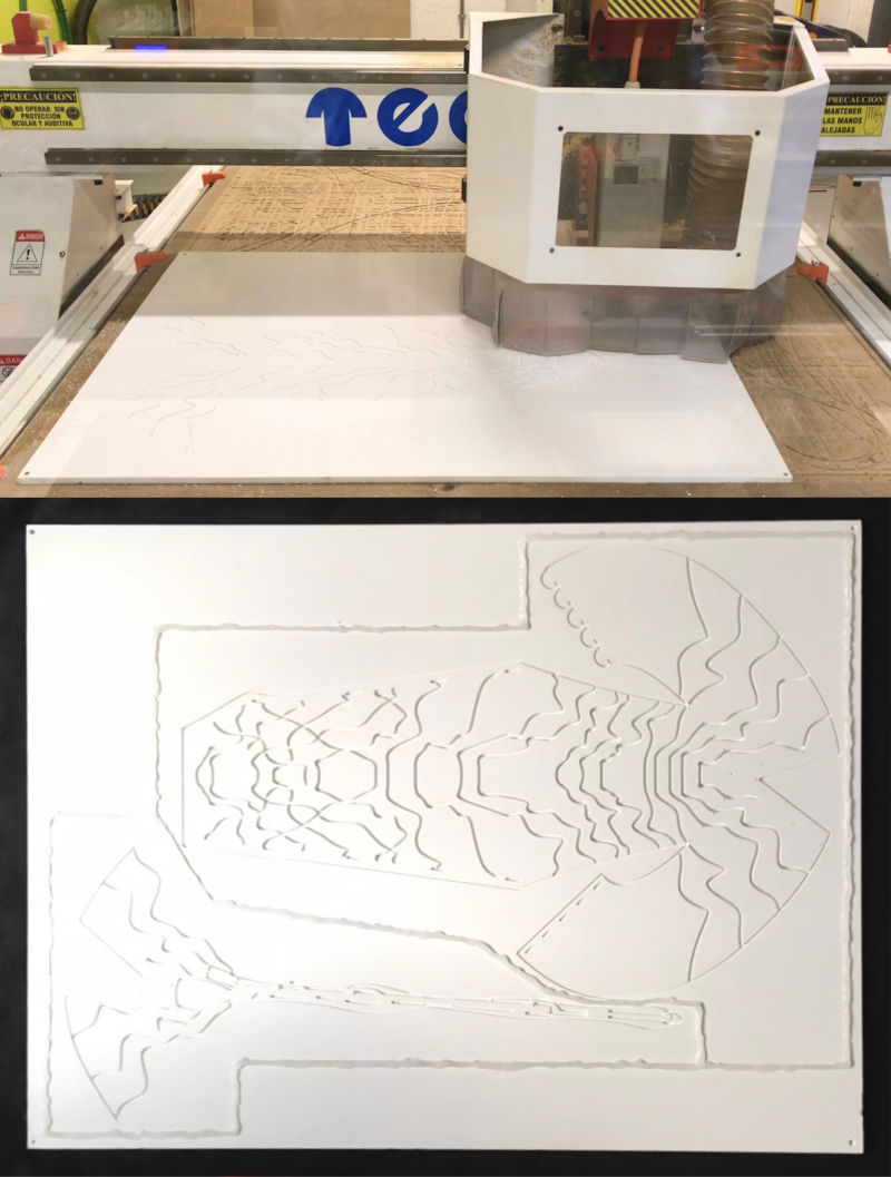
After half an hour of milling, this was the final result of the mold.
Since I had to do an alternative bioplastic cast at the last minutes 😅, I had to mill two Foamed PVC sheets, which both achieved good milling results.
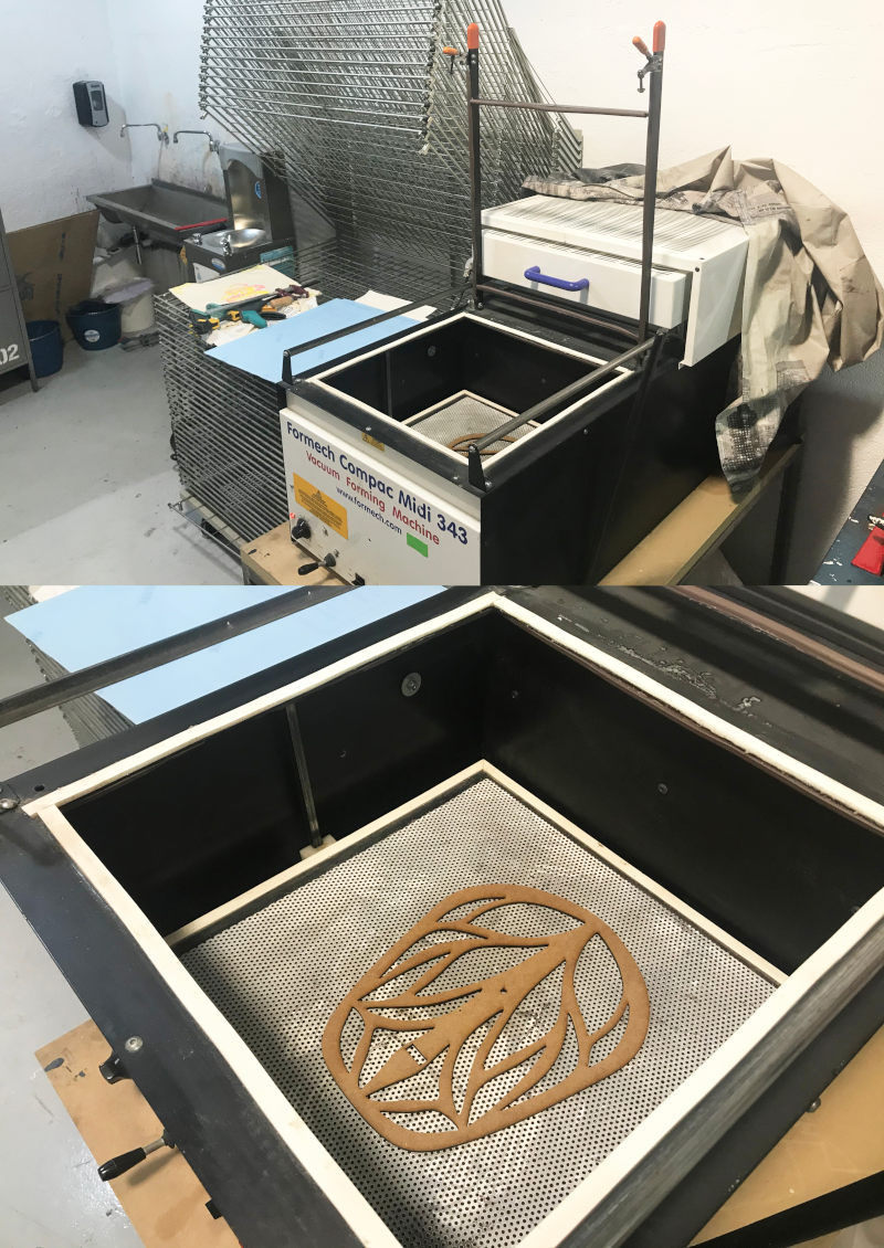
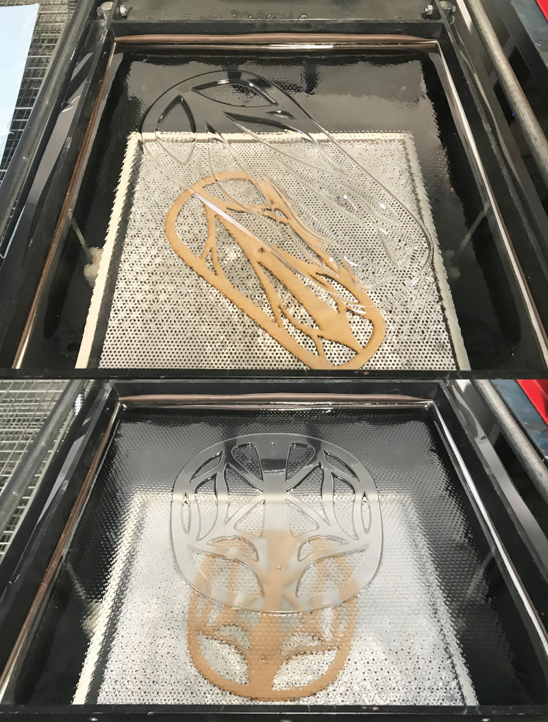
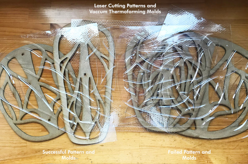
During Wildcard Week, I had the opportunity to test the plastic molds made with the Vaccum Thermoforming Machine for the brazers from the first prototype.
With the wood templates that I cut in the Laser Cut Machine, I made the molds where later I will cast the rigid or semi-rigid biomaterial.
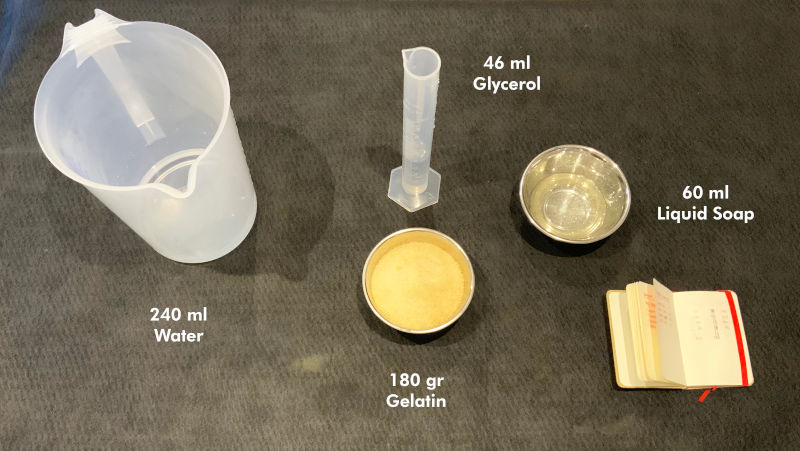
For the first prototypes of rigid or semi-rigid biomaterial, I turned to a bioresin recipe that I tested a year ago. For the preparation of the recipe I used this first ingredients measures:
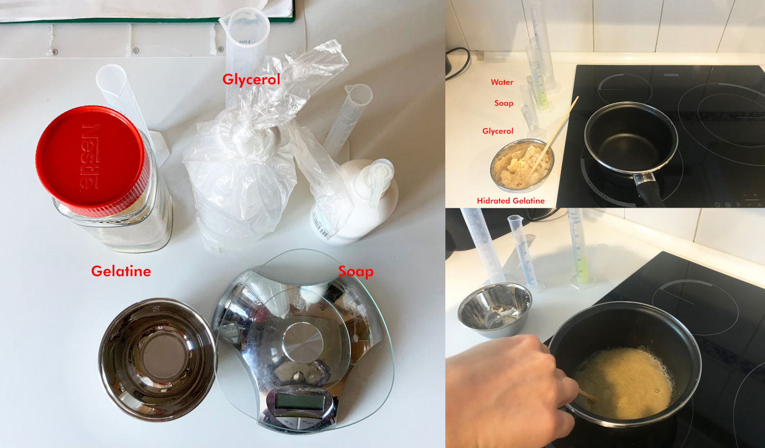
With the plastic thermoformed molds by the templates of the brazers, I am going to make the semi-rigid bioresin casts made with gelatin and liquid soap.
For this recipe, I readjust the ingredient measurements to the following:
Semi-rigid Bioresin
180 gr of Gelatin
60 ml of Liquid Soap
46 ml of Glycerol
240 ml of Water
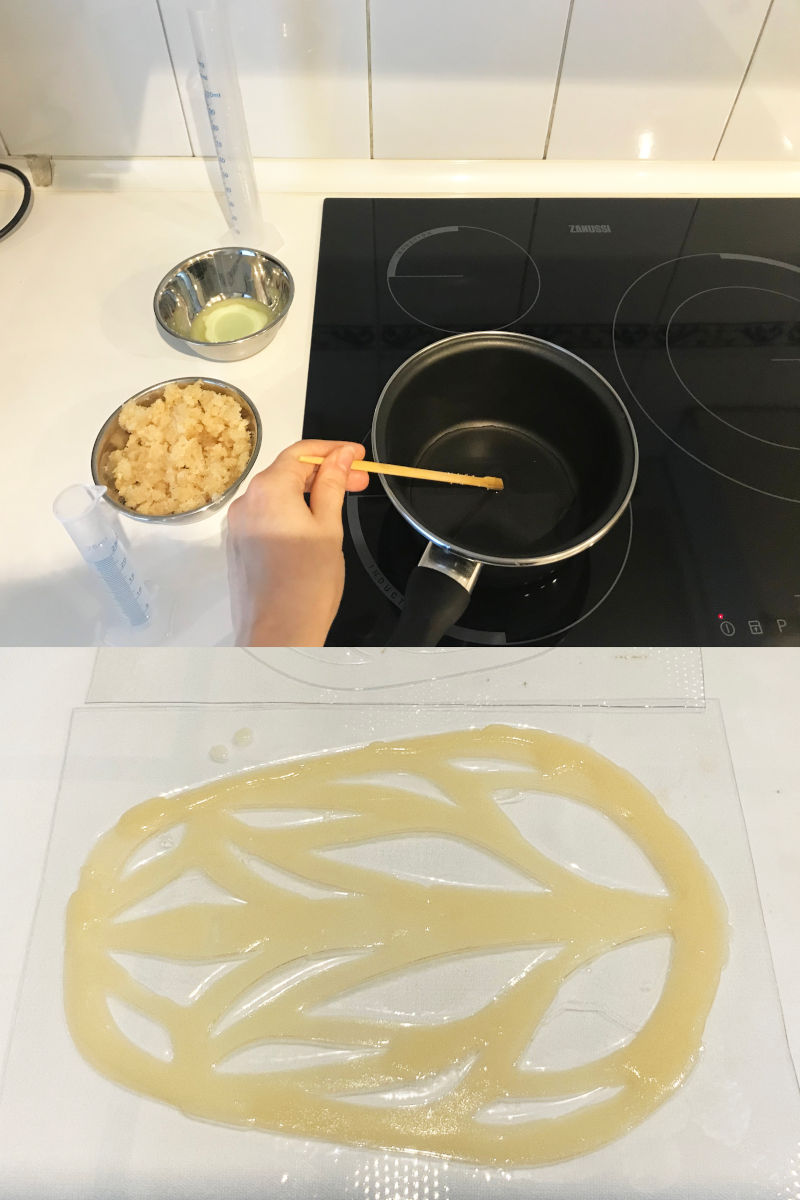
To cook these bioresins recipe, the following criteria must be this:
Step 1. (Before starting to cook) In cold, mix half the water with the granulated gelatin. This step is important to hydrate the gelatin and it does not form lumps when we cook it.
Step 2. We put the saucepan over medium heat and let the other half of water heat until it is at about 80 degrees. (If you don't have a kitchen thermometer, when you see the water start to get hot, without boiling, that's fine).
Step 3. When the water is hot, we lower the heat a little and add the glycerin. At the moment we add the glycerin, we begin to stir the mixture with the rod or wooden utensil that you use to remove. (From here it is important not to stop stirring until we finish cooking it, because the mixture can burn).
Step 4. Add the hydrated gelatin to the saucepan, and stir the mixture well until we don't see a lump and it begins to thicken.
Step 5. Add the liquid soap to the mixture and keep stirring. Stir all the mixture until you notice it begins to thicken, then it would be ready! 😍
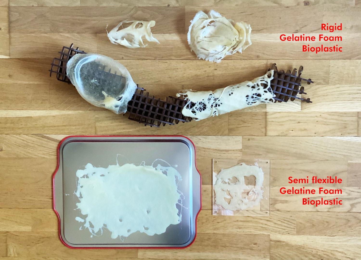
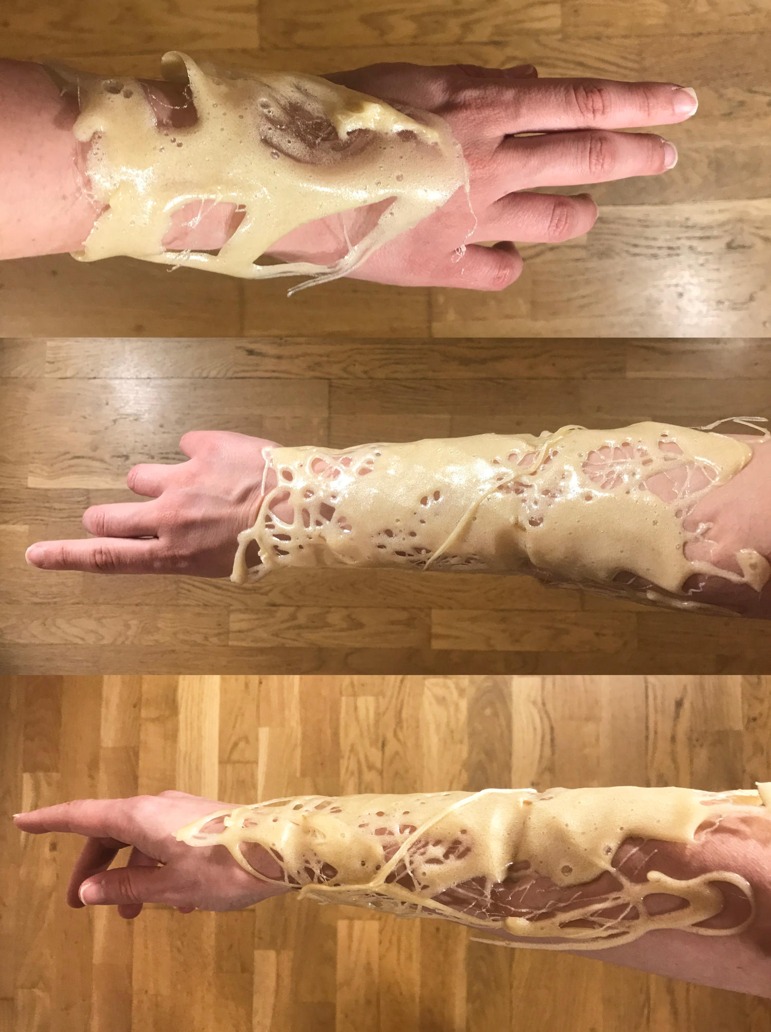
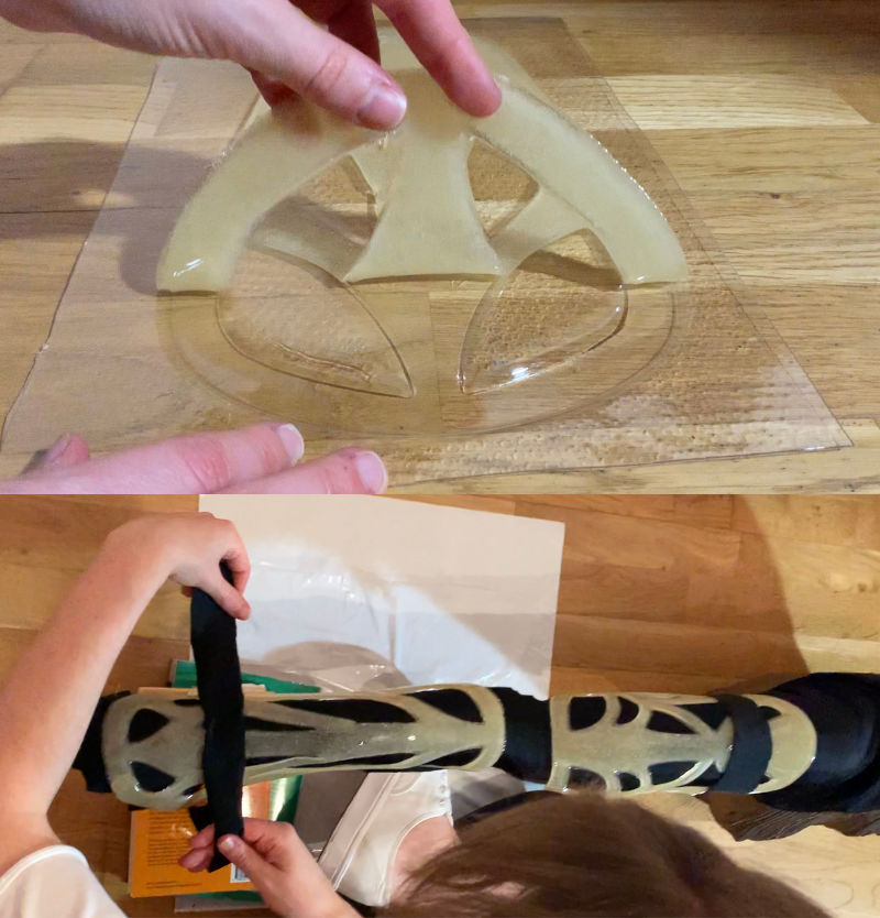
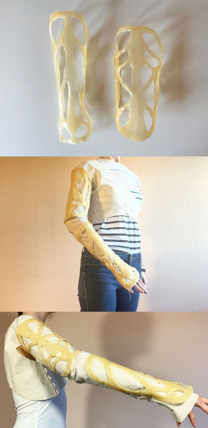
After 4 hours of mixture solidification , I unmolded the biomaterial and place the sheets around the arm of the mannequin.
The goal is to finish hardening and drying the brazers in the shape of the lower and upper arm. So I put some strips of lycra around the brazers and the mannequin arm, and let them dry for the next two days.
After two days of drying, this is the final result of the brazers, and how they fit around the arm of the first prototype. 😊
During the Wildcard Week, I did some experimental tests with the leftover raisins that I don't usually eat from the mix of nuts 😅🤣, and the result was a very elastic and light biomaterial. So I decided to make the sleeve and the integration system of the second prototype with this type of biomaterial.
For this type of biomaterial that I am going to use, sometimes biomaterials with high proportions of sugars can produce a certain electrical conductivity. So, to neutralize the conductivity in the material, I am going to mix the biomaterial with mica powder, which is a very resistant mineral to electrical and heat conductivity .
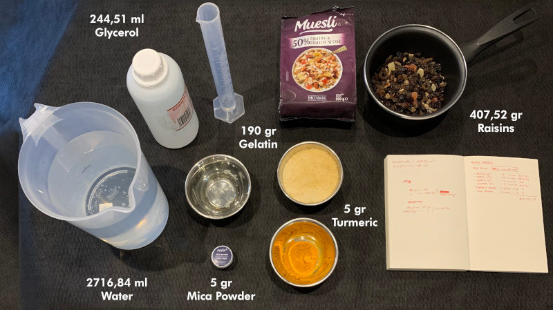
For this, I used the following materials:
Elastic Bioplastic (Raisins Bioplastic)
190 gr of Gelatin
407,52 gr of Raisins + 100 ml of Water
244,51 ml of Glycerol
2 ml of Water
5 gr Turmeric
5 gr Mica Powder
The first thing we have to do is process the raisins until we get a fine raisins cream which to make the biomaterial. To do this, we hydrate the raisins in water, and crush the mixture of raisins and water with a mixer.
When the mixture is more or less well crushed, I pass the mixture through a strainer to obtain a fine mixture of raisin paste.
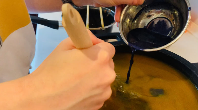
Here you can see a video, carrying out the crushing and casting process:
Step 1. (Before starting to cook) In cold, we have to do three separate mixes: first, mix half the water with the granulated gelatin; second, mix 50 ml of water with the turmeric; and third, mix 50 ml of water with the mica powder. This step is important to hydrate the gelatin, the turmeric and the mica powder and it does not form lumps when we cook it.
Step 2. We put the saucepan over medium heat and let the other half of water heat until it is at about 80 degrees. (If you don't have a kitchen thermometer, when you see the water start to get hot, without boiling, that's fine).
Step 3. When the water is hot, we lower the heat a little and add the glycerin. At the moment we add the glycerin, we begin to stir the mixture with the rod or wooden utensil that you use to remove. (From here it is important not to stop stirring until we finish cooking it, because the mixture can burn).
Step 4. Add the hydrated gelatin to the saucepan, and stir the mixture well until we don't see a lump and it begins to thicken.
Step 5. Add the raisins mix to the mixture, after the turmeric mixture and finally the mica mixture. Then, stir all until the mixture is homogeneous, and at the end it would be ready! 😍 😍
When the mixture is ready, I cast the biomaterial over the foamed PVC mold, and let it dry for several days. Here you can watch a video, carrying out the casting of the biomaterial:
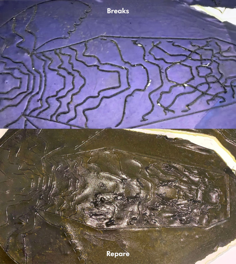
Unfortunately, the large-scale raisin biomaterial experiment had many complications:
On the one hand, I forgot to apply a release agent to the foamed PVC mold, and the sugar stuck strongly to the structural lines of the mold. So, when we tried to unmold it, it broke in several areas, and had to be repaired with bio-joints.
On the other hand, mixing on a large scale requires more drying time than the first pieces I experienced. I need a whole week to dry, and I needed to have the biomaterial before the trip to fab lab León.😓😓
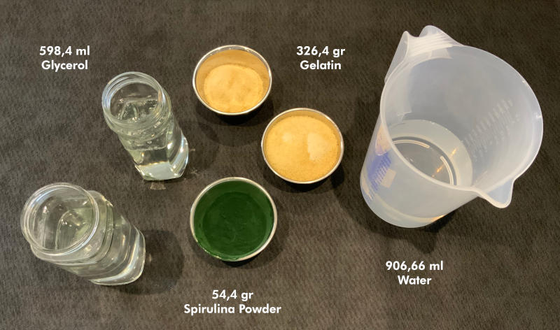
So, anticipating me to this catastrophe could happen, I decided to resort to the spirulina biomaterial with which I have worked on other occasions, effective and fast drying.
Step 1. (Before starting to cook) In cold, mix half the water with the granulated gelatin. This step is important to hydrate the gelatin and it does not form lumps when we cook it. In another separate bowl, mix the powdered spirulina with the water and reserve it for the end.
Step 2. We put the saucepan over medium heat and let the other half of water heat until it is at about 80 degrees. (If you don't have a kitchen thermometer, when you see the water start to get hot, without boiling, that's fine).
Step 3. When the water is hot, we lower the heat a little and add the glycerin. At the moment we add the glycerin, we begin to stir the mixture with the rod or wooden utensil that you use to remove. (From here it is important not to stop stirring until we finish cooking it, because the mixture can burn).
Step 4. Add the hydrated gelatin to the saucepan, and stir the mixture well until we don't see a lump and it begins to thicken.
Step 5. Add the spirulina mix to the mixture and stir all until the mixture is homogeneous, then it would be ready! 😍
Here you can watch a video in which I cast the biomaterial onto the the sleeve and the system integration mold. I love the effect of the spirulina microbubbles waves on the board. 🤩🤩
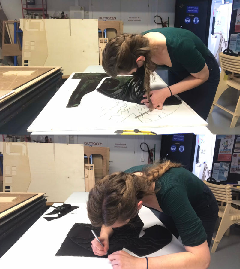
After three days of drying, and once I arrived at Fab Lab León, I proceeded to unmold and cut the biomaterial patterns, which came out with great ease!
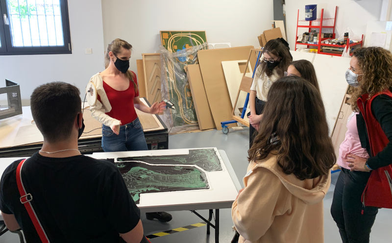
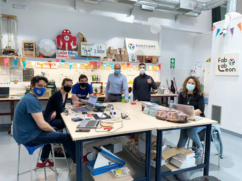
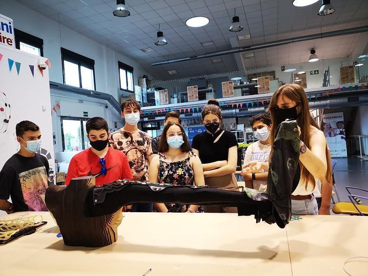
During my stay at Fab Lab León, I presented the progress of my final project to the Young Makers ("Jovenes Makers") of León, who were surprised to see the possibilities of creating biomaterials by themselves. It was a wonderful experience with them! 😍😍😍
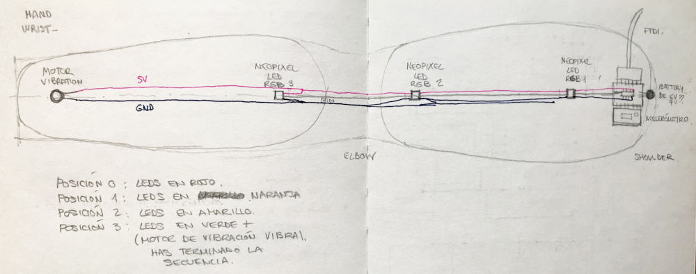
Regarding the part of electronic circuit, I had several doubts about how to arrange the components. The main idea of the electronics project consists to using an accelerometer to collect the data values when I am in different positions of the meditation exercises. With these data collected, program a color code for each position, which tells us if I am in the correct position or not. And finally, once I finish the entire sequence of exercises, incorporate a vibration motor in the hand, which informs me that I have finished and I have successfully performed my exercises.
To make this circuit, at first, I thought I should make an electronic board for each of the components that I was going to use (accelerometer + RGB LEDs + vibration motor), and communicate it through UART communication.
But talking to Adrian about the problem, he told me that it was not necessary to make so many boards, and I could make only one board using an ATtiny1614 microcontroller.
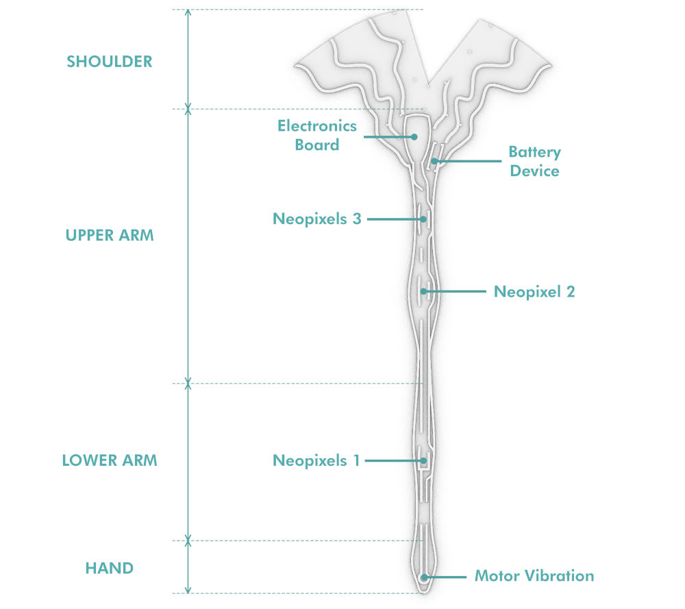
So, here, I thought about the best arrangement of the components and the PCB board around the arm, as well as the color codes that I could use in each position of the exercises. Finally, I decided to place the PCB board with the accelerometer ADXL 345 (Datasheet) on the upper arm. From there, their would lower a series of neopixels (Datasheet) along the arm, and I would end up with the vibration motor (Datasheet) in the upper palm of the hand.
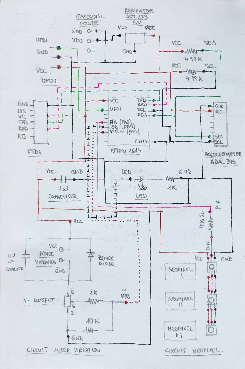
For the board design, as I do in previous assignments, I hand-draw the components and connections with colors to clarify my ideas before I start designing the board in Eagle.
The good thing about this board is, it is a remix between elements and circuits that I have already made during Inputs and Outputs week, so the design has been much easier than in previous weeks.
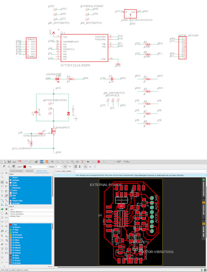
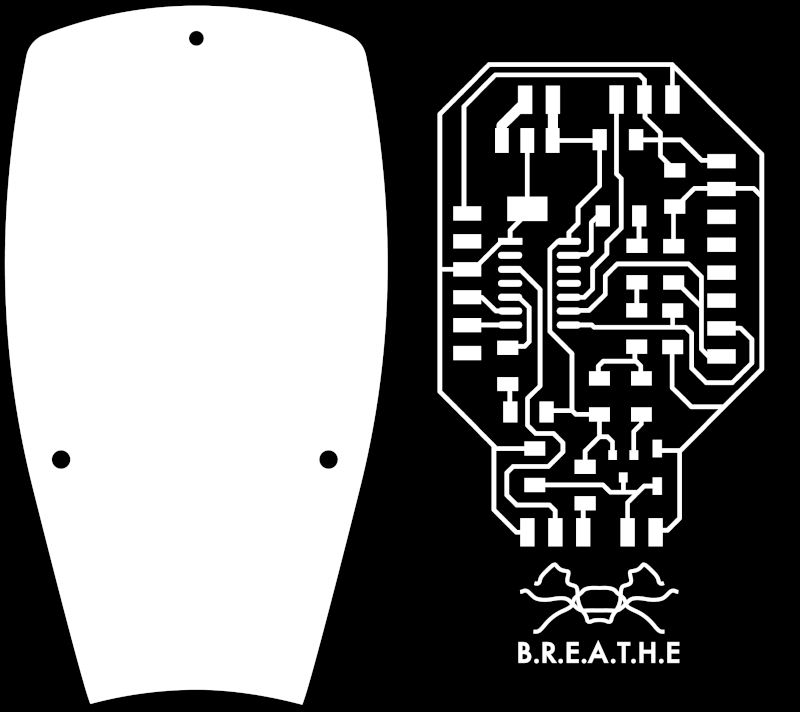
Once all the components have been designed and arranged, this is the final result of the borad that I am going to mill.
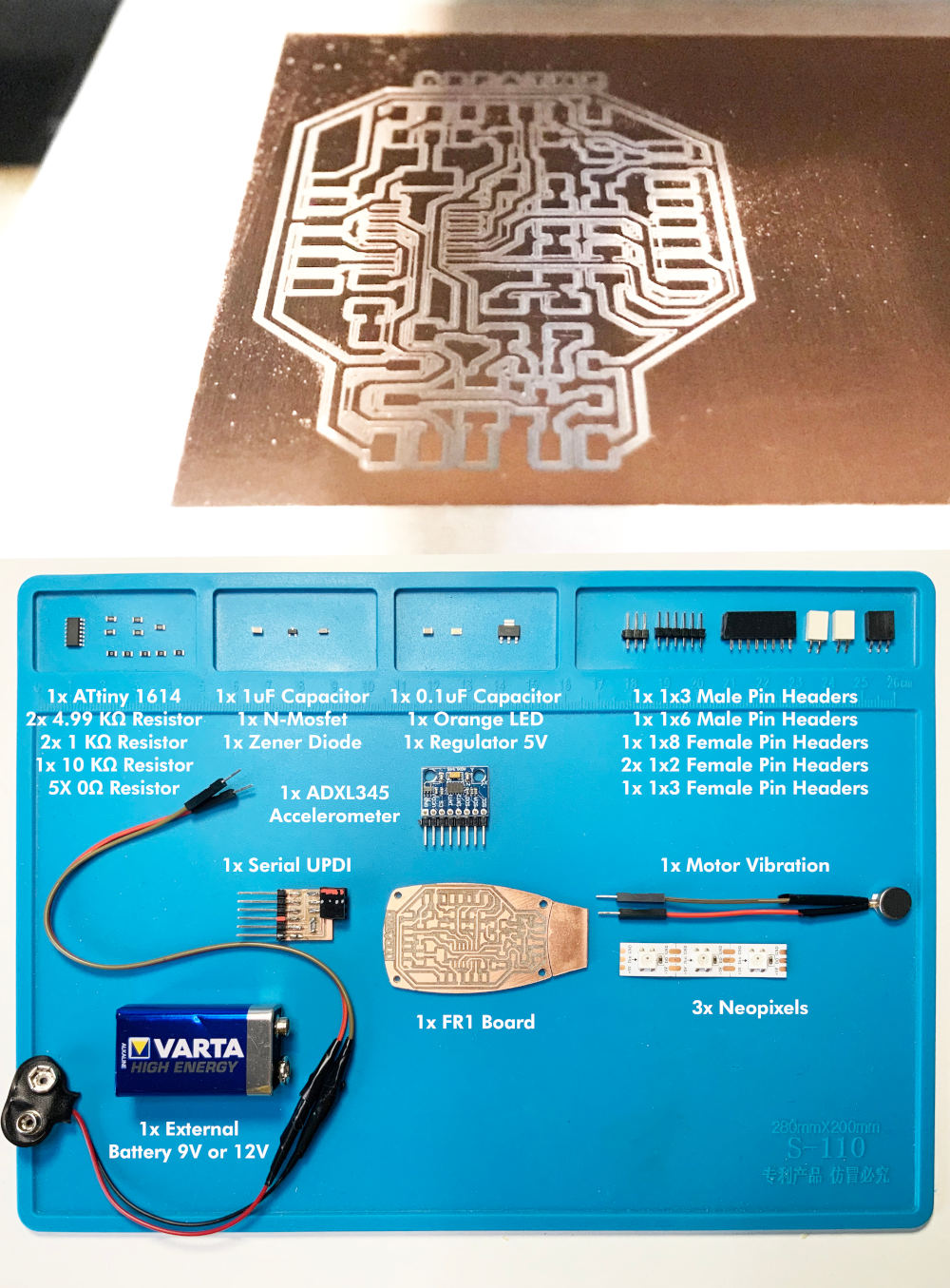
After milling and cleaning the board well with the soapy sponge, I am going to weld the following components:
1x ATtiny1614
2x 4.99KΩ resistors
2x 1KΩ resistors
1x 10kΩ resistors
5x 0Ω resistors
1x 1uF Capacitor
1x N-Mosfet 5.7 A 30 V SOT-23
1x Zener Diode
1x 0.1uF Capacitor
1x orange LEDs
1x Regulator 5V
1x 1x3 male pin header
1x 1x6 male pin header
1x 1x8 female pin header
2x 1x2 female pin header
1x 1x3 female pin header
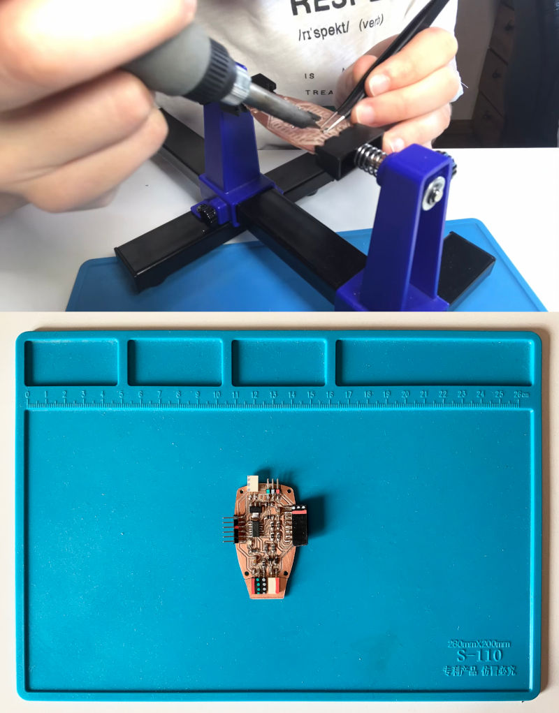
After an hour and a half soldering the components, this was the end result!
During the process, I had to make several electronic boards. On the one hand, the LEDs that I used initially were faulty, and on the other hand I suffered some mishaps with the regulators I was using and there were some shorts and deaths of some microcontrollers. Until the third board, I did not get the board work without any problem. 🙃🙃
About neopixels part I am going to locate on the arm, as their are strips of paper, I came up with the idea of making mini-boards in Illustrator and after milling in a PCB board for the three neopixels that I am going to use.
In this way, their are better attached, and as the boards are named, in case I have to replace any LED it is easy to stick and take off and knows its location. 🤗🤗
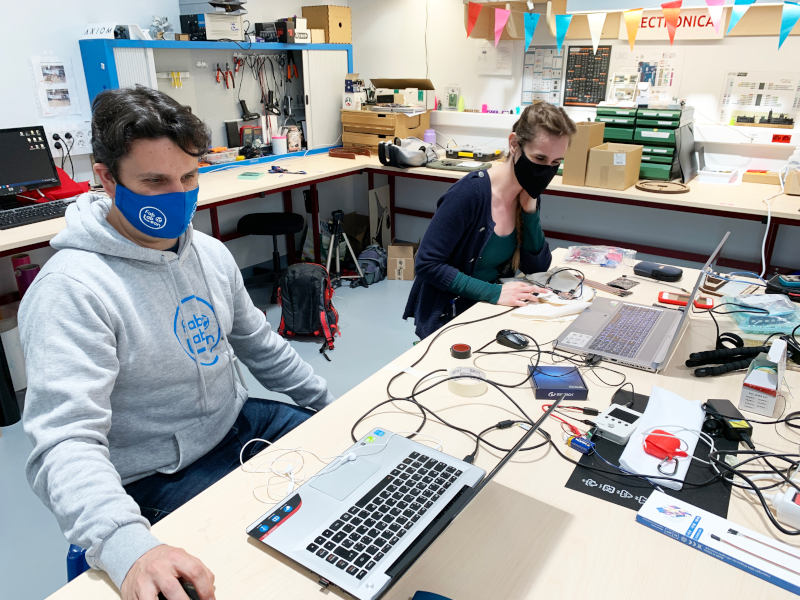
A week before my final presentation, I went to León 💛 to meet with Adrián + Nuria + Pablo 💚💚💚 and my crewmate Sergio 💚 at Fab Lab León, to finalize the final details of my project. My other crewmate, Mauro 💚, joined us on Friday from Madrid to work together on our projects.
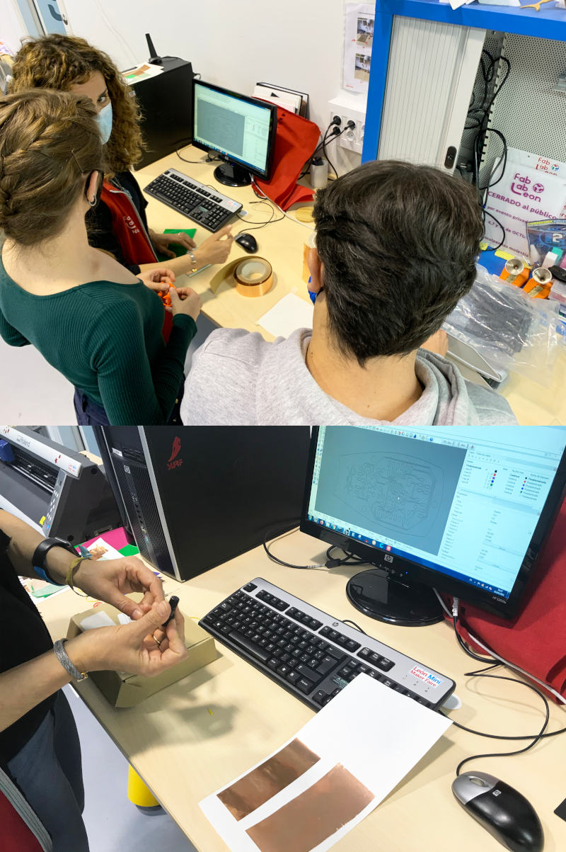
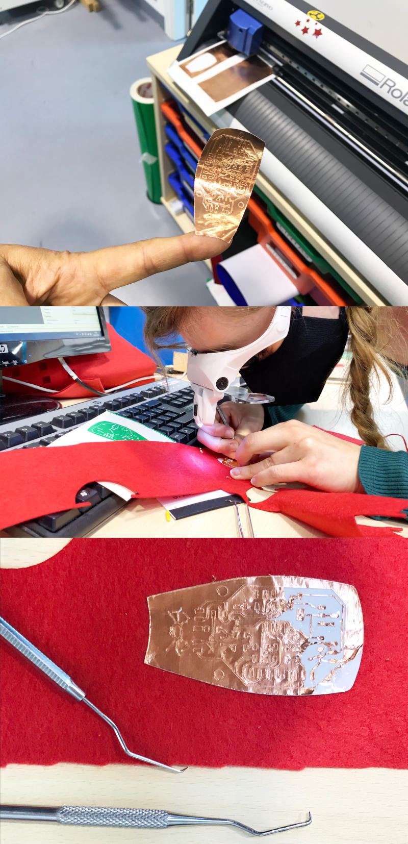
During the days at Fab Lab León, I tried to carry out with Nuria some tests of my electronic board with flexible copper, to check if it was viable or not for my project.
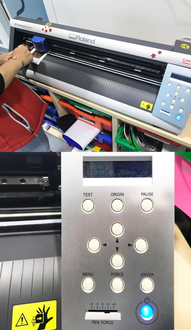
To do it, we used two types of flexible copper that Nuria had in the lab (one more rigid and expensive, and another more flexible and cheaper). For the flexible boards, Nuria explained to me how to use the vinyl plotter with a 60 degree blade.
To begin, we tried to glue the copper sheets on the epoxy first, and then without it, to see which was the best result.
After we place the blade and calibrate one of the sheets in the Roland GX-24 vinyl plotter, we must modify the speeds and thickness of the sheet in:
For the programming of the final project, as I have already explained in the Electronics Design section, the target is from the values that the accelerometer reads in each position, program a color code for each movement and end the sequence with vibrations.
Once the components are soldered, the first thing I do is load different codes separately, to check the operation of the accelerometer, the neopixels and the vibration motor.
For the accelerometer and the vibration motor, I have used the codes used during the Inputs and Outputs Devices weeks. But for the neopixels, I have used the programming code that Adrián made for outputs with neopixels in Adrianino 😍😍.
Here you can watch two videos, checking the operation of the project's outputs.
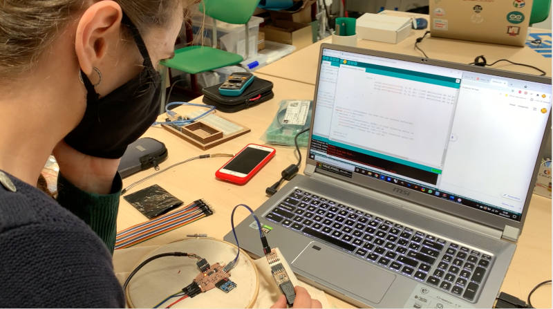
At fab lab León, I started doing all the programming part of the circuit, and I couldn't have done it without the help of my right hand and Jedi master Pablo! 💚💚
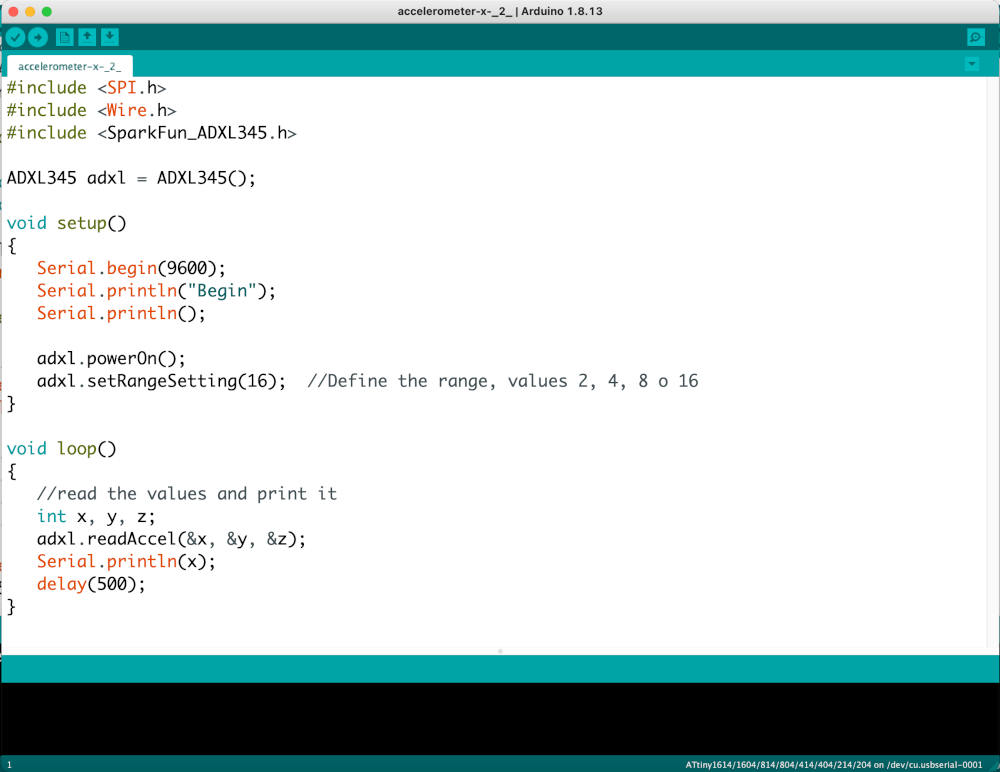
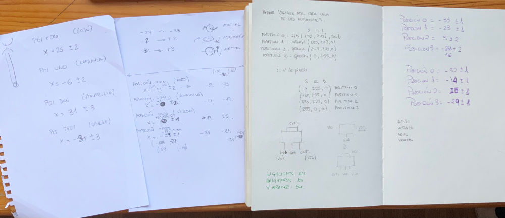
First of all, using a basic code to read data with the ADXL 345 accelerometer that I am going to use, we are going to start reading values in a single axis, as Neil recommended me to do during the Applications and Implications review (51:45 min).
Here you can watch a video, where depending on the position of my arms, a range of optimal values appear to start working with the accelerometer and the neopixels.
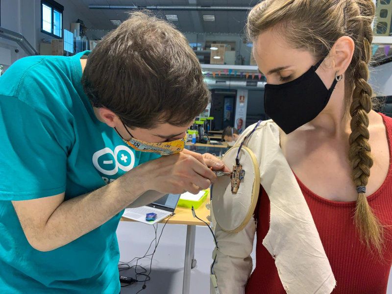
During the process we had several accelerometer readings, each one more different than the last 😳😳. Nuria told us that this could be because the accelerometer inside the toile is in constant motion due to the fluidity of the fabric. So to program it, she advised me to use an embroidery hoop, to keep the accelerometer still on the sleeve, and to get more accurate values.
For the programming of neopixel leds with the accelerometer, Adrián + Nuria + Pablo, they helped me a lot during the process of placing and physical programming of the board. In this picture, Adrián was helping me remove a pin from the board that it was starting to short the board 😘. I do not know what I would be without them! 😍😍😍😘😘😘
For the new code, what we do is program each of the values- positions of the arm, a different color code. Initially the color code was Red > Orange > Yellow > Green, but seeing that warm colors were difficult to recognize with the sleeve, I decided to change the color code to:
Position 0 (Idle): Red (255, 0, 0)
Position 1: Magenta (255, 0, 255)
Position 2: Green (0, 0, 255)
Position 3 (Final): Blue (0,0,255)
After several tests and calibrations, here you can watch a video where I do the entire sequence of movements with the initial color code.
Finally I proceeded to incorporate the vibration motor into the accelerometer + neopixels sequence.
In the final part of the code I added programming parts that I used during Outputs devices week, and I located them in the last position of the exercises.
Here you can watch a video, where I am testing the vibration motor when it is in the blue position.
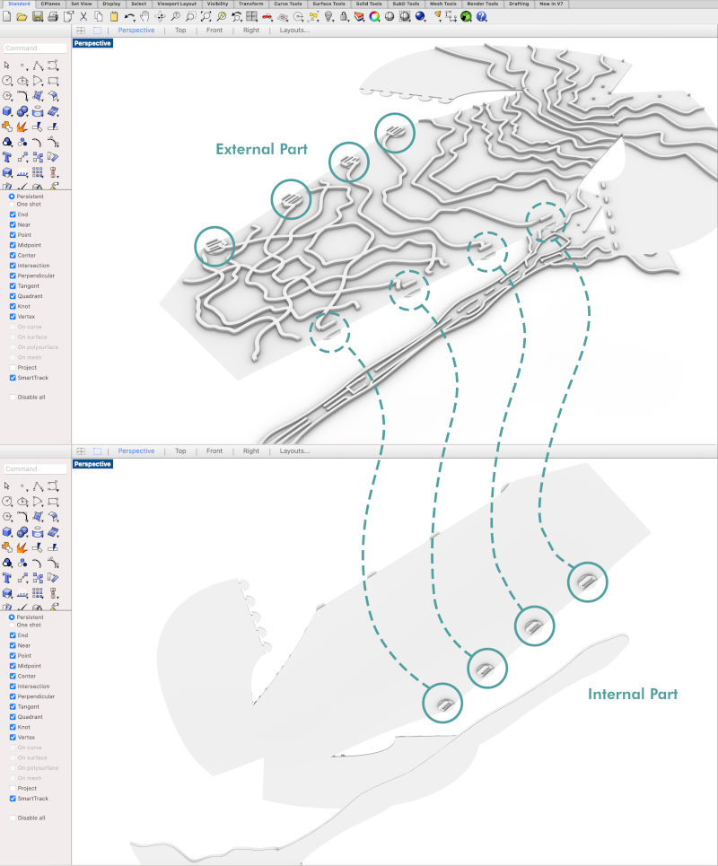
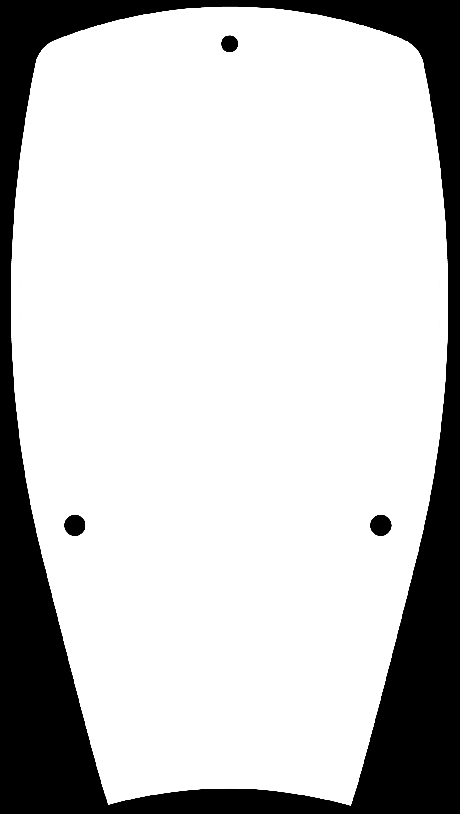
To do it, I have drawn the contours of the boards, the 12 V battery holder, the neopixel boards, the vibration motor and the rails where the circuit cables will be integrated.
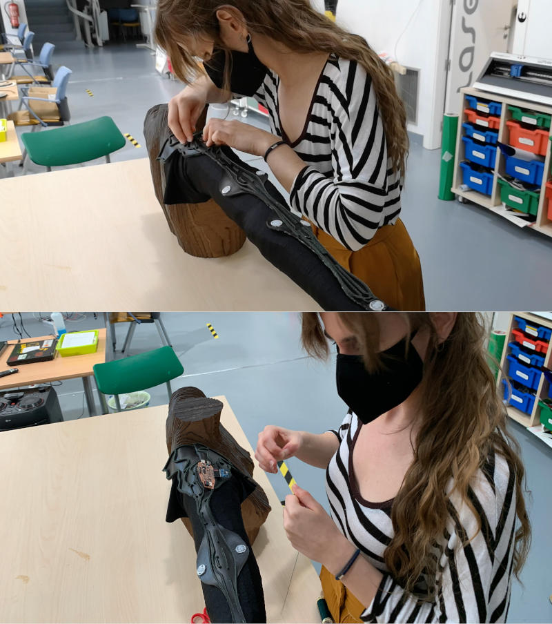
In these photos, Pablo and Adrián took pictures of the sewing processes of the brackets in the system integration. 😍
Once the brackets were sewn, I replaced the bioresin brazers from the mannequin to put the system integration and work more comfortably with the circuit on the arm.
The first thing I do is adjust the main board and I sew it on the biomaterial throught the holes I made in the PCB board.
For the main board, initially I was going to use the accelerometer that I bought and soldered, but since the board was slightly flying, Adrián gave me his accelerometer that he used in Adrianino, which is more compact and fits the arm better. 😘😘
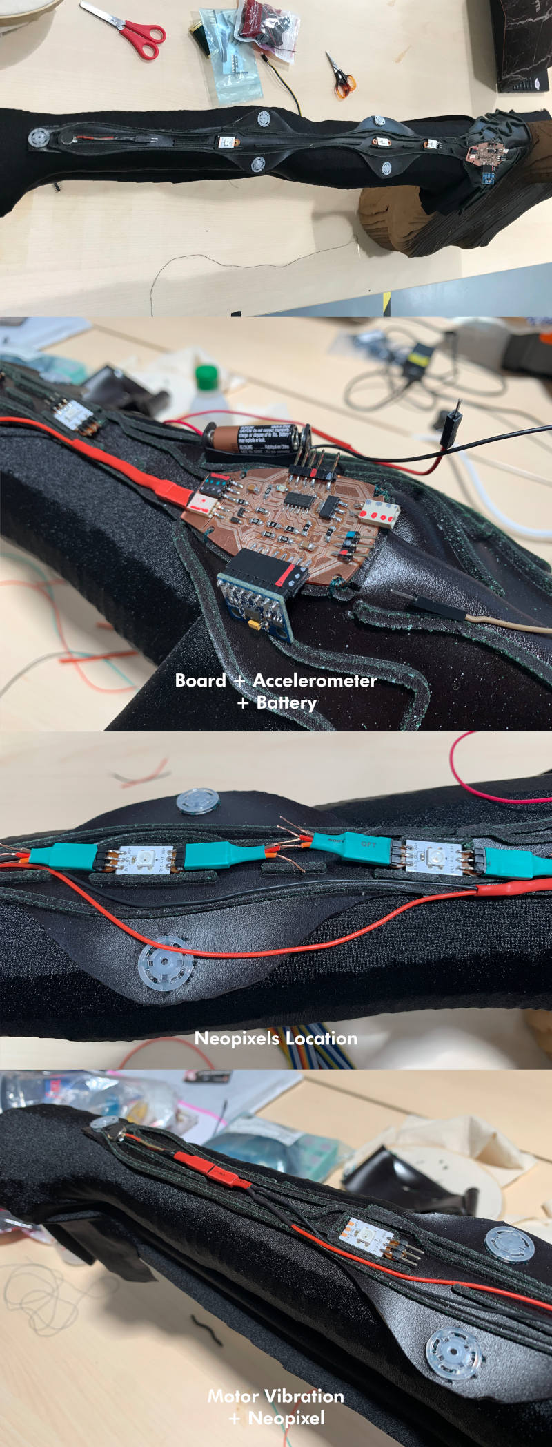
After sewing the board, I attached and sewed the battery holder. and next thing was the neopixels boards. To make the cables easy to remove in case we had to replace any component, I used some dupont pins I soldered with some silicone cables that Nuria lent me and their are very flexible and suitable for my project. 😍😘
Finally, as with the neopixels, I wired the vibration motor with the same removable cable system of Dupont pins + extension with silicone cable.
Here you can watch a video where I measure and place how the integration of the circuit will be inside the "spine".
And this is the final result once we have sewn and integrated all the cables.
In this video you can see how I join the part of the integration system with the biomaterial sleeve using the hidden brackets. 😉😉
A few hours after my final presentation, I showed to the Young makers ("Jovenes Makers") of León, the final result of the project and the built-in of the system integration. Many of them were amazed at the change my project had made from one week to the next, and I hope that some of them will be encouraged to try and test their own biomaterials. I hope to see again Jovenes Makers soon, as well as return to fab lab León with Adrián + Nuria + Pablo 💚💚💚, who more than instructors have been a second family for me . I love you and I miss you guys. 💖💖💖
About Applications and Implications, in this link you can access to this week's assignment. There, I explain in detail which are the applications of my project, as well as a previous list of materials and work that I must and have done during this project development.
Since all the development of this project is going to be public, I want to use a Creative Commons (CC) license, which is a non-profit organization focused on getting the largest number of creative works available so that others can reproduce and share them legally. This organization offers you several licenses according to the copyright, commercial use, communication or public assignment we want to carry out.
You are free to: share (copy and redistribute the material in any medium or format) and adapt (remix, transform, and build upon the material).
Under this following terms:
_Attribution: You must give appropriate credit, provide a link to the license, and indicate if changes were made. You may do so in any reasonable manner, but not in any way that suggests the licensor endorses you or your use.
_NonCommercial: you may not use the material for commercial purposes.
_ShareAlike: if you remix, transform, or build upon the material, you must distribute your contributions under the same license as the original.
Also, during this week assignnment I designed a slide and a previous video of the project:
After integrating the entire circuit into the spine, the first thing I do is recalibrate the accelerometer and readjust the accelerometer values in the final code to achieve the final sequence of colors.
This is a video performing the sequence, only with the spine:
Finally, with the help of my sister, we incorporated the entire sleeve and the integrated system. This is the first video testing the sequence of movements: 😍😍😍
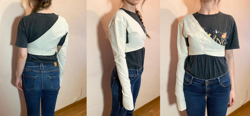
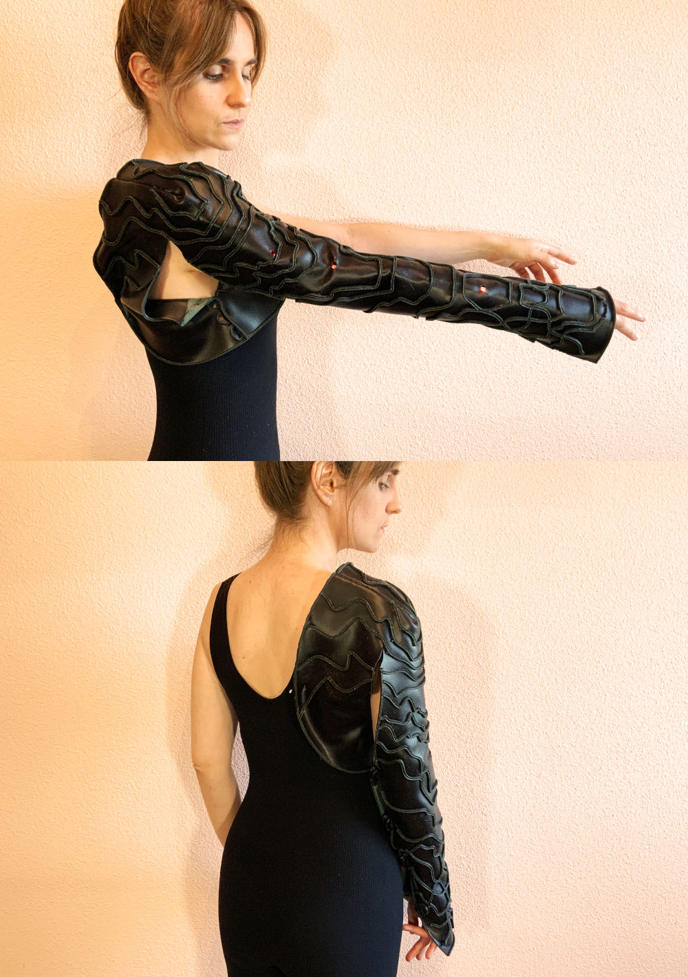
And here, you have some photos showing the final result of the project. 💚💚💚
