Electronics production
For this week we had to produce a PCB, program it and test it. I plan to mill a FTDI-UPDI programmer

- Linked to the group assignment
- Documented how you made (mill, stuff, solder) the board
- Explained any problems and how you fixed them
- Included a ‘heroshot’ of your board
## Setup
### Assembling the machine
To mill my PCB I use our newest low budget milling machine from Sainsmart.
I began by putting the parts of the machine together… The machine is pretty straightforward, it is composed of 3 axes without any endstops. It has stepper motors on each axis and a DC motor as a spindle.

It took me almost 1 hour to assemble everything. I quickly checked if everything work correctly by powering the main board. You can control the machine using a tiny controller (at your own risk) or with a computer.

After reading the manual I move the 3 axis and observed a strange behavior… The X axis was inverted…
 This may happen when a machine firmware isn’t well configured, but this machine was shipped with the firmware already uploaded in the board. As every board from this vendor should receive the same firmware, the problem comes from elsewhere…
Another way to fix that is to switch the stepper phase. After swapping the black wire and the red one as well as the red wire and the black one. I plugged back the connector and the X axis move in the correct direction !

I then use my computer to control the machine using Candle, a GRBL controller. Candle is very convenient. I tried to “air” mill several demonstrating program successfully.
I decided to use V bit suplied with the machine to begin carving. Since they are pretty cheap, I’m more comfortable breaking one of these than the straight ones…

Mounting the V-bit

I use the two supplied wrench to lose the tool handler and insert the end mil. Then I tighten everything back and the bit seems to be fixed in place. I started the spindle and except the heavy vibration everything was OK. I think the vibration are mainly due to the bad quality of the rotor. A better setup will be to use a belt between the motor and an additional shaft mounted on bearing. This could avoid the motor to handle radial force while reducing vibration. However, it may add cost to the machine. I’ll definitely change that one day.

Thus, the tool seems to turn perfectly round.
To mill the first test we will be using a sacrificial layer on which we will stick the desired blank PCB
PCB setup
I used double-sided duct tape to set the plate in place.

This machine as no end switch to automatically set the zero position. It has to be set manually. To set the zero coordinate, you can use Candle software to move to the desired position and press XY zero the set the zero. To set the Z zero, the process is a bit more complex. When I was in internship at the Waag Amsterdam, Henk explained the zeroing method on the Rolland milling machine. He was moving the bit just above the copper plate manually and then loosen the bit to let it fall gently on the copper. This technique was very useful. But on this machine this is impossible because the bit move upward when you tighten it…

I tried instead using a piece of paper and manually approached the bit to the sheet of paper until I cannot move the paper anymore. This was a good technique, but I figure that the paper was 0.1mm thick so I was 0.1mm above the plate. Moving downward by 0.1mm solve the major issue :)
I tried to mill the USB-UPDI program from another student and got this result :

Obviously the plate wasn’t horizontal and need to be leveled. We leveled the plate manually using a tiny piece of paper to raise by 0.4mm on the other side of the plate.
I tried to adjust the height of the PCB manually. But after a bunch of tests, this trick seems very time consuming… So I looked for another solution. Sainsmart sell a Z probe sensor for 10$… I cannot wait for the shipping to deliver me this sensor. So I went through make my own.
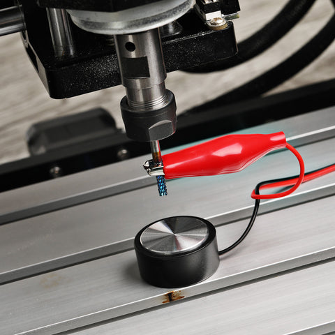
The sensor should be wired on AD05 input on the motherboard. For what I understand, this is just a set of two electrodes. When current flows from one to another, the signal should pass through the AD05 input and be interpreted as a touch down.
I make my own cable using alligator clip and two cable. I used a JST 3 x 2.54mm as a connector to the board.

After wiring everything, I connected the GND clip (black) to the endmill and the positive clip (red) to the PCB while making sure there is connection between the copper and the clip.

Using the candle software, I tried the Z0 button… And the bit detect directly the 0 in midair… I checked all the connection and tried again, same result. The board is always detecting zero…
I thought the motherboard used an internal pull-up resistor. But if not, it shouldn’t detect at all ??? So why the board is detecting always the contact… Making the clip touch all others change nothing…
Maybe the board try to calibrate some threshold… So I decided to add a pull-up resistor to lower the electronic noise and ensure there is a big difference between open and close state.
I choose a 4.7k Ohm resistor from hazardous calculation. Then I added it to the positive cable. And bam ! It works like a charm !
Now the machine can probe the Z axis like a boss !

I modified the probing script in candle settings to probe the milling area before a job. Here is my code :
G91
G21
G38 .2 Z-50 F100
G92 Z14.09
G0 Z5
M30
Milling
To really understand the limits of the machine, I tried to mill a test file I found online. I opened this file I used two different approach to do so. I used FabModules and FlatCAM to mill PCB. Here is how I did.
FabModules
Fabmodules is an online tool made by MIT CBA with Fablab network. Also called “Mods” this tools was made to control whatever machine you want in a fablab. You can install it locally or use it online as the local version is mostly a web server hosting the website available here

After opening the right program, you should be able to import and image. You can choose between PNG and SVG. Usually I used SVG but the test I’ll mill now is accessible here as a PNG.

I used the default value of mods for speed and feeds. But I had to deal with the mill diameter. I used two different bits during tests. One of them is a V-bit which mean its diameter depends on the depth of cut. The copper layer seems to be less than 0.1 mm -> 0.004 inch. Thus, I used 0.004 cut depth in mods. At 0.2 mm of depth, the mill cut diameter is approximately 0.4 mm So I used 0.016 inch as tools diameter
For the outline, I plan to use the same bit but as it will go deeper, the diameter change once again. The PCB is 1.4mm thick. So I need to go 0.05 inch deep. But as it may be difficult to cut all the way through at once, I’ll do multiple pass by 0.01 inch each (4 pass). At 1.5mm deep my mill diameter will be 1 mm which is equal to 0.04 inch
Here is all my settings :

After all this calculation, I finally click on “Mill traces” to generate the toolpath which is automatically downloaded. I did the same with “Mill outline”. I duct taped the PCB on the bed, connect to the machine using an USB cable and started the Candle software. Then I opened the generated file and run the program. The milling start by probing the pcb and then, the machine started to mill the PCB. The result were better than ever !
Here is what I got :

Engraving the traces is OK with V mill but cutting through the plate is difficult. Obviously there is an issue with the outline. My linetest is cropped… My best theory is that I didn’t select the right program because I remember clicking on the “Mill outline” button before I do the math… I didn’t had the problem after that… The usniverse is laughing at me !

After this “success” I tried to mill the USB - UPDI programmer, I used a V mill to cut the traces and then a V mill to cut through the material (using this time the right mill diameter) I measure the V mill diameter once again to set the cutting diameter on Mods.

This time, the mill wasn’t tightened enough and went down during the process… As a result, the mill went too deep and all the traces aren’t ok. As I didn’t notice, I thought the problems came from mods… I got angry toward it and switch to another software, FlatCAM. The flatcam part is available below.

I tried again later with the same program, this time with the bit tightened and got that result :

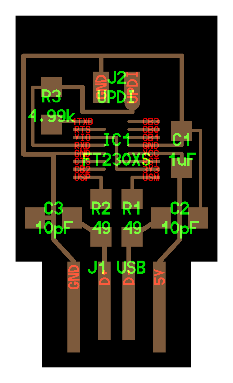
Even if this board came successfully out the second time, I was unable to solder it because the main FT232 chip was out of stock. So I decided to switch to the UPDI adapter instead.
So I tried to mill a FTDI - > UPDI programmer instead.
I use this hello.USB-UPDI.FT230X file :

I repeated the same process with the same settings and got this board :

I used a soldering station to tin every SMD pad and then solder the resistor and the pin header.
Here is the final result !

On week 9 I’m actually using this adapter to program my LED test board.

FlatCAM
I also tried FlatCAM along the process. FlatCAM is a great tool to prepare PCB milling. It can generate toolpath just as Mods do. I imported a calibration file to test out my machine and see what it is really capable of doing.
I started by cleaning the whole machine to be sure that the mechanics is OK. I washed it and apply lubricant on the different axis

You can download the test project by clicking on the button below :
Import the file and start to tune flatCAM.

I used the same settings as mods except for the V-bit calculation since FlatCAM as a V-bit calculator integrated. After checking the setting, I exported the toolpath using the NCC tools. I generated only the trace programm since this is a test. To cutout the circuit please use the cutout tools.
Save the CNC code and import it in Candle software. After that you’ll be able to mill the same way you did with mods.

I started the milling machine once again ang got this result :

As you may see, the bit was too deep because of the loose mill which went down a bit. Has I switched from Mods to FlatCAM I realised the problems didn’t comes from the software but from my setup. I finnaly removed the bit, replace it with a new one and tigthened everything back.
This time I started again the program and got that result :

As you can see, the trace are way better this time. But I notice a little deformation on the squares. So I decided to have a closer look at it.

Using my microscope I look at the small squares. And realised, the mill has a strange path. This is probably due to a bad mechanical link between the milling shaft and the motor. Or maybe it can because by some backlash in the Y axis.
Here is what I discover in the Y axis
