WEEK 7: COMPUTER CONTROLLED MACHINING
INDIVIDUAL ASSIGNMENT
(MAKE (DESIGN + MILL + ASSEMBLE) SOME THING BIG.
NEWS PAPER STAND
This week is full of challenges for me, as an Electrical Engineer. I am new for 3D Modeling and this week we are going to push our limits to next level in 3-D designing and modeling by making something big. So for this week's individual task our instructor gave me a task to make a NEWS PAPER STAND for library While searching designs on internet we saw one design whose dimensions aren't mention but, it was beautifully press fit by making boundaries (which I felt was missing in my news paper stand) with the description "No glue, fastners, nails or screws required". I decided to change its design and make it to cover this week's task.
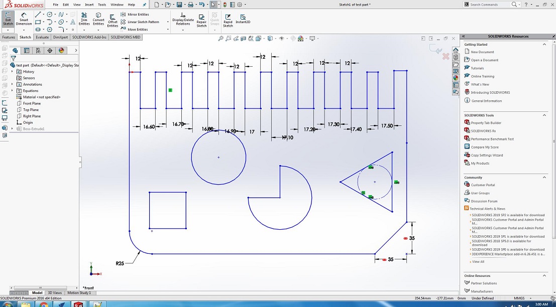
OPEN SOLID WORKS AND SELECT THE PLAN
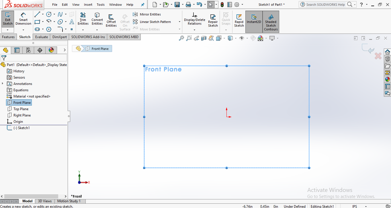
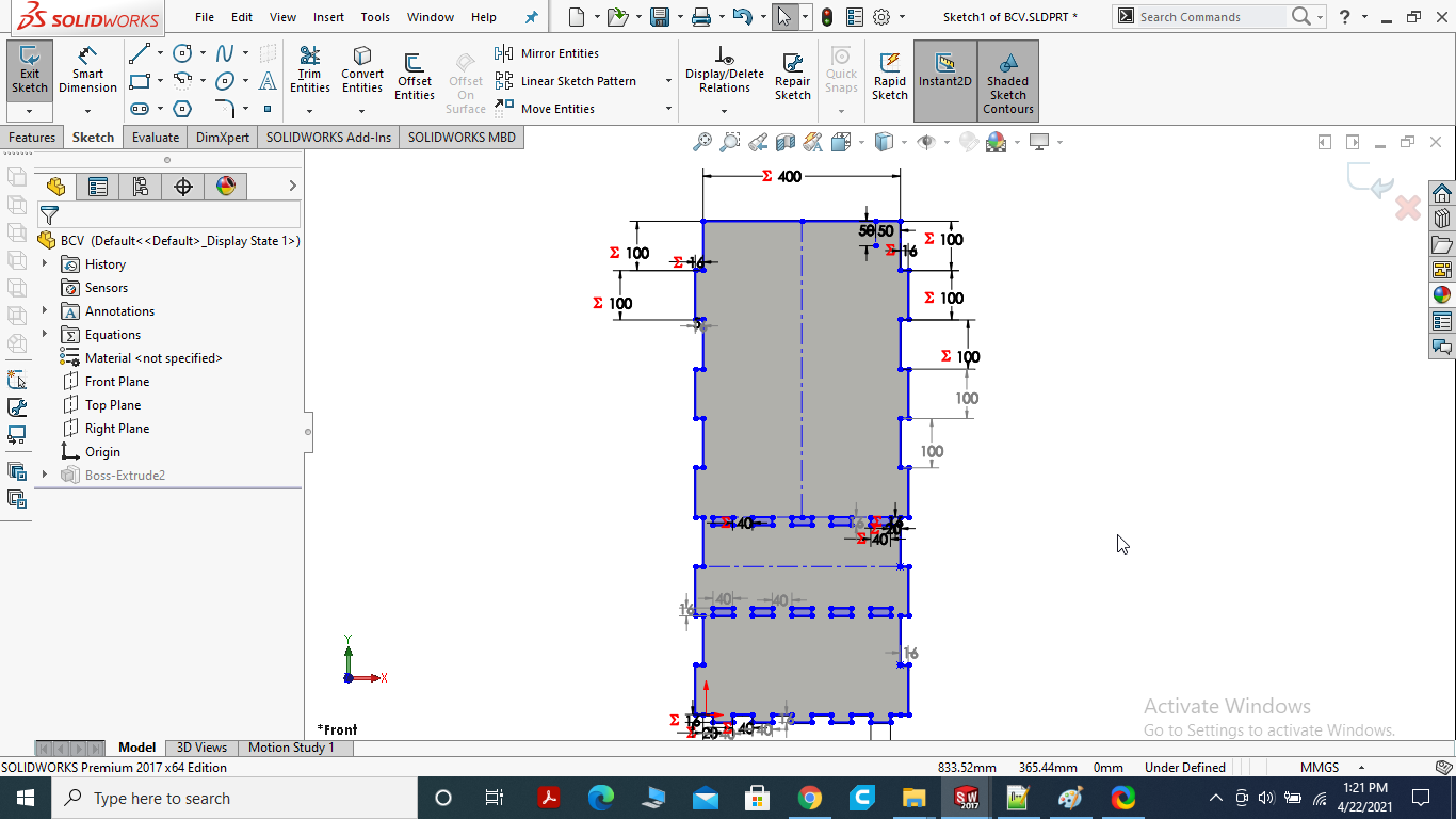
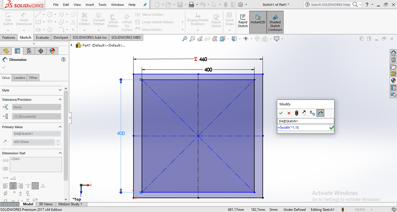
SKETCH THE FIRST PART OF NEWS PAPER STAND USING PARAMETRIC EQUATIONS
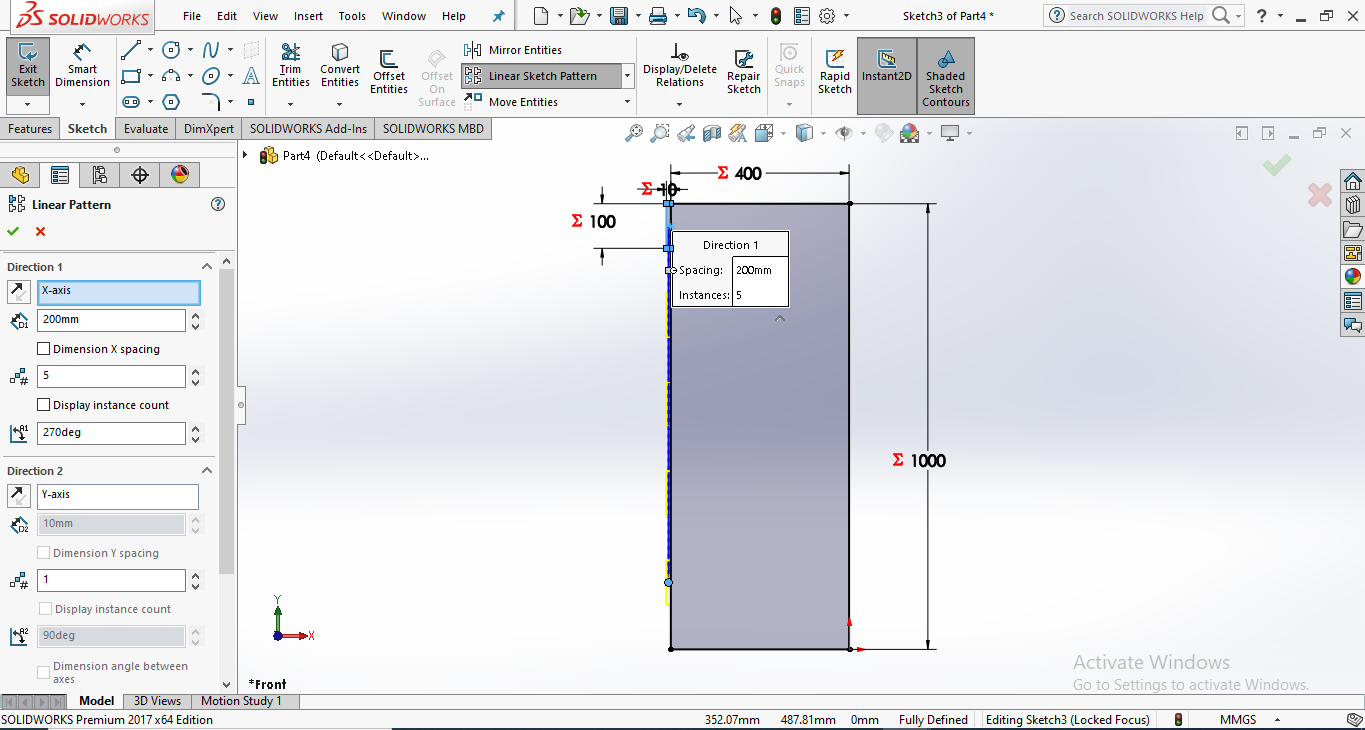
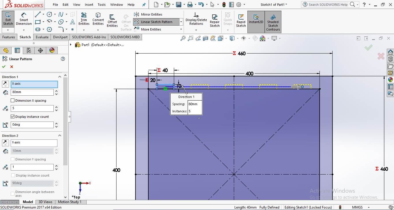
Draw the Small rectangle click on linear pattern sketch then select the sides of rectangle and add the number & degree.
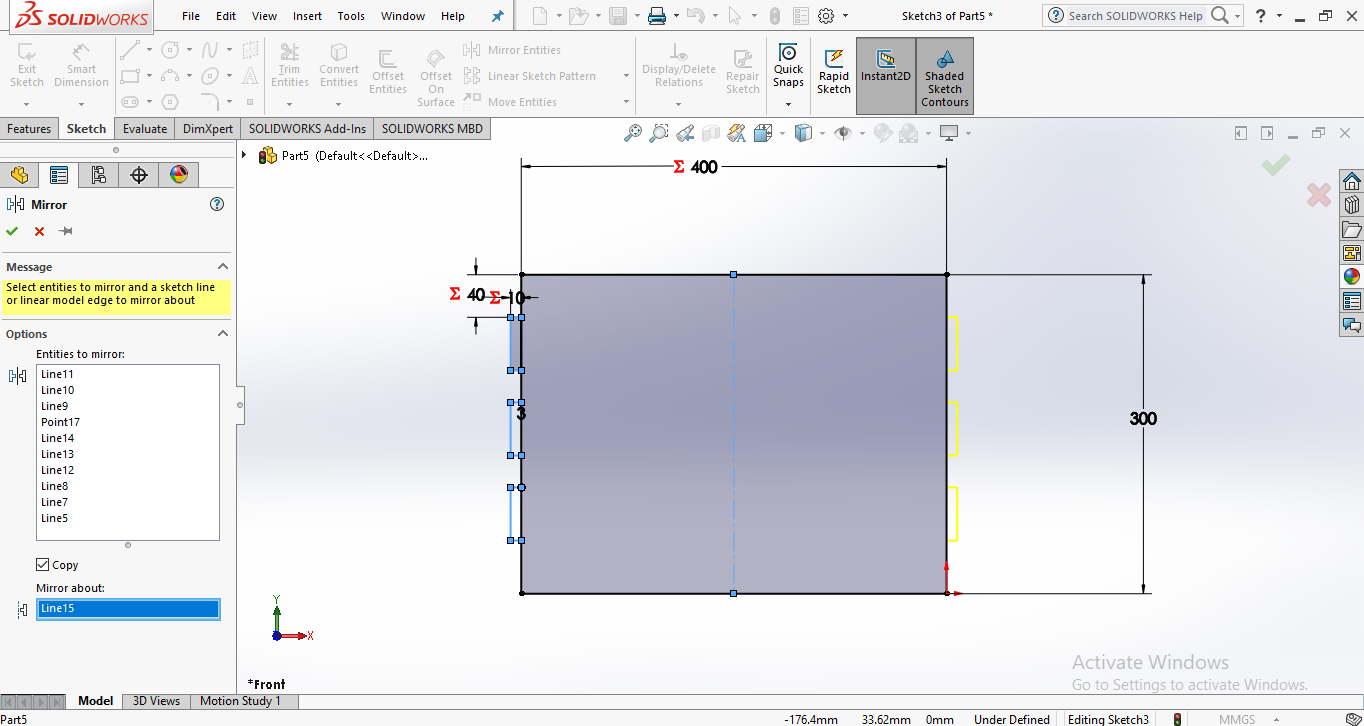
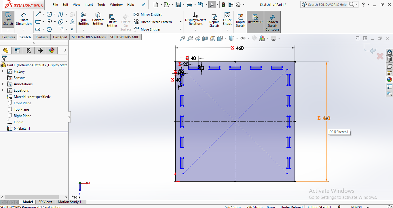
MIRROR THE ENTITIES
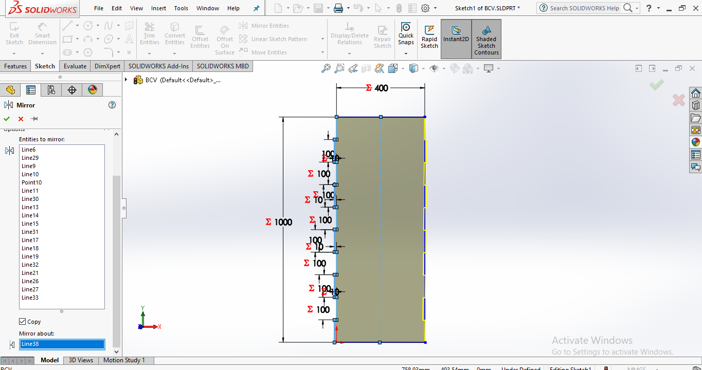
click on mirror entities select the sides of rectangle you want to mirror after that select the mirror about click on center line.
MAKE SLIT IN THE DESIGN
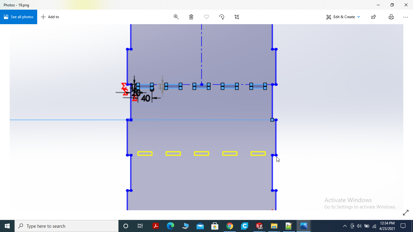
We want press fit design so I am going to make slit. the teeth of the other part will press fit with the slits.
MAKE TEETH IN THE DESIGN
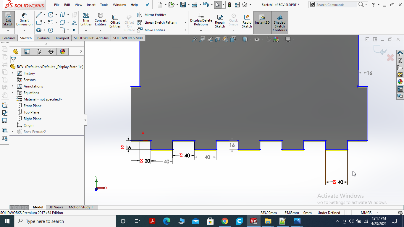
I made the teeth to attach it with the Base of the News paper Stand. We want press fit design so I am going to make slit 16mm wide.
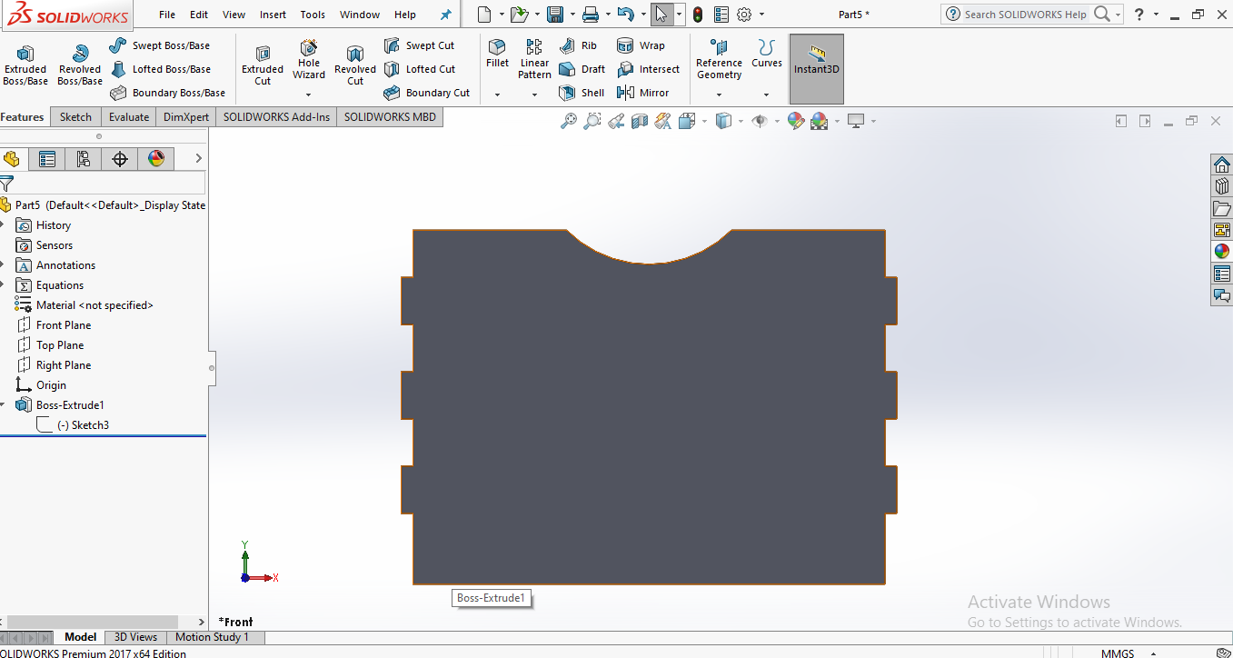
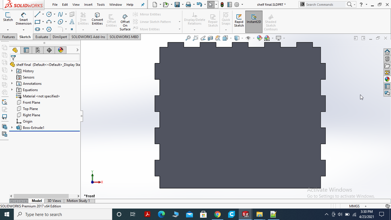
After all the changes I made inside the sketch for shelf and other parts.
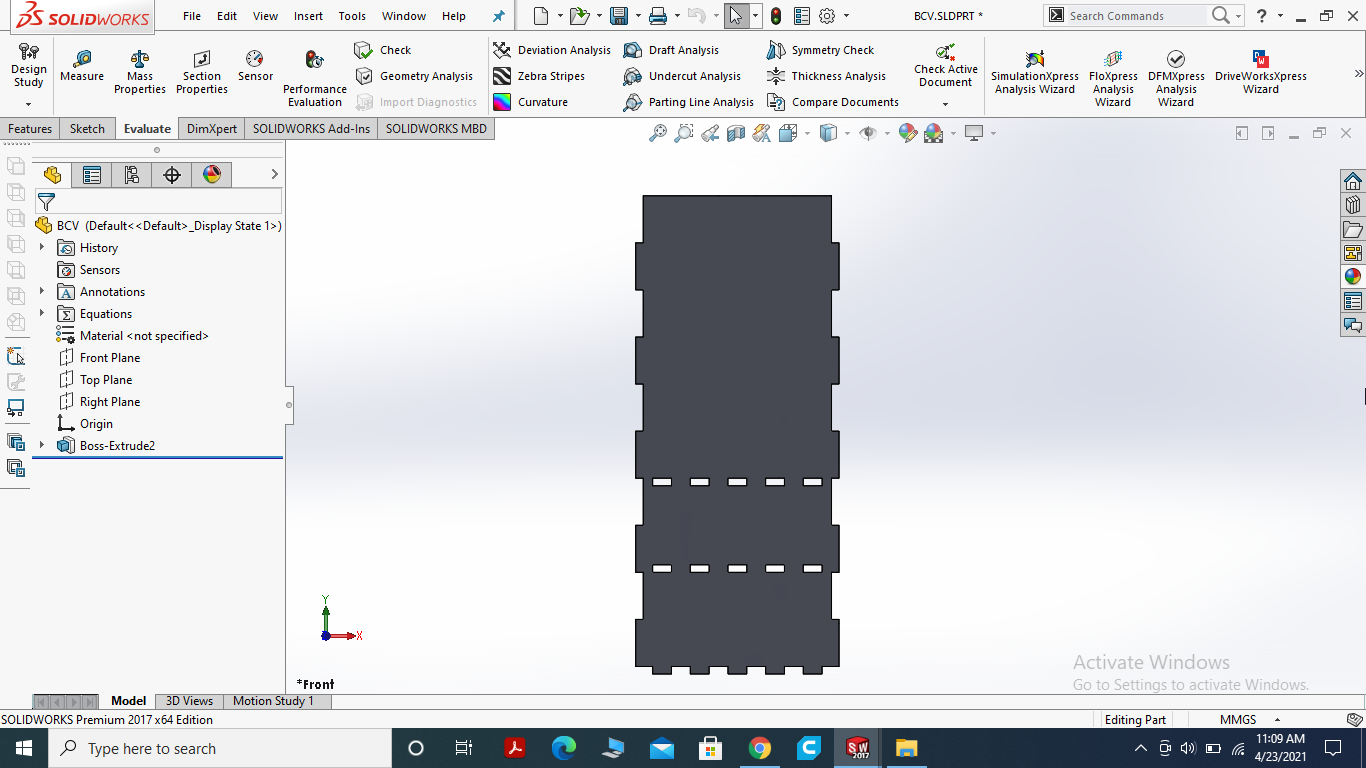
Final result of the Backside of News Paper Stand.
SIDES OF THE NEWS PAPER STAND USING PARAMETRIC EQUATIONS
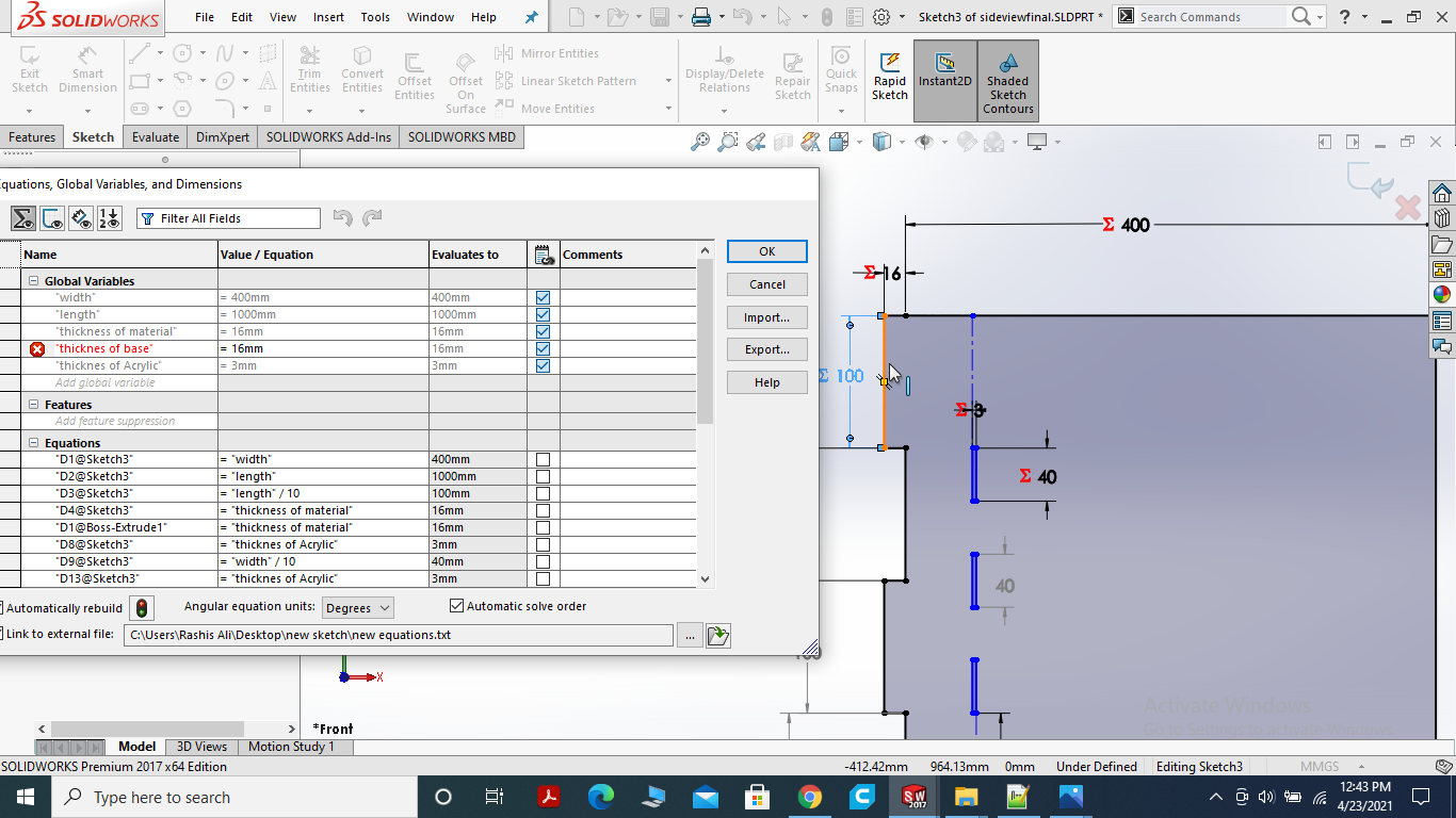
I got problem in the Equation I'll fix it. I made the slit for news paper holder. Acrylic sheet will be used.
FILET THE SIDES
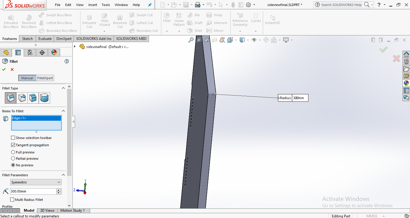
I filet the sides with 300 raduis to look better.
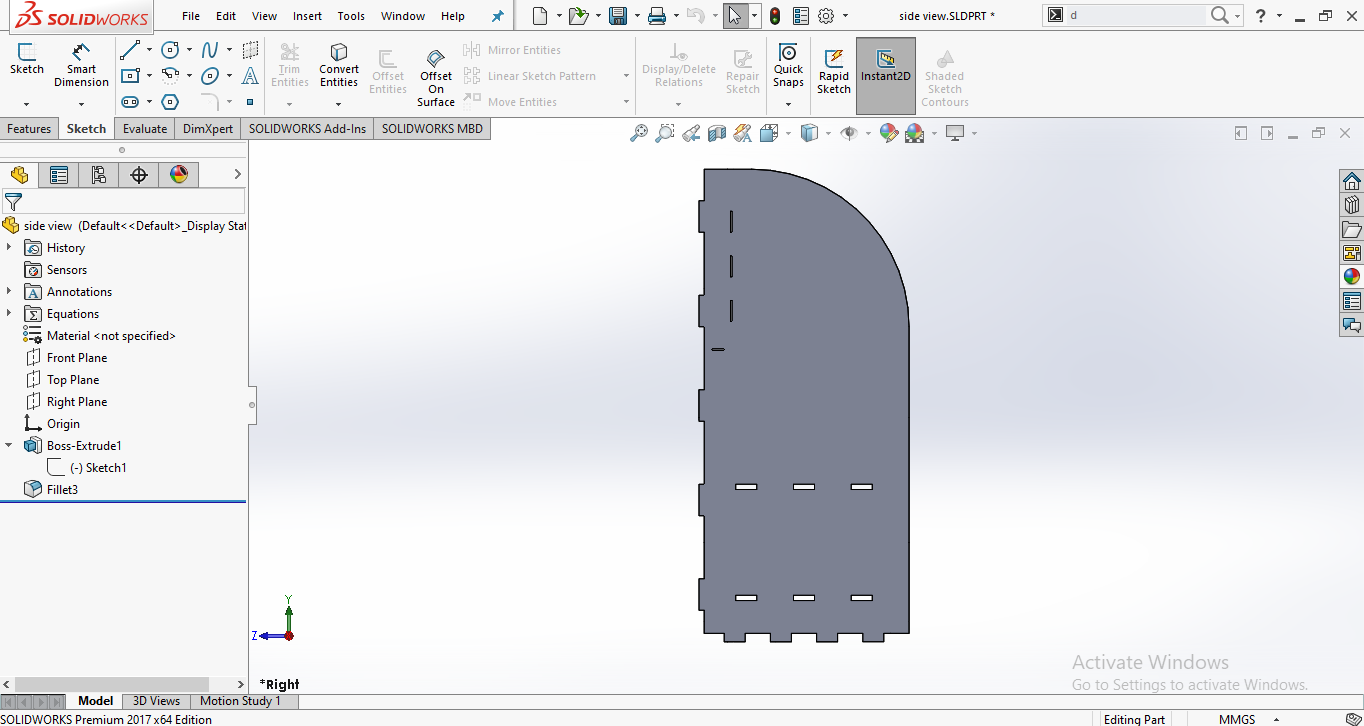
Final view of the side.
MEASURING THE NEWS PAPER WIDTH

First of all calcualte the length and with of the Dawn News Paper.
Simply I made ractangle with cacualted dimensions and make them parametric. I made the teeth using linear sketch and mirror command.
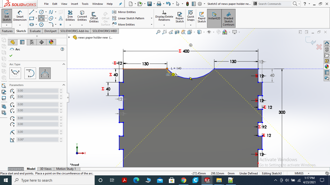
Here, I used 3 point circle to make the curve. it will be easy to pick the paper.
For news paper holder I decided to cut it with Acrylic sheet it will give the better look for display.
MAKE STRIP (SUPPORT FOR PAPER)
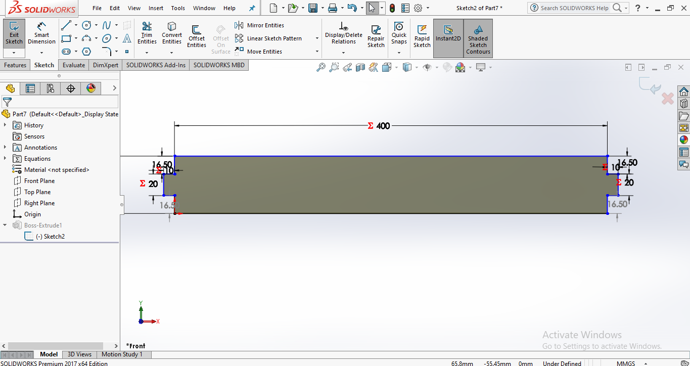
Strip will hold the news paper from ground size and will not allow to fall.
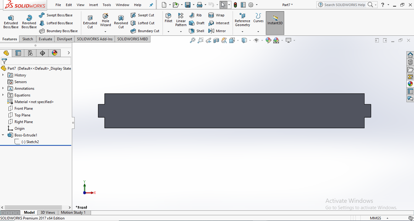
Piece of the Strip will also be made up of the Acrylic Sheet.
THE SHELF
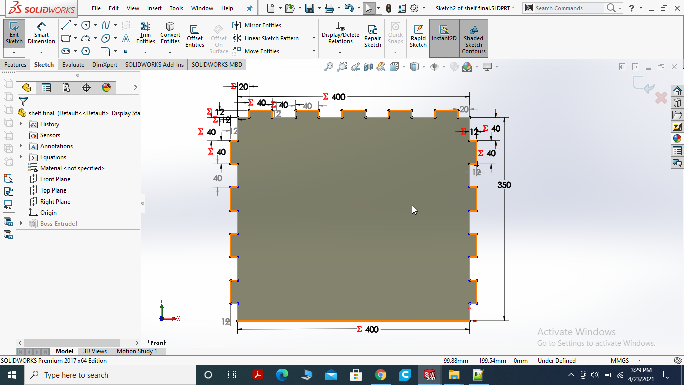
Here, I made the teeth in 3 sides of rectangle one side will fix with backsize of paper stand and other 2 sides will fix with left and right size of the stand.
made the shelf parametric and then extrude boss.
THE BASE
Draw the Rectangle draw an other Rectangle inside it.
for linear sketch pattern draw the small rectangle then give the direction and count the number you want to draw.
draw the slits on three sides.
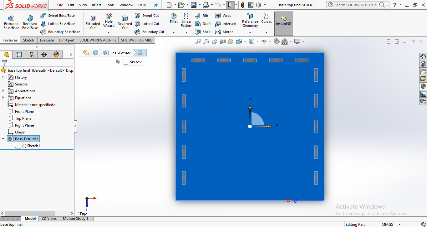
Now, extrude boss the base.
THE ASSEMBLY
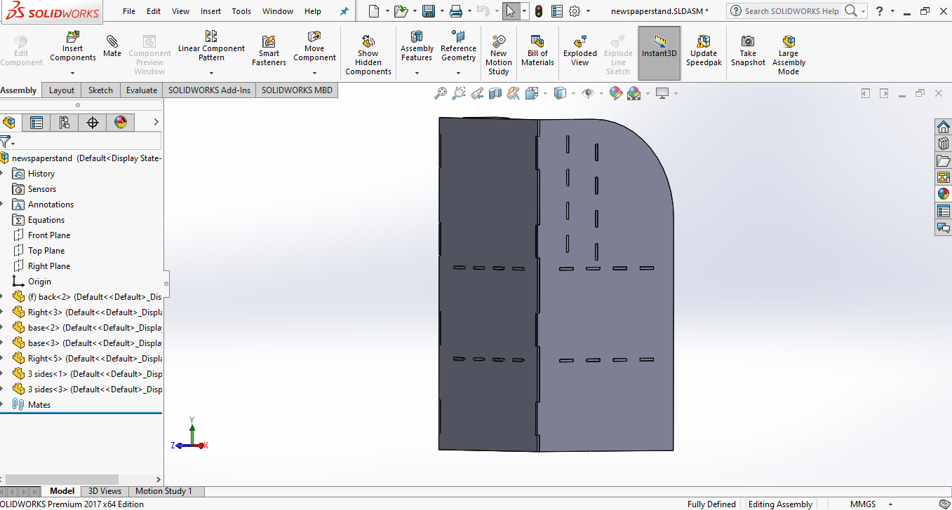
Here, we mate the parts to each other. Backside and 2 sides of the news paper stand mated.
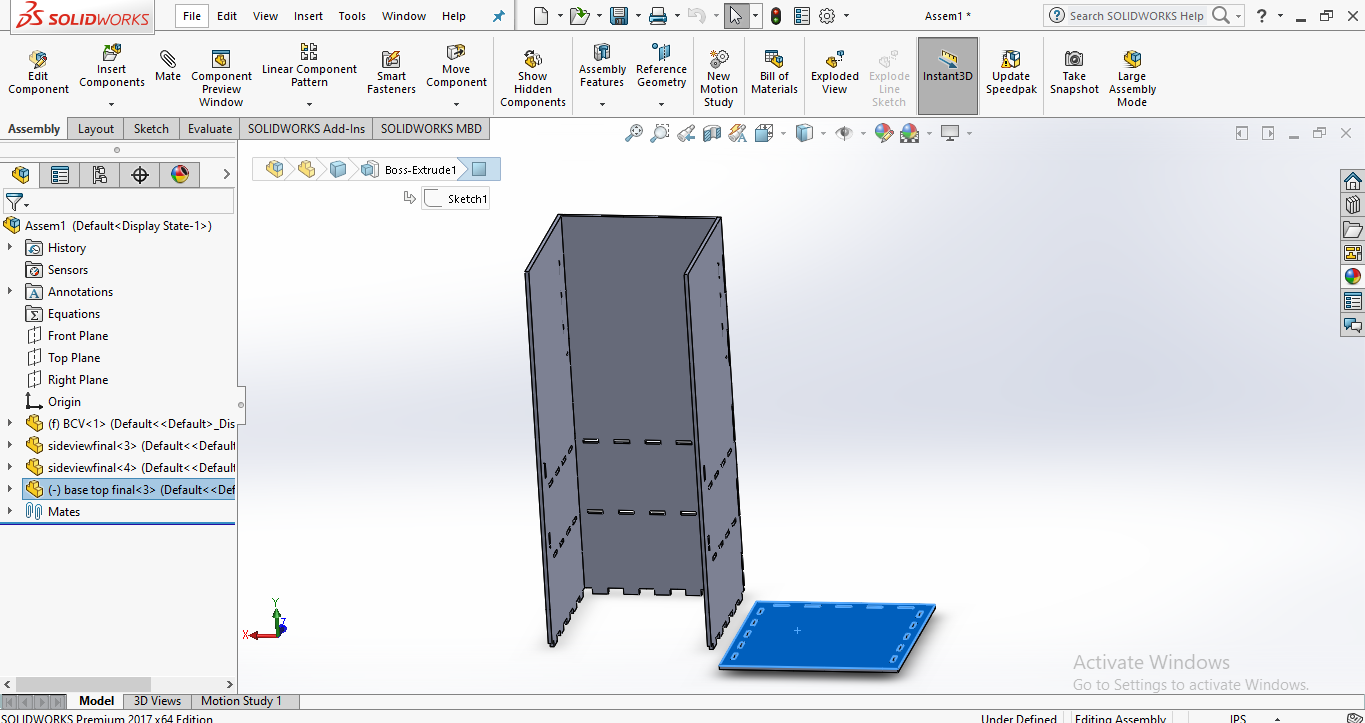
Assembling the base of paper stand.
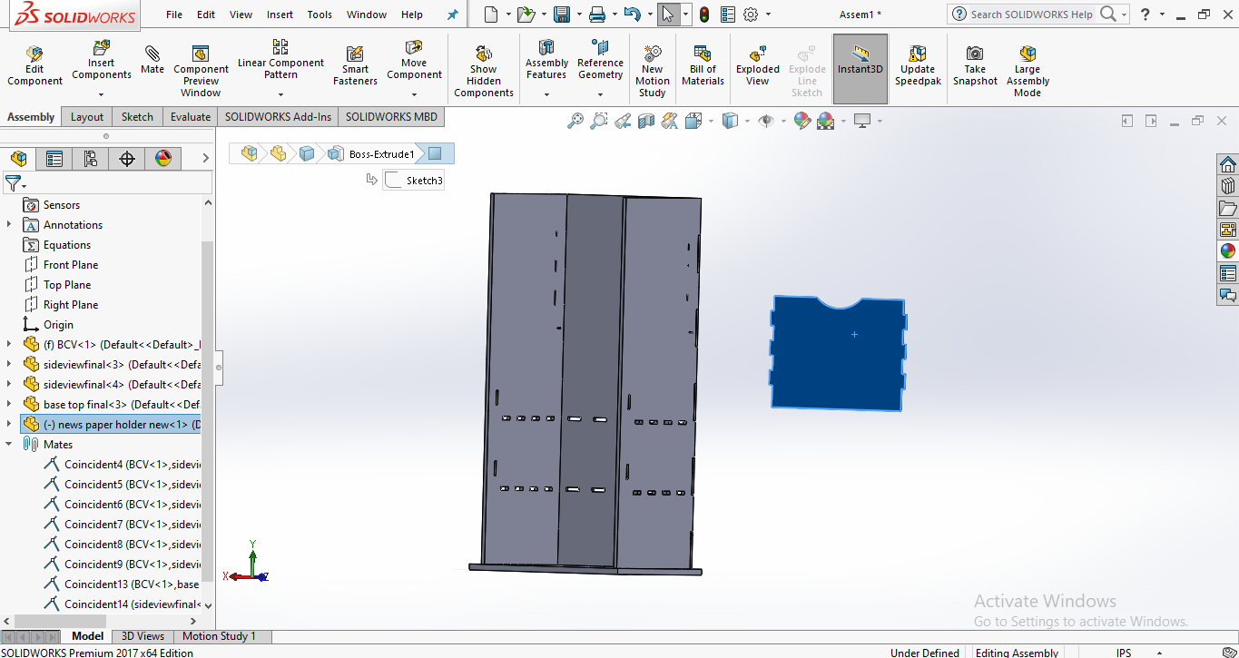
Assembling the paper holder.
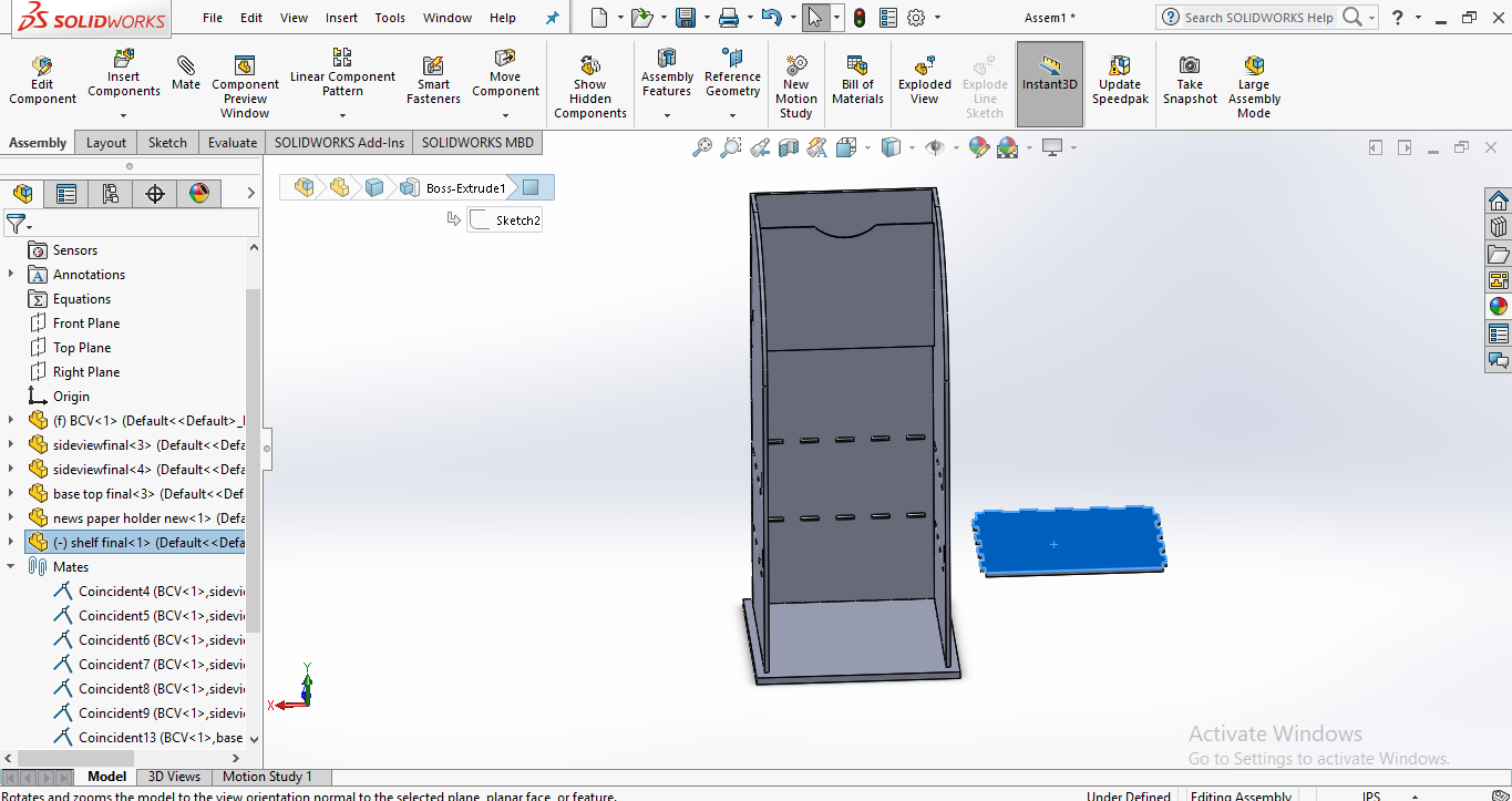
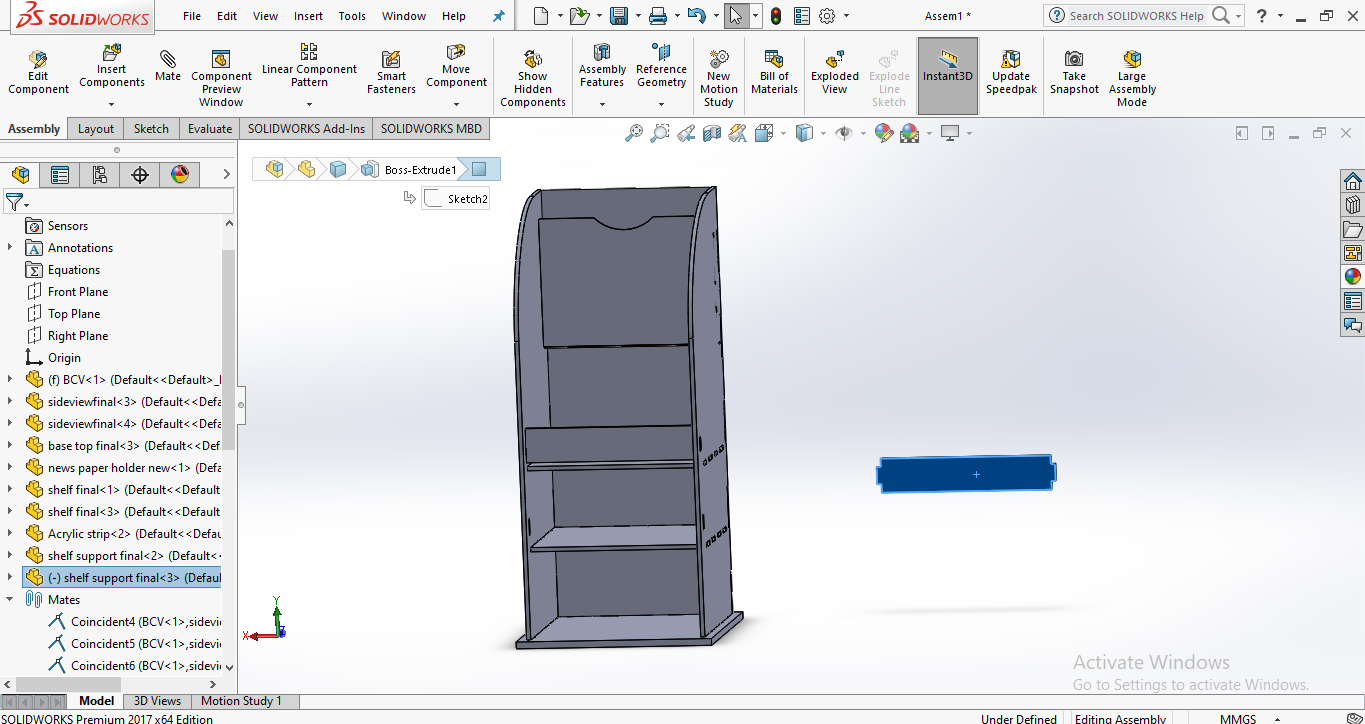
Assembling the shelf.
Assembling the strip.
FINAL 3D DAIGRAM OF NEWS PAPER STAND
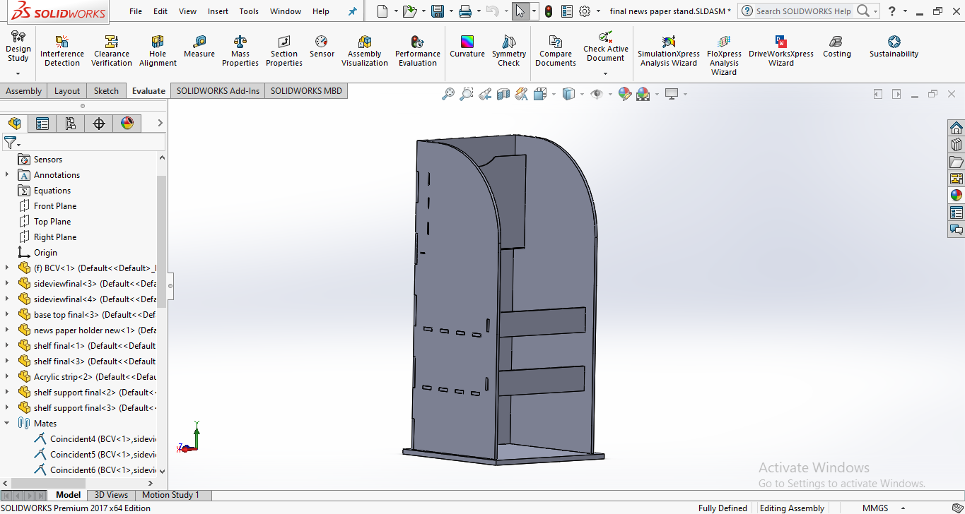
Now, 3D diagram is ready to for shopbot.
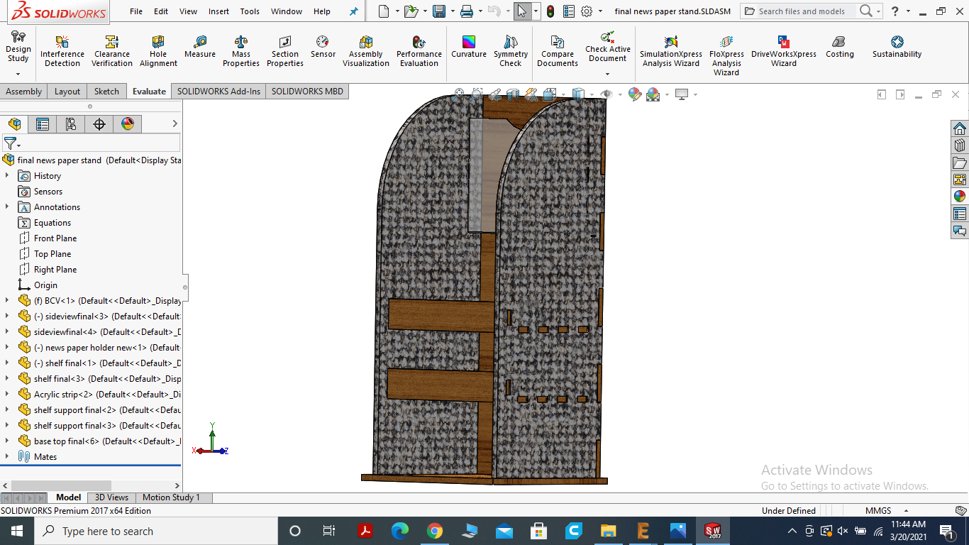
Real time Graphics view of the news paper stand.
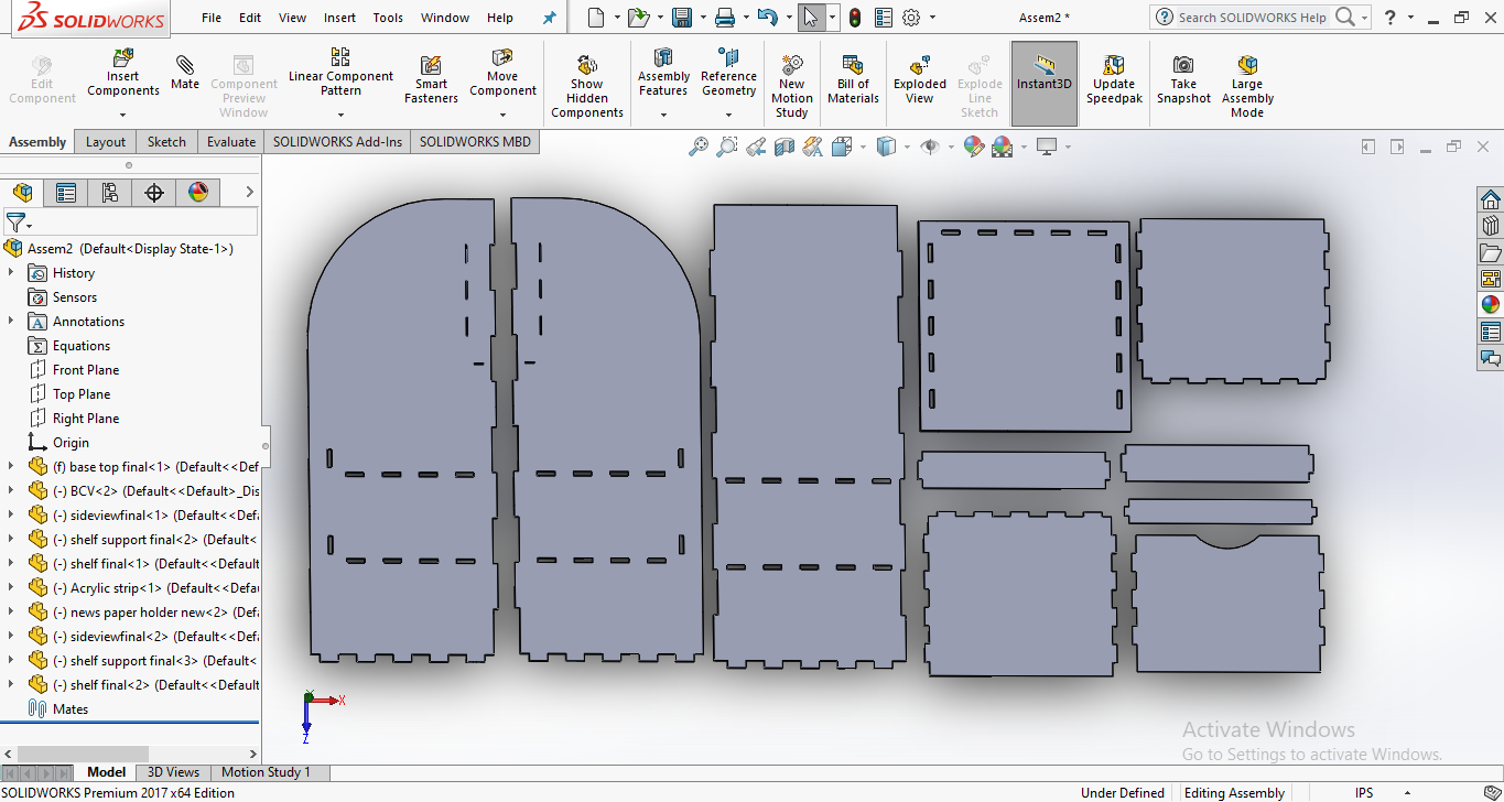
Assembling all parts together.
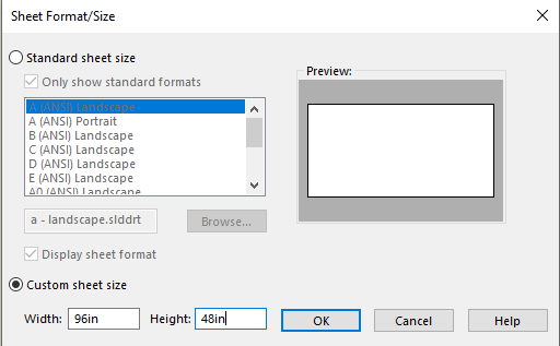
select the custom sheet size whose width=96 inches and length=48 inches.
SAVING FILE AS .DXF FILE
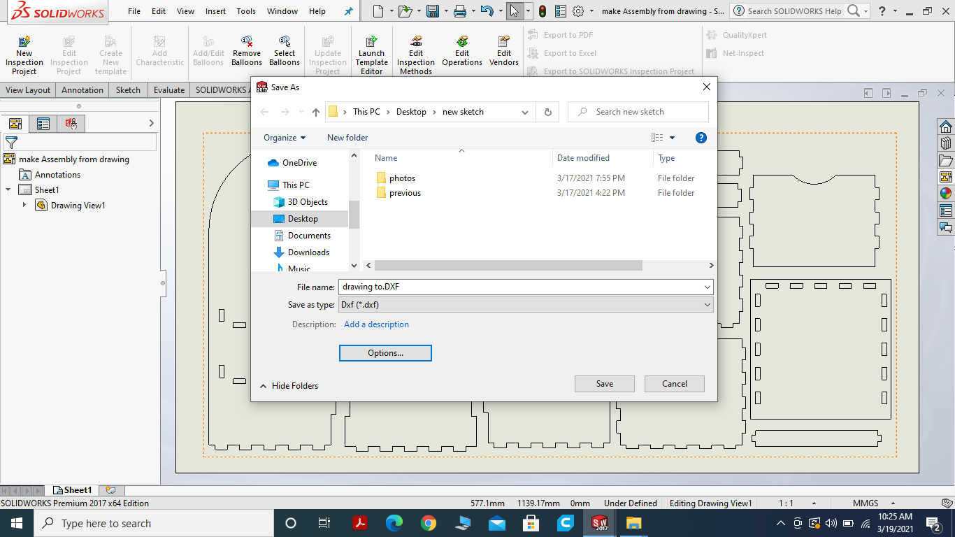
saving solid works assembly file in.dxf for Vcarve.
MEASURE THE THICKNESS OF CHIPBOARD
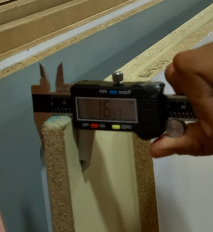
The thickness of material is about 16.53mm
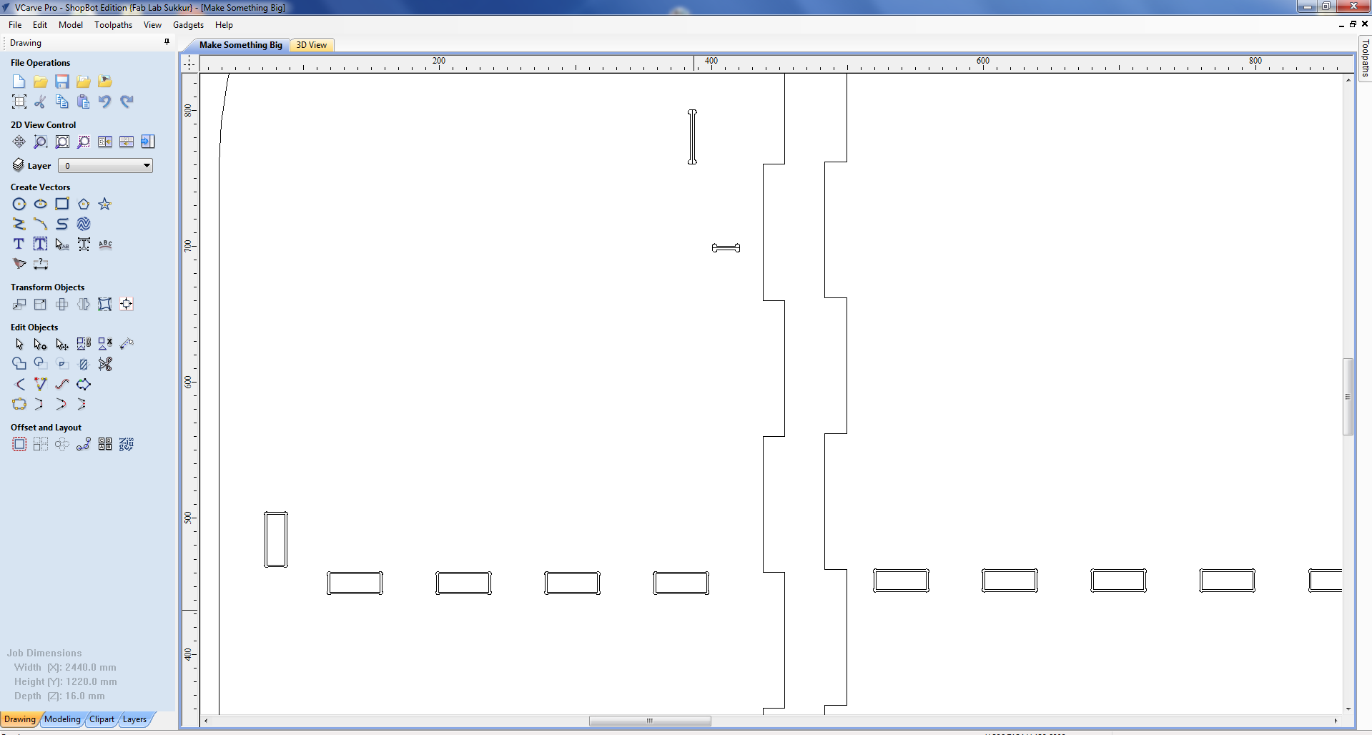
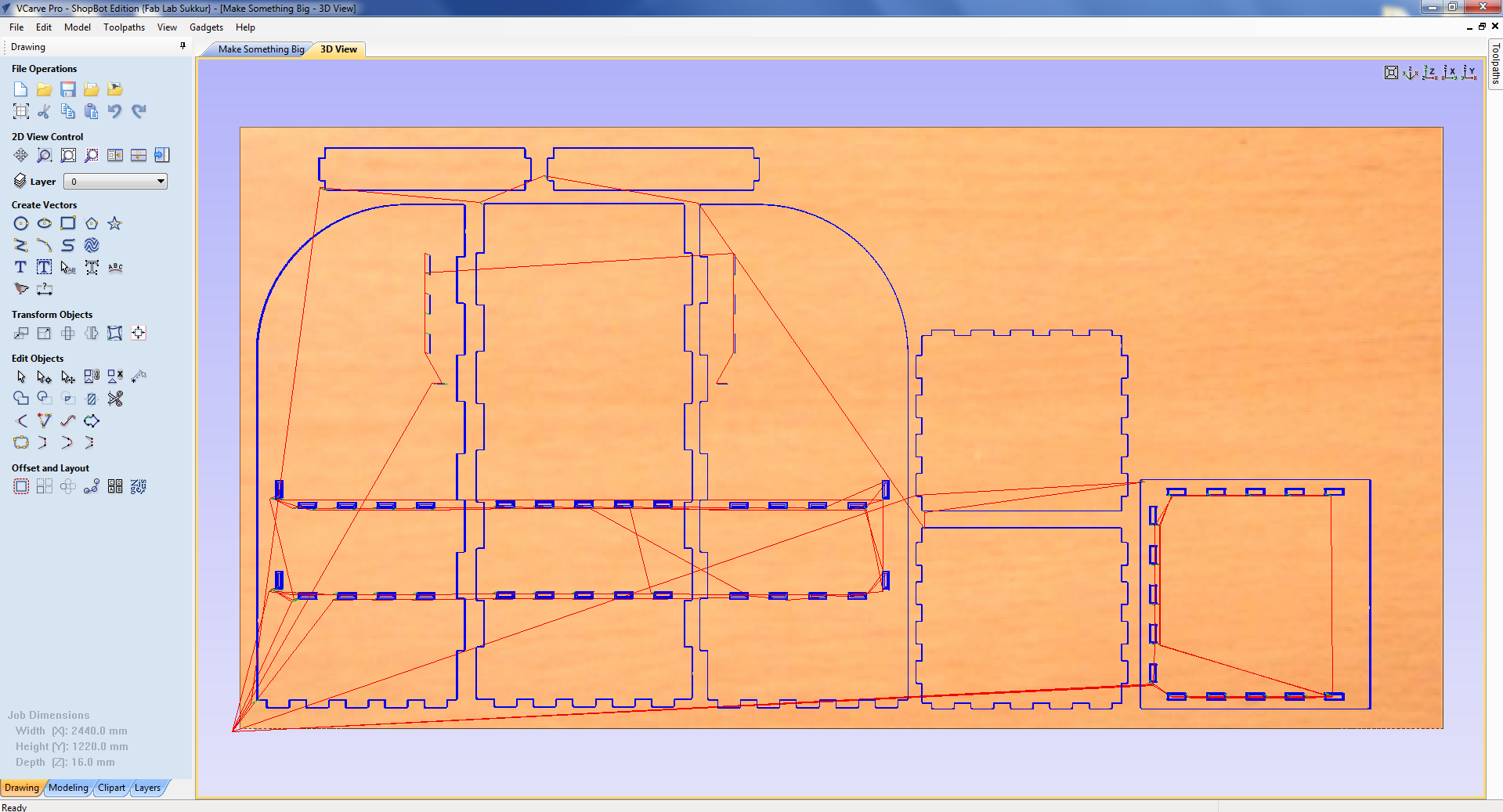
VCARVE SOFTWARE
I choose Vcarve for tool path generation. VCarve Pro provides a powerful but intuitive software solution for creating and cutting parts on a CNC Router. VCarve Pro gives you the power to produce complex 2D patterns with profile, pocket, drill and inlay tool paths. Along with this, it gives you the ability to create designs with v-carving textures as well as import and machine unlimited Vectric 3D clipart or single model files. The ‘Pro’ edition gives you unlimited job and tool path size, true shape nesting & job set-up sheets, ideally suited to a production environment.
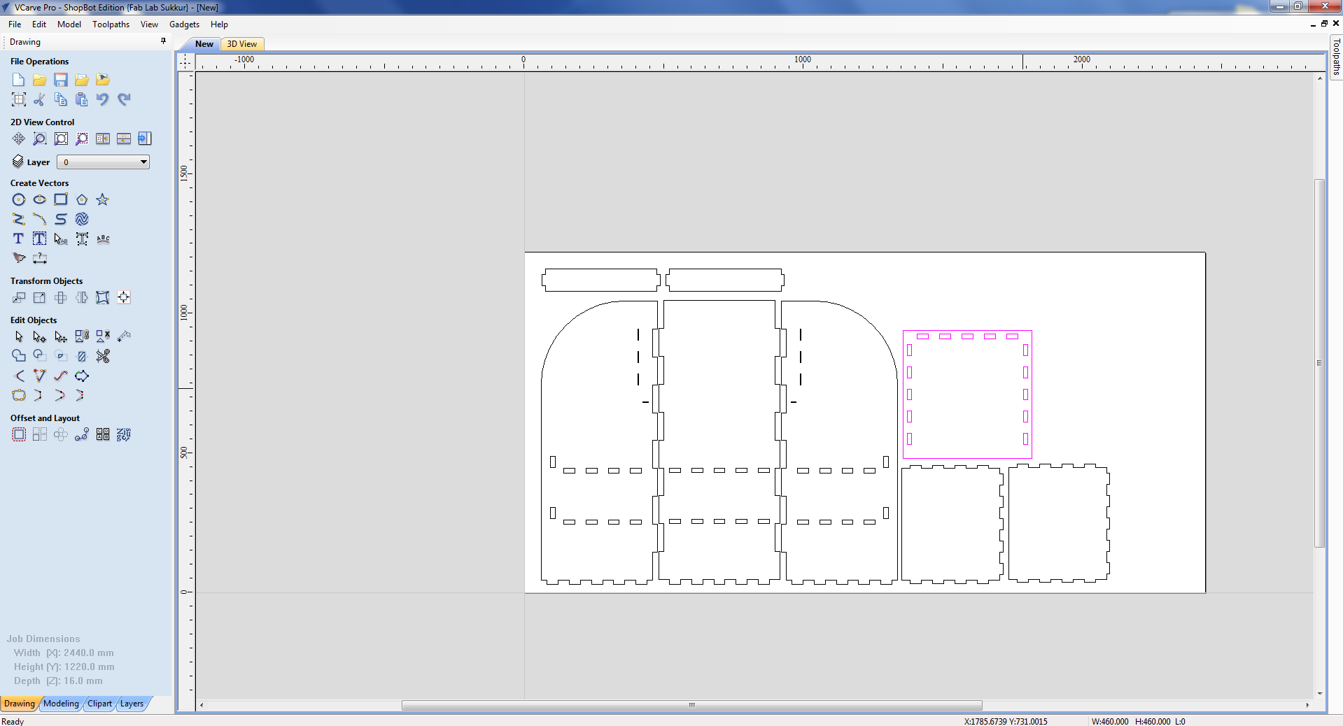
Open the vcarve software and drag the .dxf file into it.
Grouping the outer layer/line of all the parts and created the 20mm space of guide layer for being on safe side.
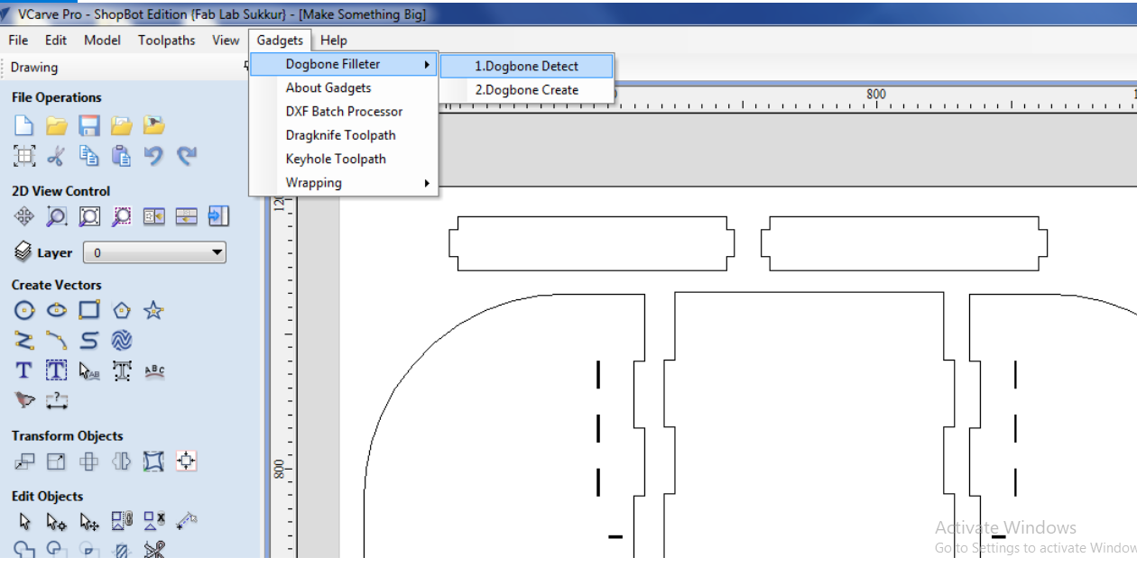
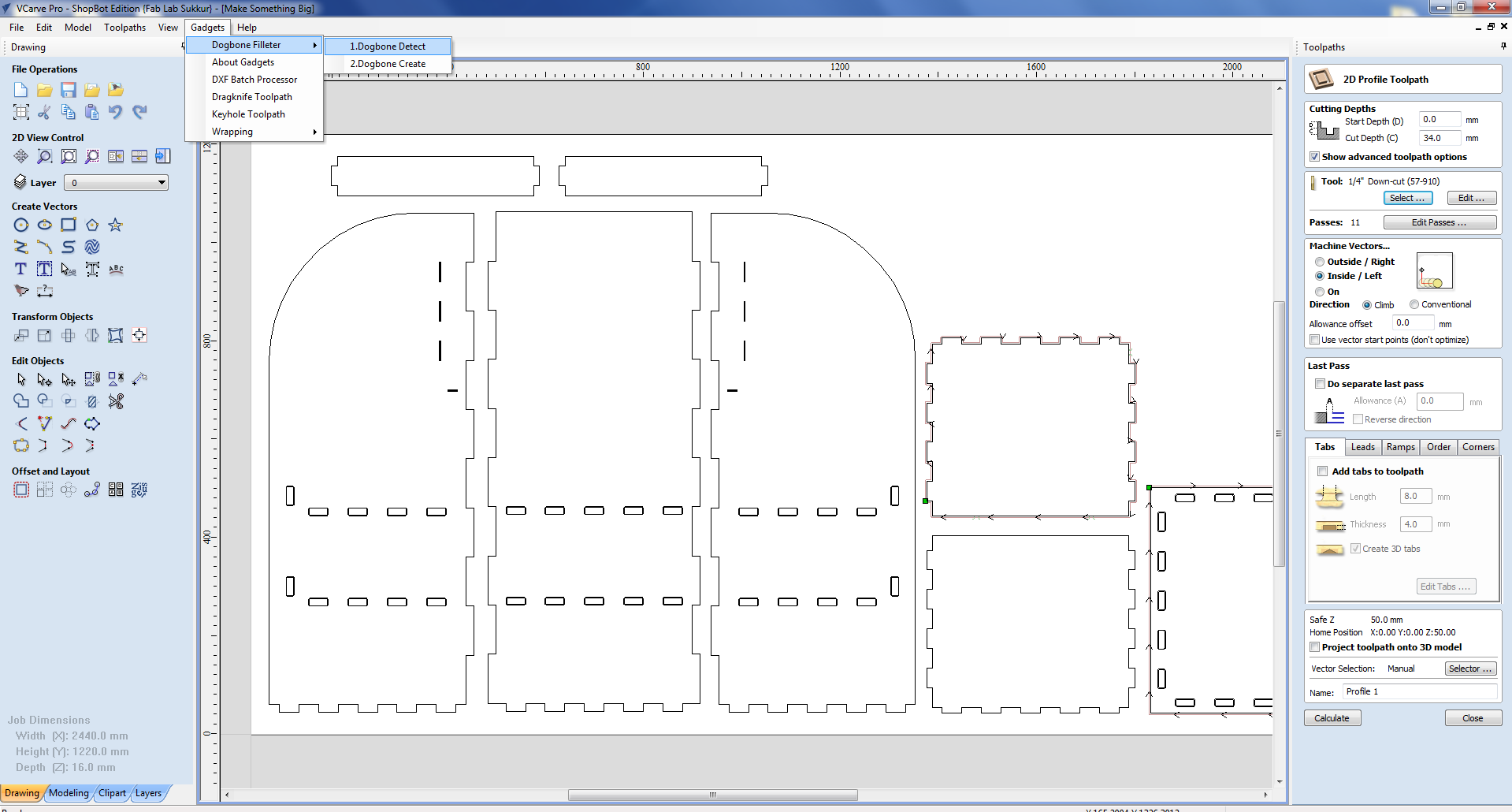
Now we select the dog bone because I want my object parts to fit tightly with each other.
Grouping the Slits of the Design for dogbone.
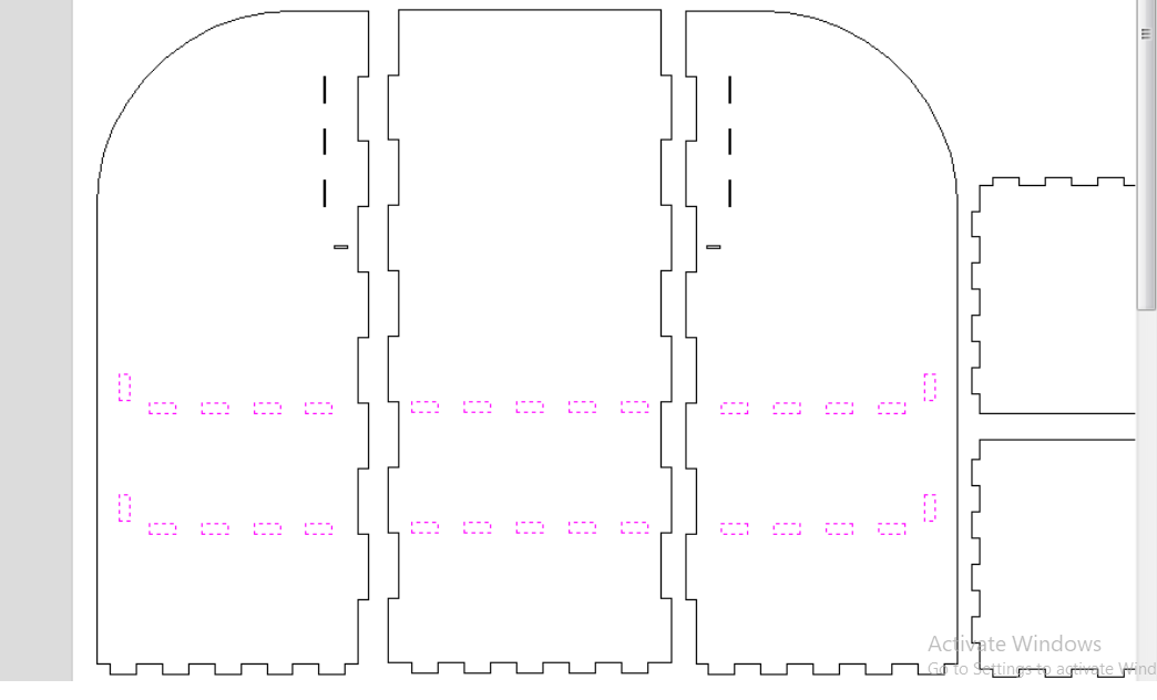
result of the dogbone in the slits.
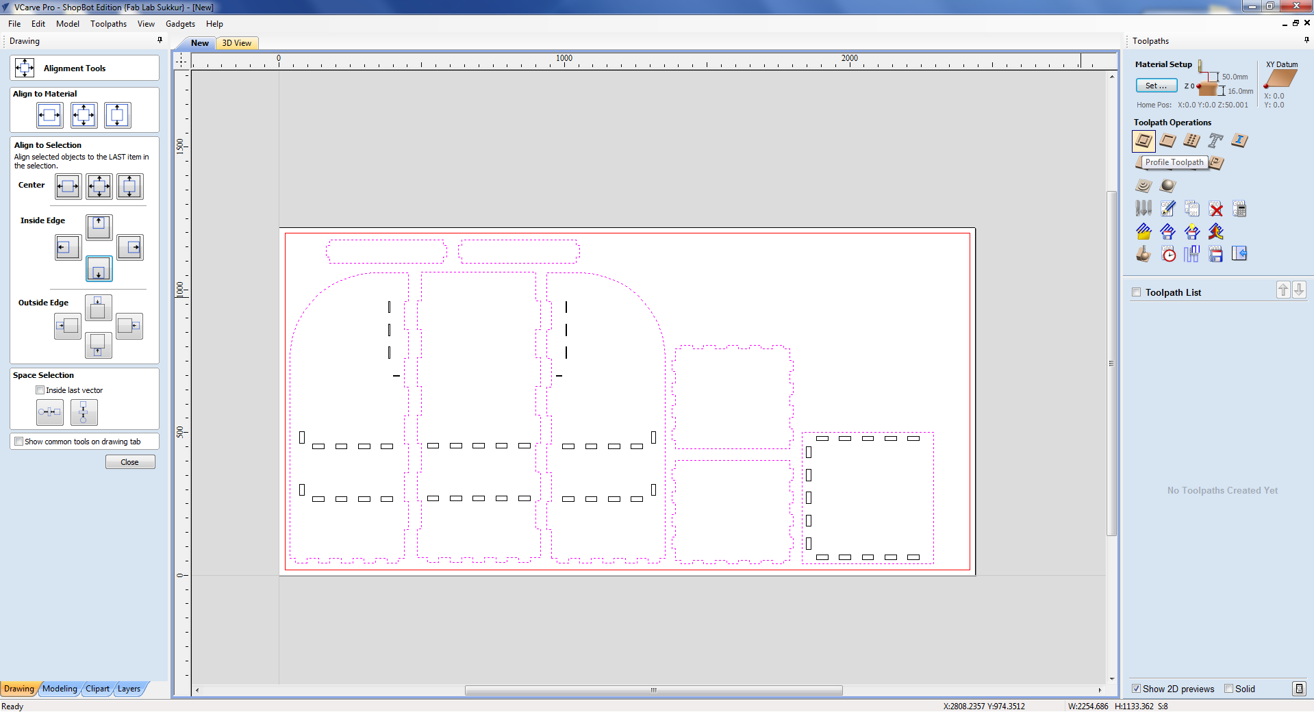
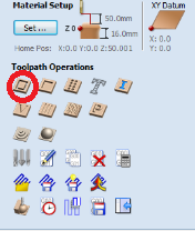
TOOL PATH SETTING
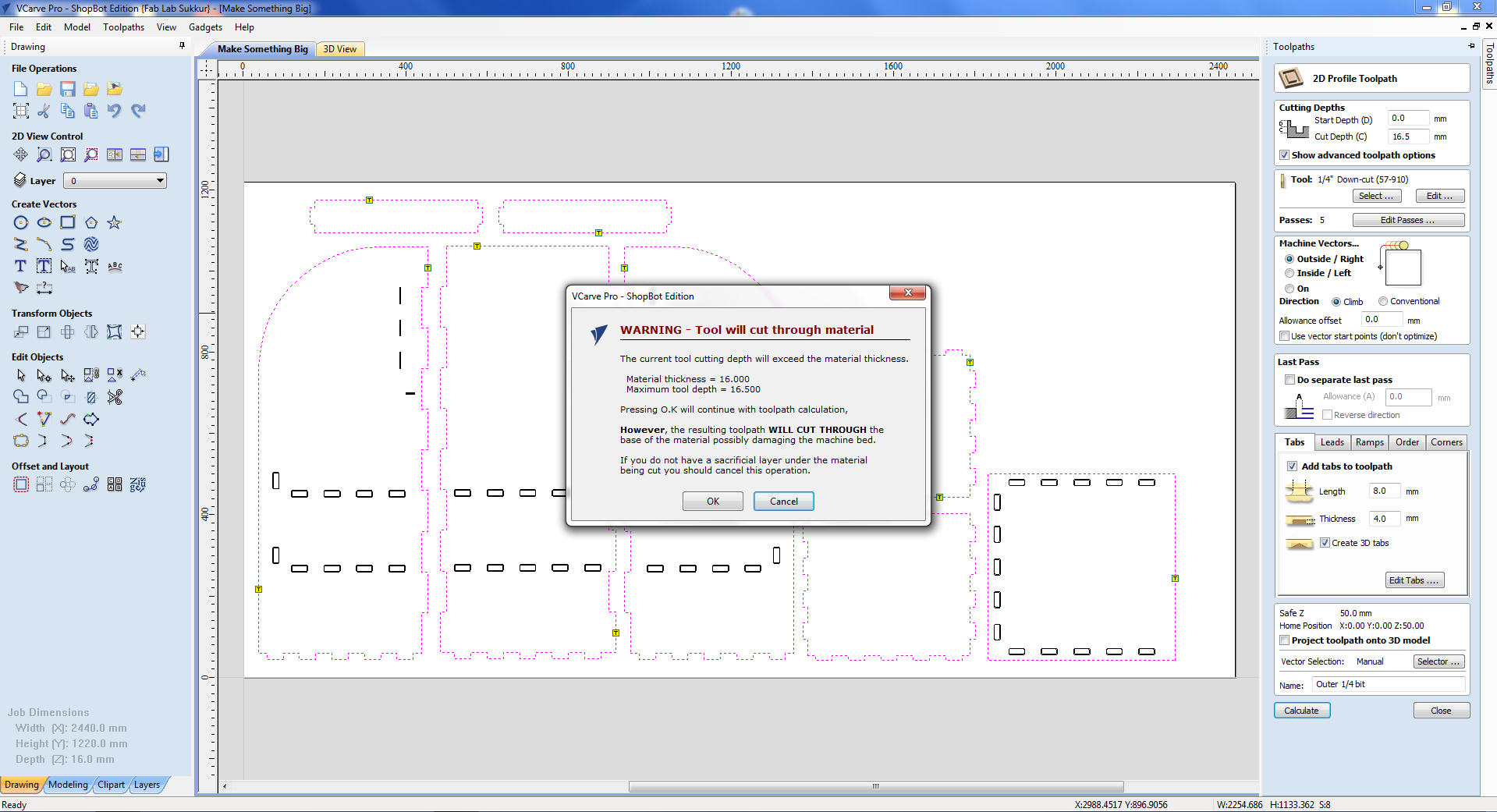
After material and XY setting now click on tool path profile. New window will apprear. Setting of toolpath will be done here. First of on the top is cut dept setting. We want to cut through so start cut should be "0" and cut depth should be greater than thickness of material. Material thickness is 16mm so I put cut depth 16.5mm. Please note that Shopboat must have sacrificial layer.
This is the Profile tool path.
TOOL TYPE
Before selecting the tool for our job let's learn more about tools type. There are various types of CNC cutting tools and these tools are designed for high-precision machining. Most often, manufacturers make use of CNC cutting tools for near-perfection projects requiring a high degree of accuracy and precision. Which of the CNC cutting tools used is dependent on the project, operation pattern, and, most importantly, the CNC machine itself. Some CNC cutting tools are:
END MILLS
Rotational cutting tools that you can use for the removal of materials. Although very similar to the drill bit, the end mill is for more versatile machining operations. Unlike the drill bit that cut axially to the material, end mills are lateral cutting tools that cut in any direction. Due to their design, some end mills cannot cut materials axially. Generally, there are different types of tip shapes for an end mill and each end mill depends on the desired end-product.
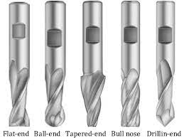
End mills bit types and there are much more.
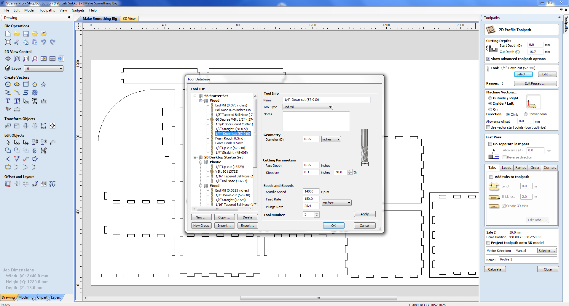
SELECT THE TOOL
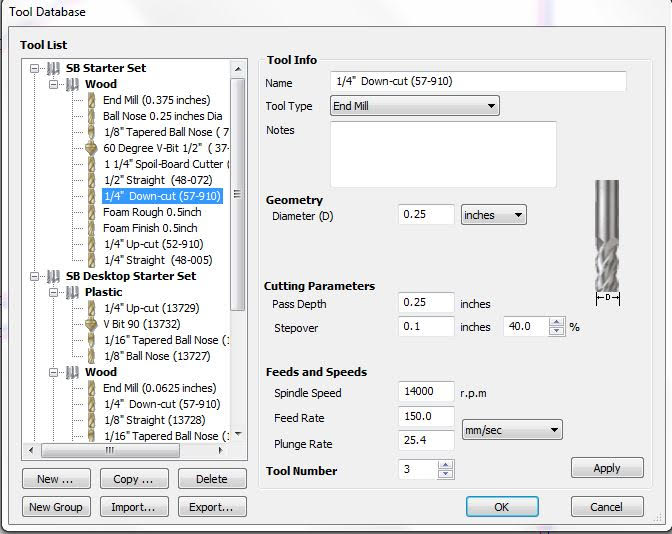
I am using 1/4 downcut end mill. It has diameter of 0.25inch. Spindle speed of 14000rpm, feed 150mm/sec. It has two fluets.
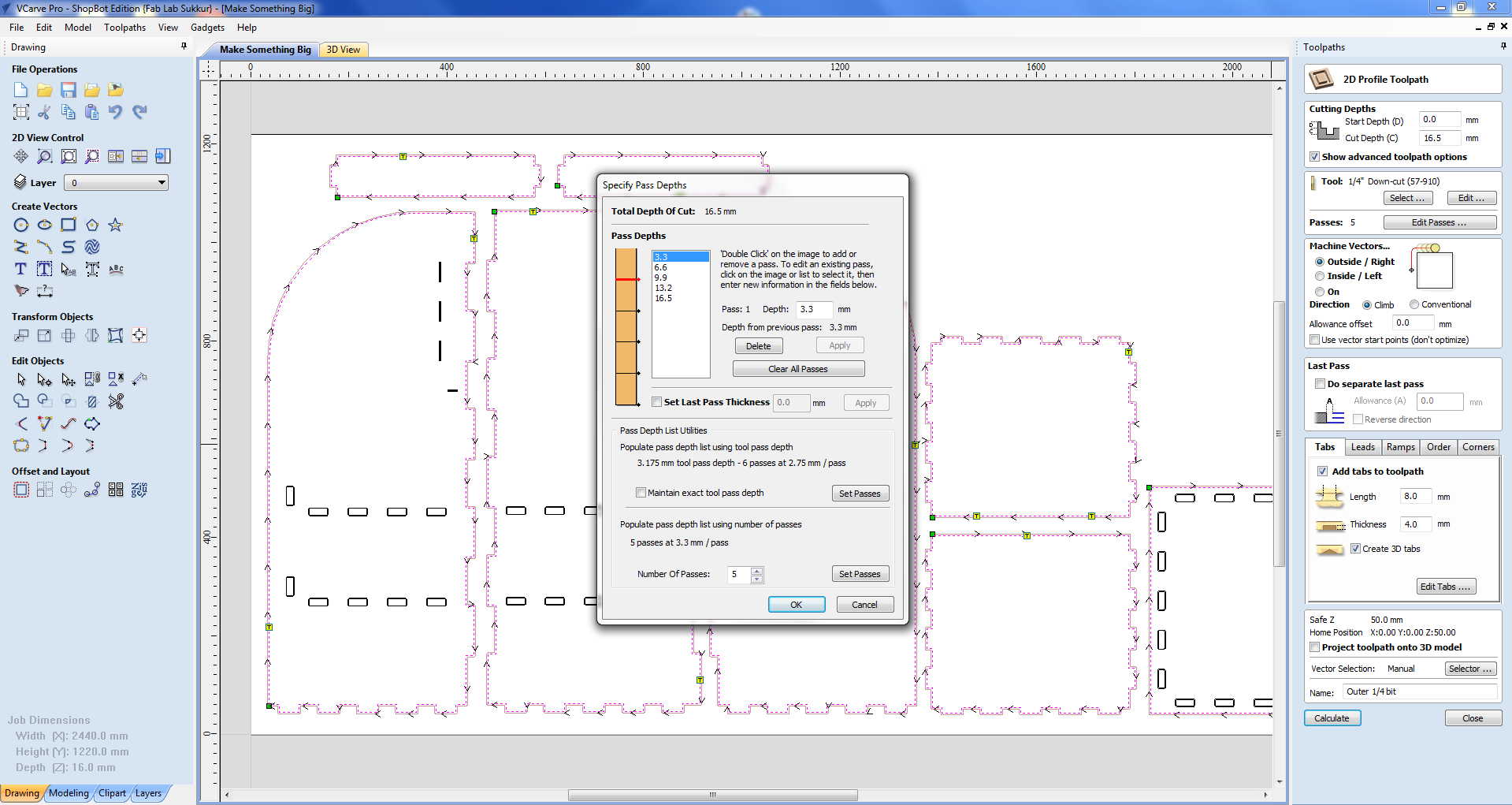
PASS DEPTH
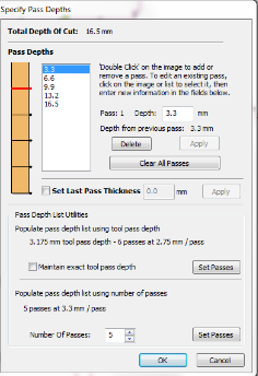
Your "depth per pass" settings can also cause bits to break. As a rule, your depth per pass should never exceed half of your bit's cutting diameter. I am using tool of diameter 6.35 so pass depth should be around the half of it. SO I choose 6 passes with 3.175mm depth.
MACHINE VECTORS
OUTSIDE CUT
Tool cuts through the material, running along the outside of a closed line in a manufacturing document/ blueprint.
INSIDE CUT
Tool cuts through the material, running along the inside of a closed line.
ON-LINE CUT
Tool cuts through the material, running along the inside of a closed line.
CLIMB
Climb milling is when the direction of cut and rotation of the cutter combine to try to “suck” the mill up over (hence it's called “climb” milling) or away from the work. It produces the best surface finish.
COVENTENTIAL
In Conventional Milling, the cutter rotates against the direction of the feed. During Climb Milling, the cutter rotates with the feed. Conventional Milling is the traditional approach when cutting because the backlash, or the play between the lead screw and the nut in the machine table.
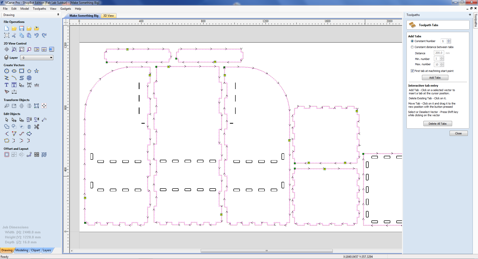
Adding the tabs because desire parts will not come out from the big sheet of the chipboard.
Now creating the tool path we move towards the profile tool path. selecting the outside, Inside, or On tool depends on which path is most suitable for design.
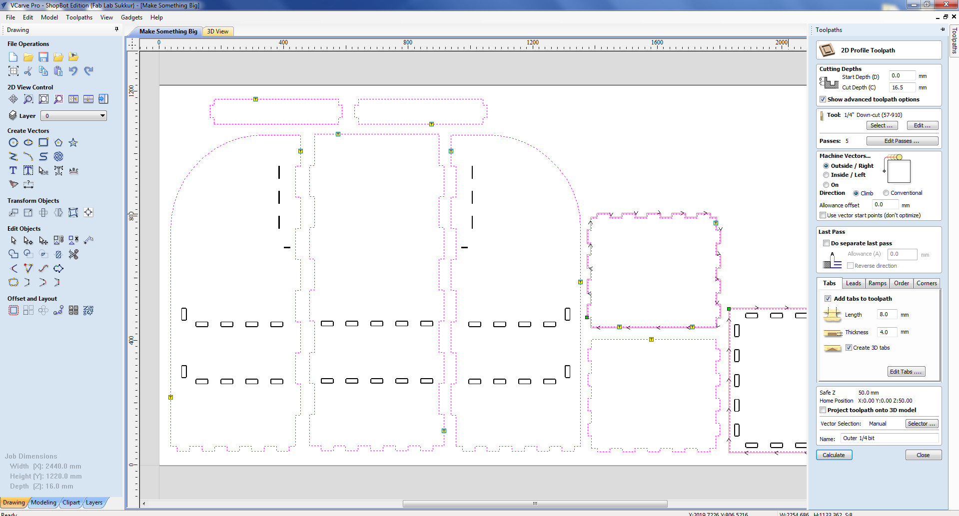
for outer boundry of the design I selected the outside tool.
In toolpath settings we set Cut Depth as 16.5mm, Set Machine to run outside vectors, selected 1/4" Down-cut (57-910) drill bit and add tabs which help part to not move from place while cutting and then checked preview.
These are the tool path pass for the outer boundry/layer of the design.
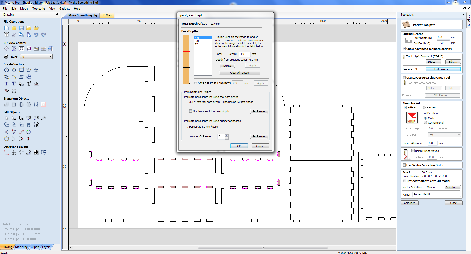
tool path passes, for pocket profile which I made in slits.
COMPLETE TOOL PATH SETTING AND SIMULATION
Here is the complete setting of toolpath. Name the tool path in below portion. Click calculate to generate the tool path and also it generate the simulations. Click ok and simulation is generated. You can play with play button. Also in left bottom you can see all the toolpaths.
preview shows the path of machine on the objects.
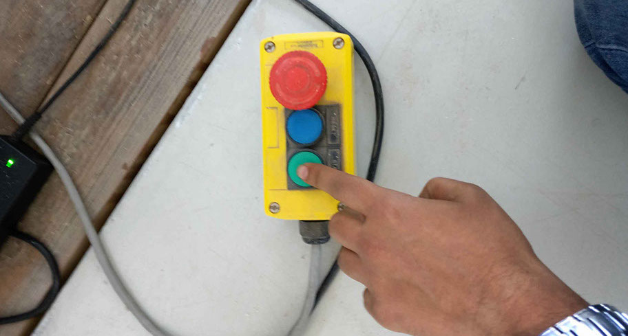
OPEN THE SHOPBOAT CONTROLLER
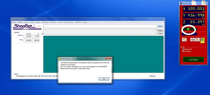
Open the shopbaot controller. LED 4 is on. We need to make it off using a start-up sequence of Shopboat. Without doing this, shopboat won't be functional.
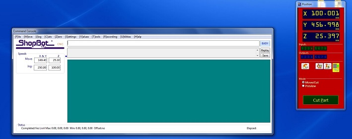
Start-up sequence is press the red button and then twist it according to arrow then press reset button. Repeat this sequence untill LED 4 is off.
SET X,Y AXIS ZERO
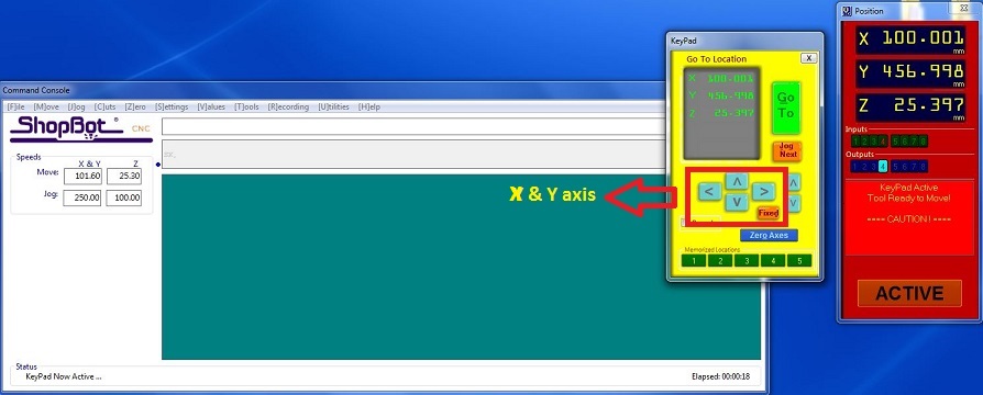
Click on keypad. New window will apprear. Move the machine head using the arrow keys and move the head on the left corner of the sheet.
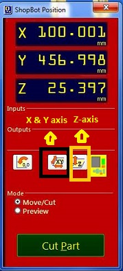
Click on "zero axis" button. Check the X,Y and click the zero. X, Y axis are now zero.
SET Z AXIS ZERO
Click Z-axis zero highlighted above.
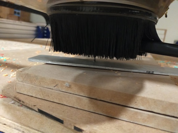
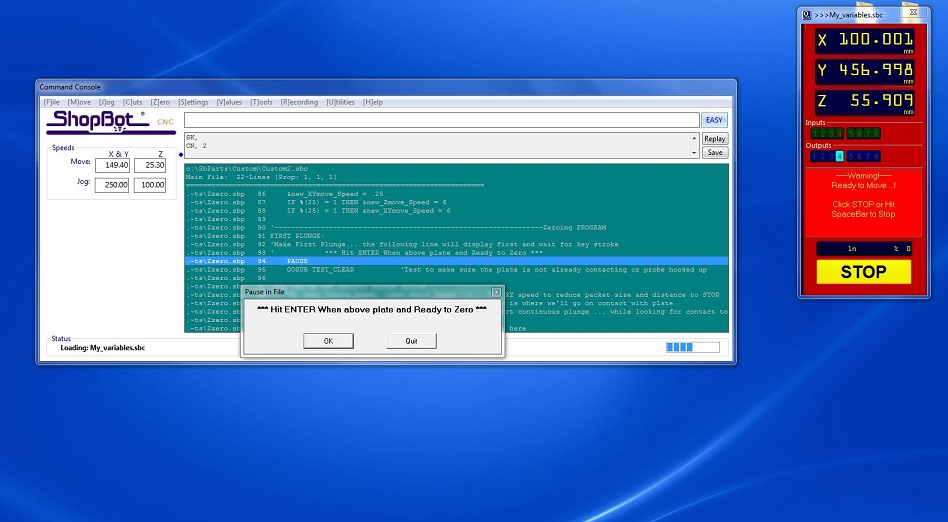
Take a build plate and crocodile clip. Put the plate below the tool on the wood. Put the crocodile clip on the tool clap. After setting all this correctly hit enter. Tool automatically comes done and hit the plate then goes up then again goes down.
OPEN THE TOOL PATH FILE AND START THE JOB
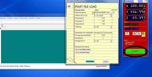
Click on the "Cut part". New window will be opened. Select the tool path file generated from Vcarve. Click open. Now file is loaded. Click the start to start the job.
START THE SPINDLE
Now notification will be arrive to start the spindle. First open the vaccum then push the start button on the Shopboat controller.
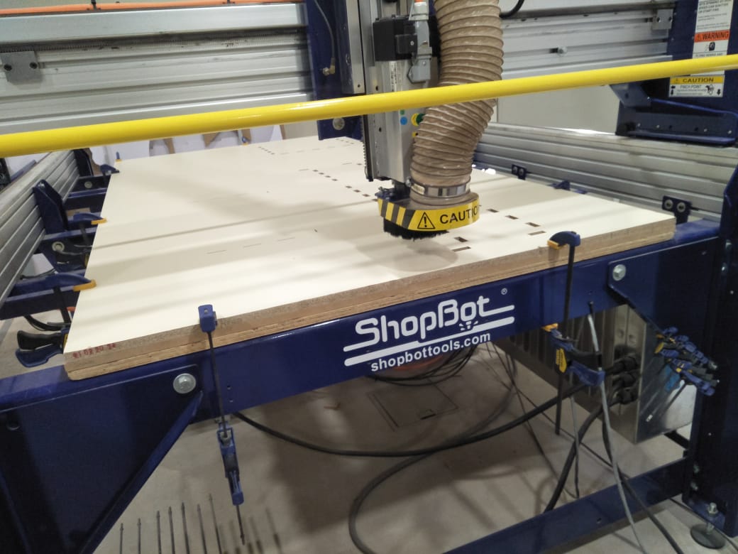
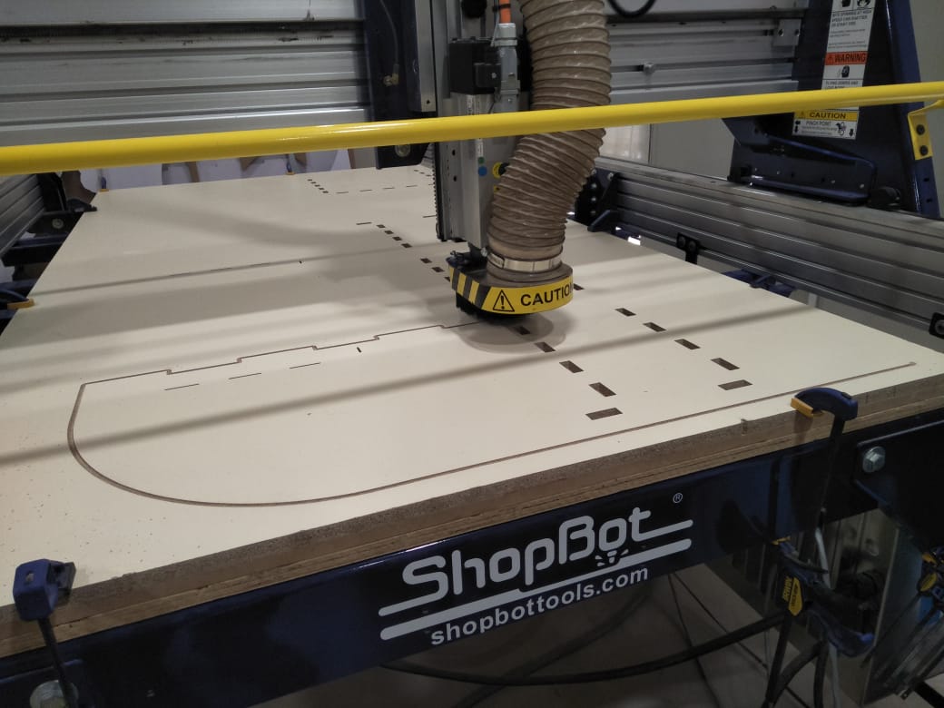
CUTTING ON SHOP BOAT
I gave the file of slit which will make the pocket inside the slit.
Sarted cutting the outer tool.
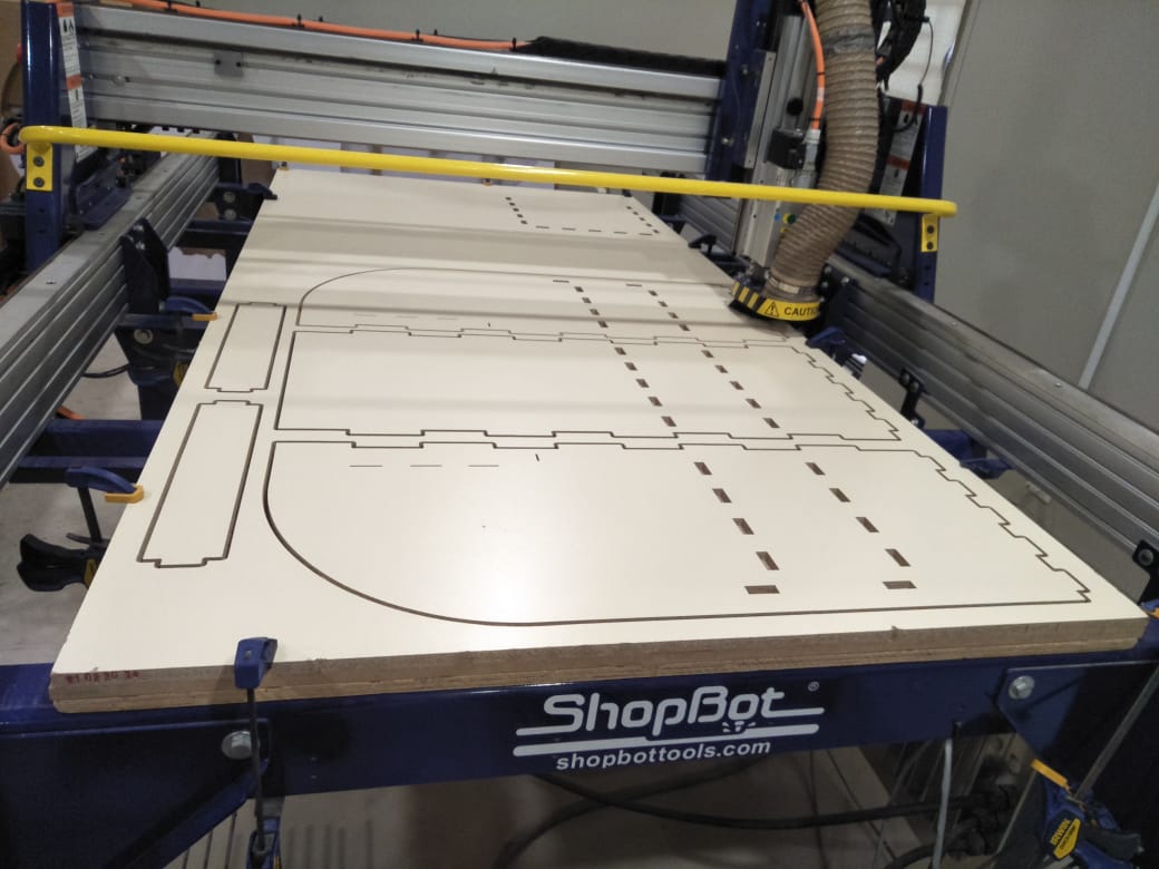
All parts are cut with different tool paths which I generated on vcarve.
ASSEMBLE THE PARTS
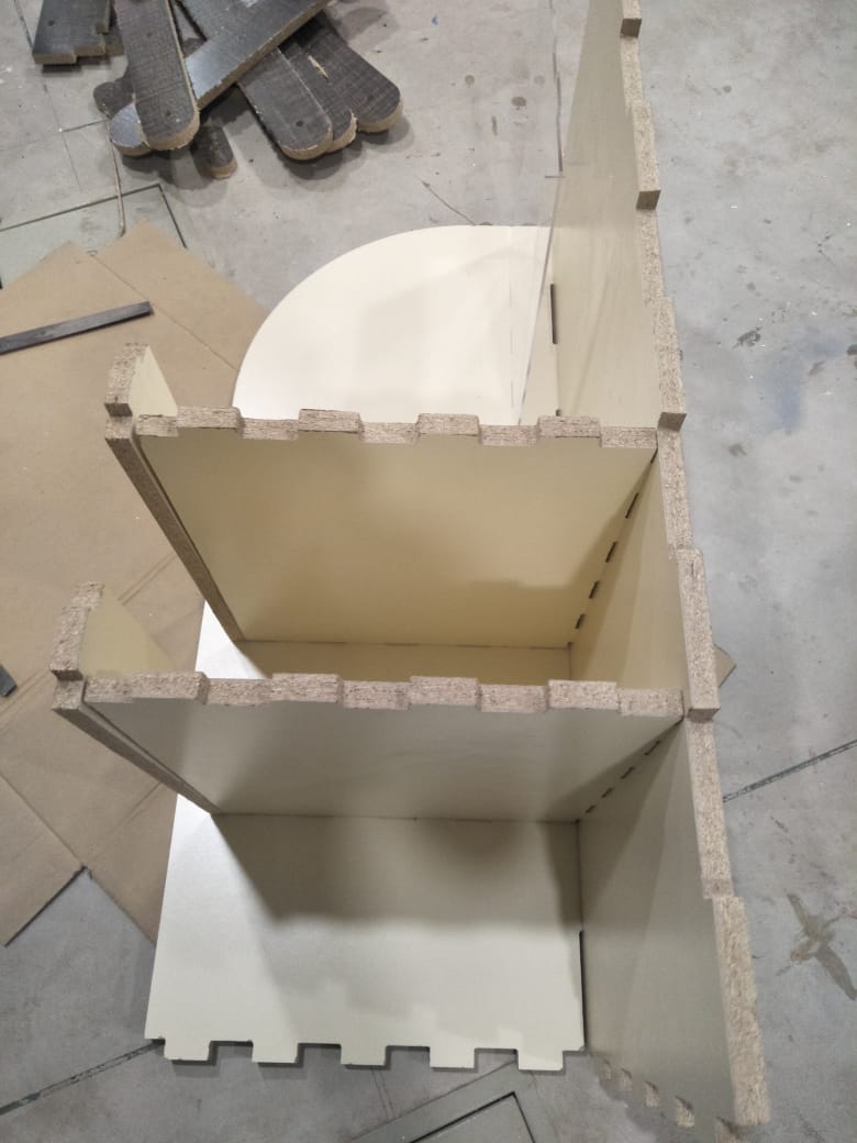
I started Assemble the parts they went easily, little bit get the help of rubber hammer.
FINAL RESULT
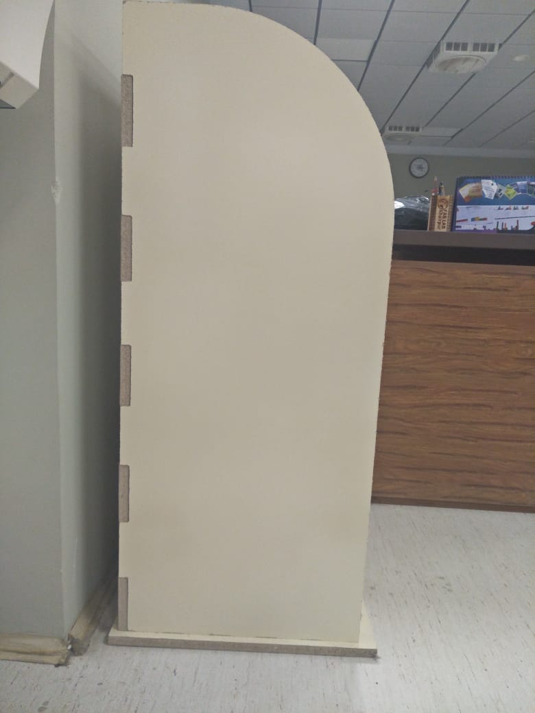
Perfectly Allign all parts and this is the side view of the News Paper Stand.
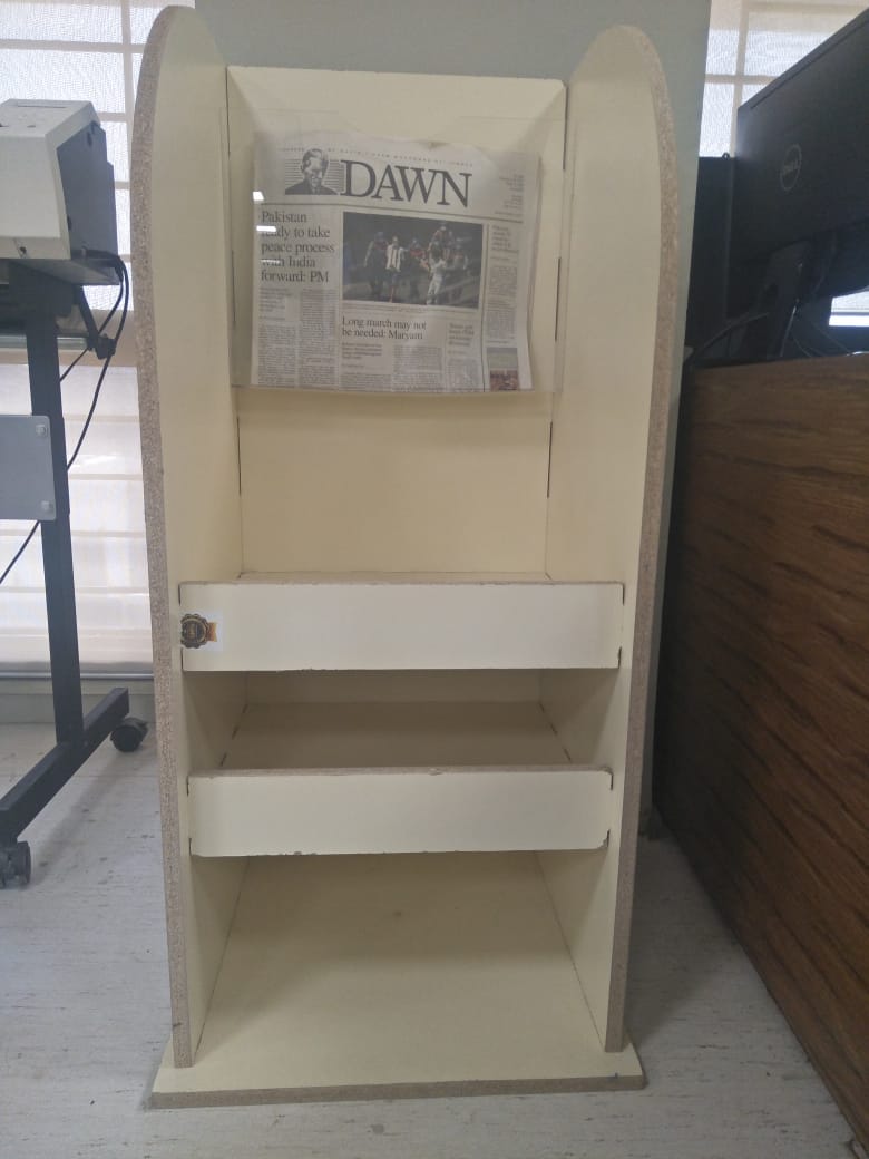
Front View after Assembling All parts to gather and news paper is also hanged in front side.
GROUP ASSIGNMENT
TEST RUNOUT,ALIGNMENT, SPEEDS, AND TOOLPARTHS FOR YOUR MACHINES.
For group Assignment we made a design in solid works and cut it in CNC.
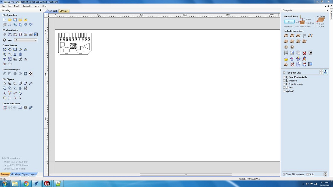
We save the file in a dxf format and open it in V carve pro to generate the tool paths.
AFTER CUTTING
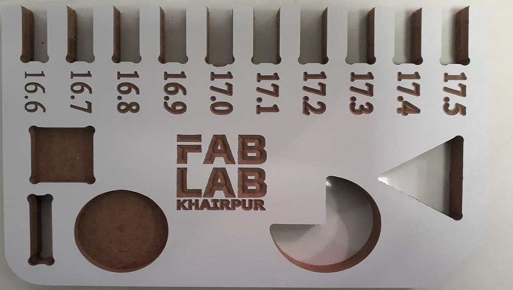
We have the MDF sheets in lab with thickness of 16.3mm. So we cutted part in that sheet, we used both outside cut and inside cut on different areas.
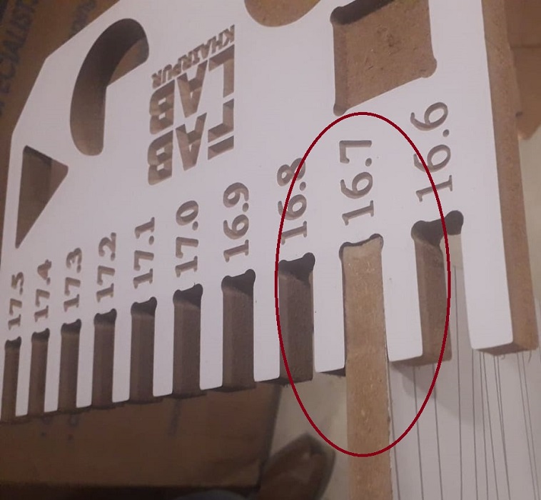
We also used pocket tool path you can also see in image and after cutting it was fixing in 16.7mm cutted area, we cutted this area with outside cut toolpath.
Propeller Led Pendulum Clock by Engr. Rashid Ali is licensed under Attribution-ShareAlike 4.0 International![]()
![]()
![]()