BACK TO HOME PAGE
WEEK 13
Embedded Networking and Communications
WEEK ASSIGNMENTS:
Tasks for a week
SPI COMMUNICATION:
What is SPI communication?
SPI is a common communication protocol used by many different devices. For example, SD card modules, RFID card reader modules, and 2.4 GHz wireless transmitter/receivers all use SPI to communicate with microcontrollers.
One unique benefit of SPI is the fact that data can be transferred without interruption. Any number of bits can be sent or received in a continuous stream. With I2C and UART, data is sent in packets, limited to a specific number of bits. Start and stop conditions define the beginning and end of each packet, so the data is interrupted during transmission. Devices communicating via SPI are in a master-slave relationship. The master is the controlling device (usually a microcontroller), while the slave (usually a sensor, display, or memory chip) takes instruction from the master. The simplest configuration of SPI is a single master, single slave system, but one master can control more than one slave

The clock signal synchronizes the output of data bits from the master to the sampling of bits by the slave. One bit of data is transferred in each clock cycle, so the speed of data transfer is determined by the frequency of the clock signal. SPI communication is always initiated by the master since the master configures and generates the clock signal.
Any communication protocol where devices share a clock signal is known as synchronous. SPI is a synchronous communication protocol. There are also asynchronous methods that don’t use a clock signal. For example, in UART communication, both sides are set to a pre-configured baud rate that dictates the speed and timing of data transmission.
Connections:

MOSI (Master Output/Slave Input) – Line for the master to send data to the slave.
MISO (Master Input/Slave Output)– Line for the slave to send data to the master.
SCLK (Clock)– Line for the clock signal.
SS/CS (Slave Select/Chip Select)– Line for the master to select which slave to send data to
Multiple slaves SPI:
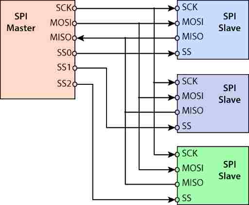
I connected the two Arduinos as shown in the image.
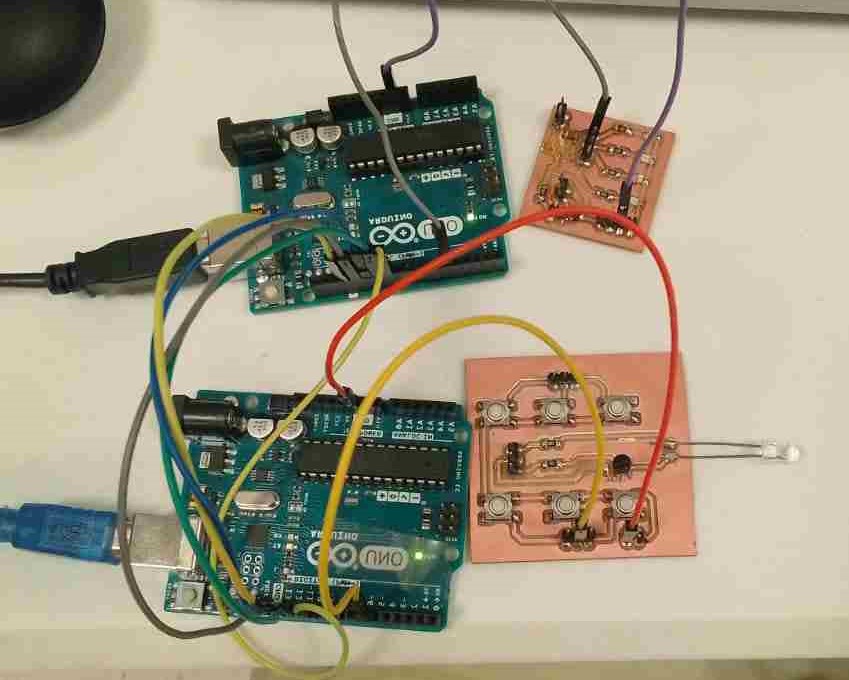
CODING:
Master code:
To begin, I make a sender program that sends a hello world message.

Slave code:
Then I create a receiver program to receive the master's message.
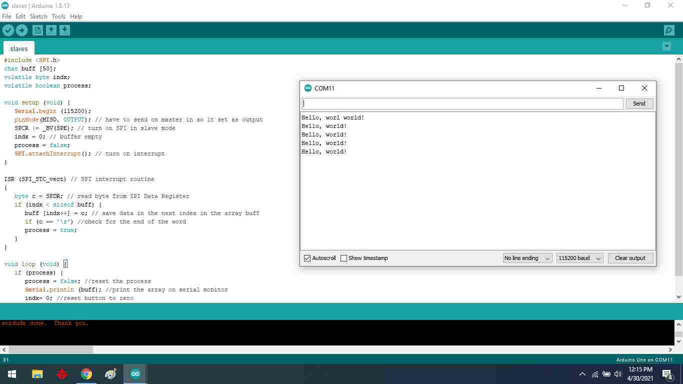
Master code:
To test that it was working fine I wanted to make a push button and LED program. I create a push button code in my master Arduino, and four LEDs light up in the receiver code.
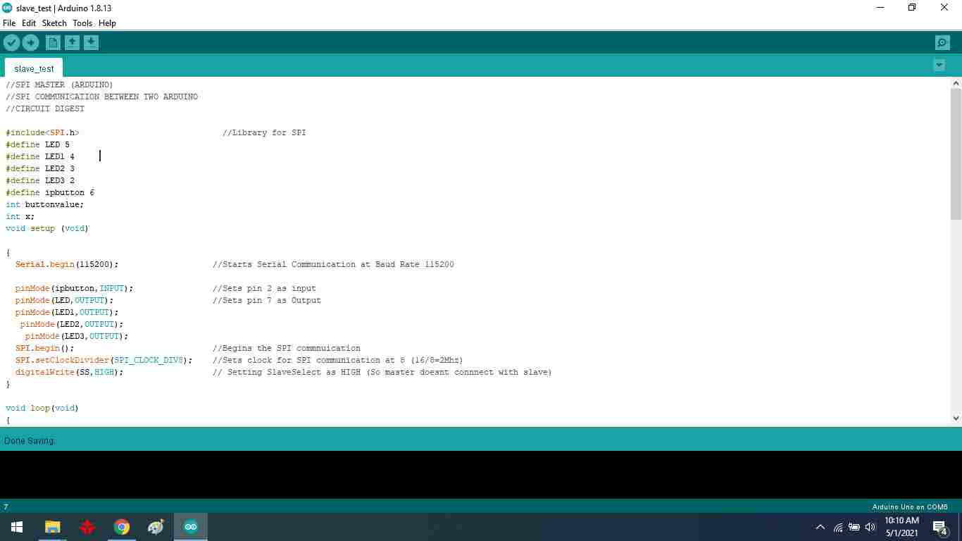
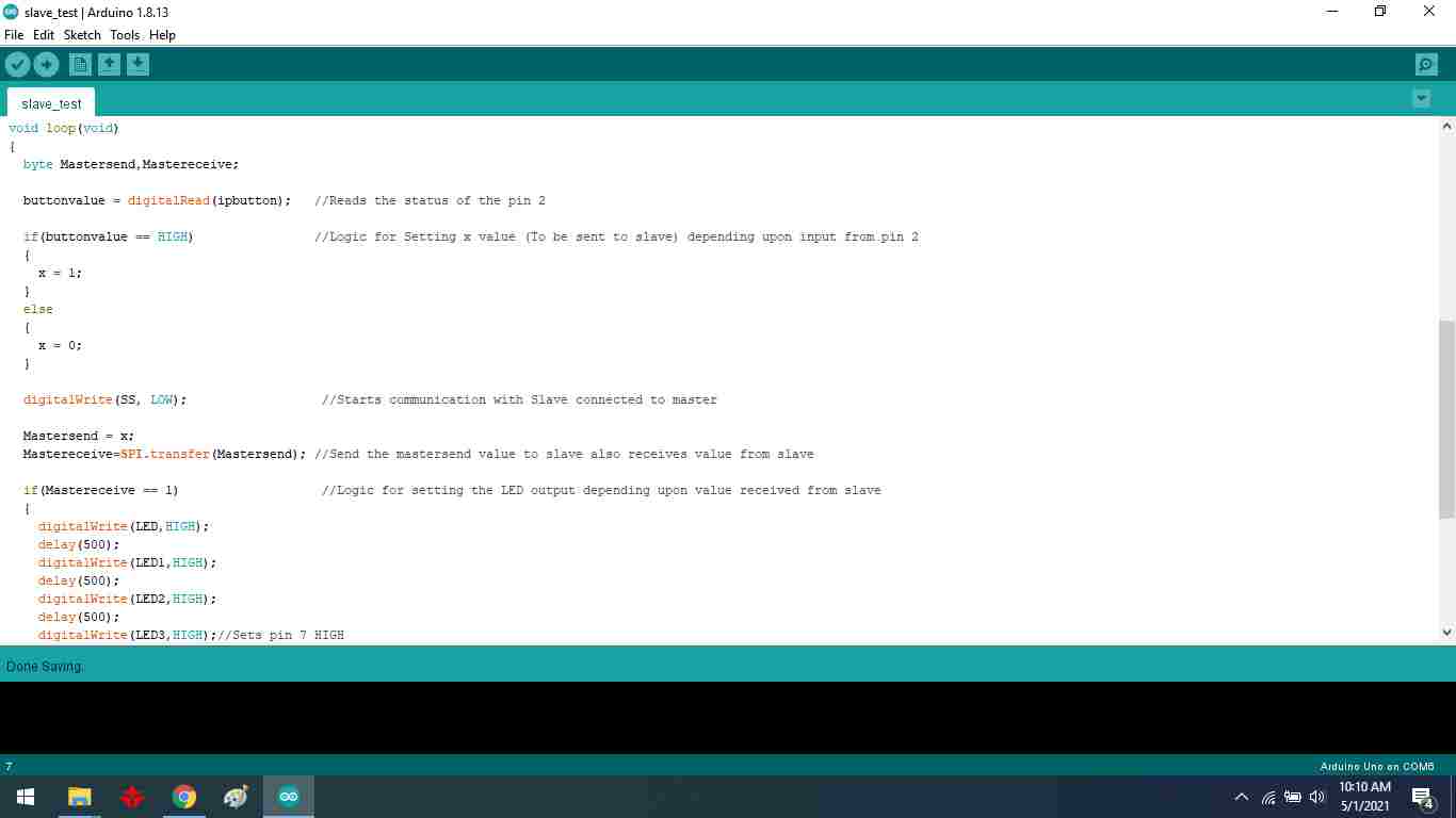
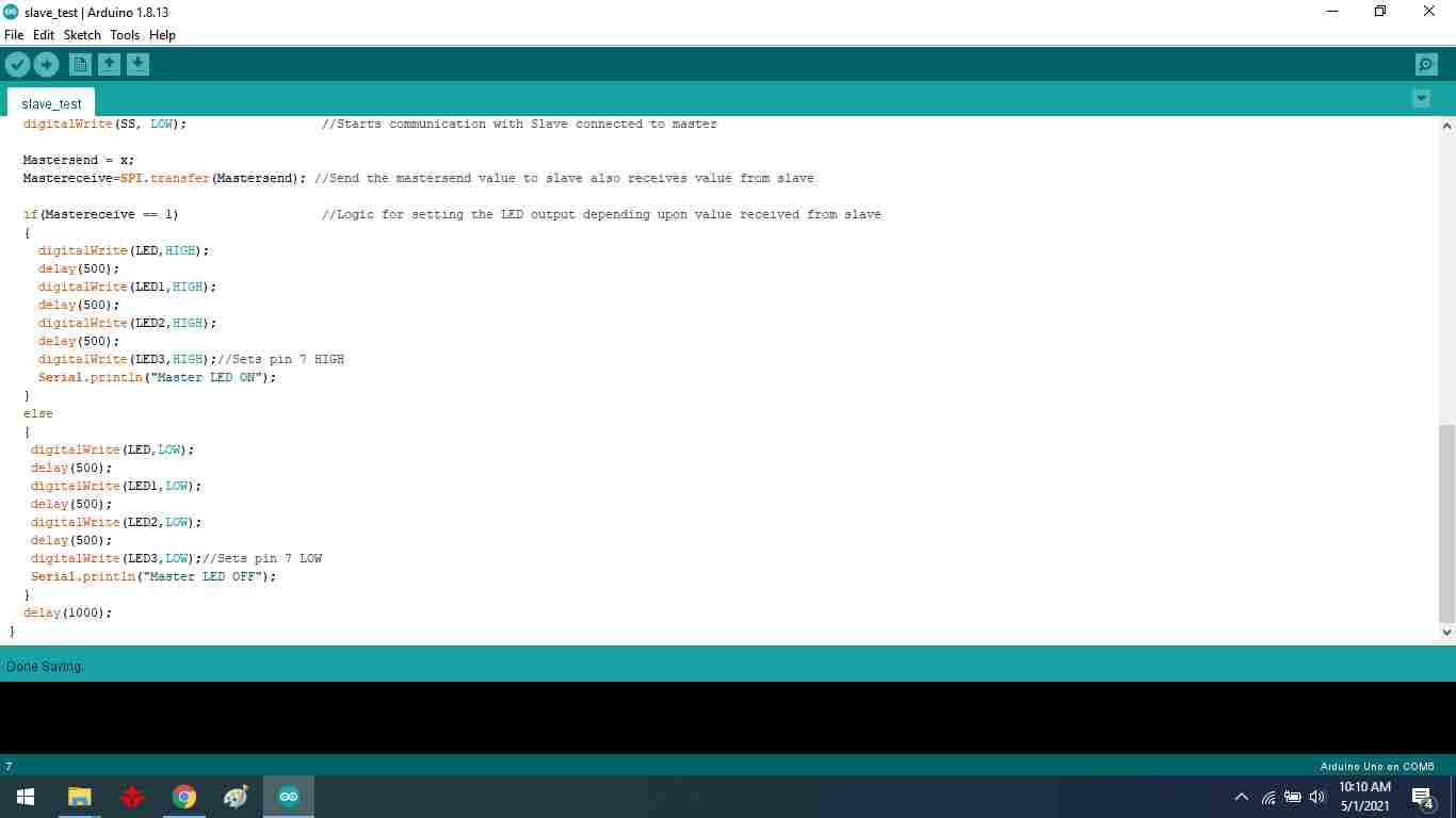
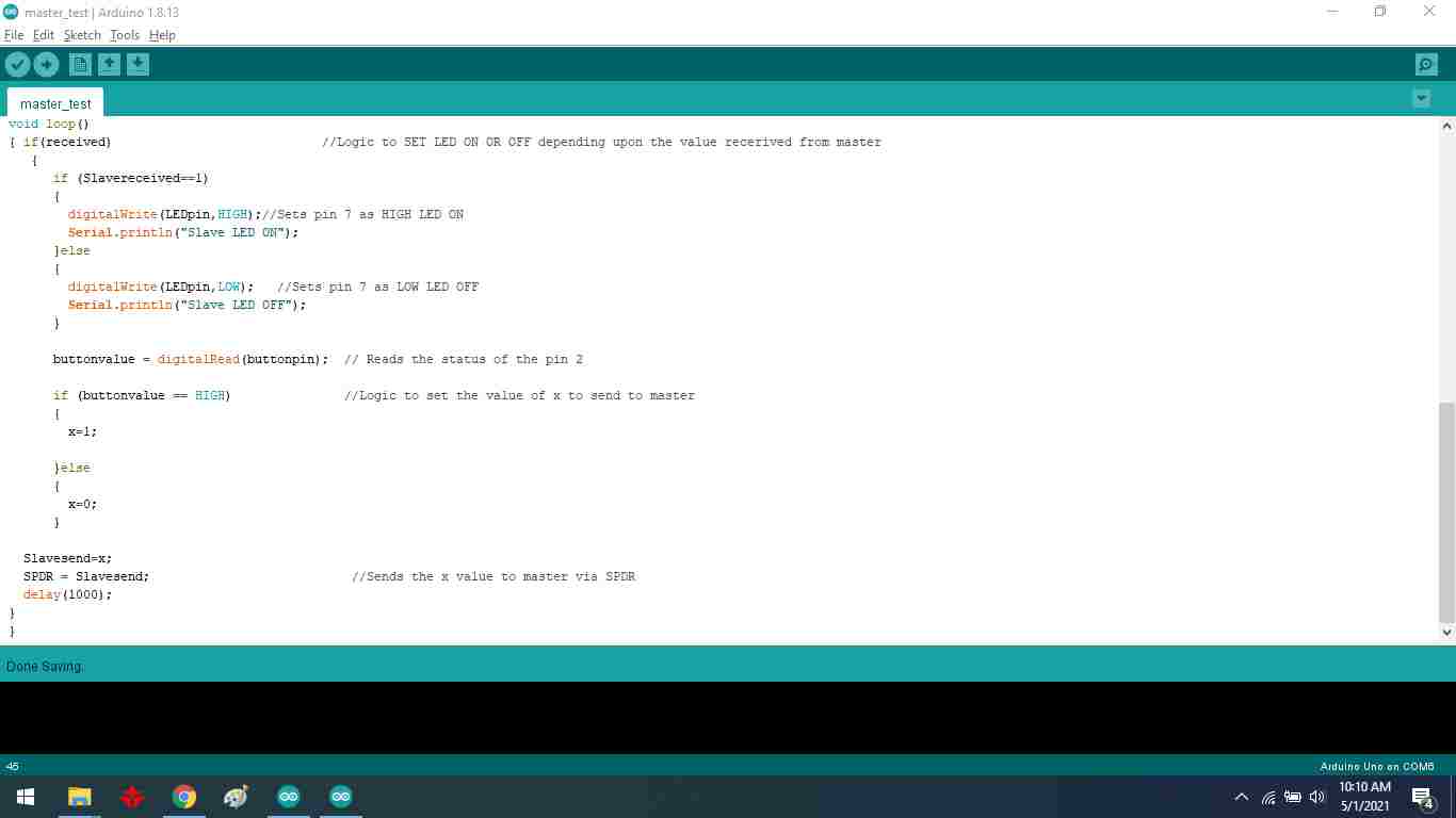
Receiver code:
Then I create a receiver program to receive the master's signal and light up the four LEDs.
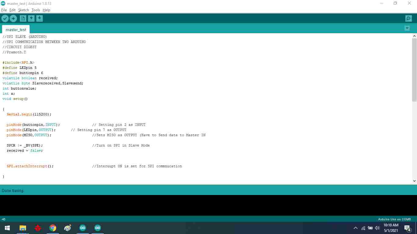
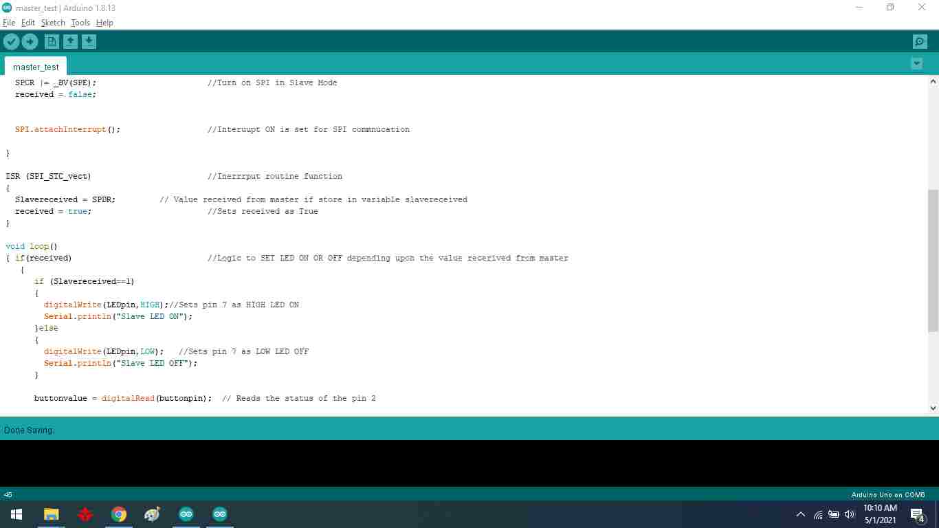
Testing code:
Test simple LED on breadboard.
Final Result:
Group Assignment
In this week, in group assignment we are working on the I2C communication between two microcontrollers, one is Arduino mega 2560, and the other is Leonardo Board. We have fellow this link to implement group assignments. HERE
What is I2C?
The I2C communication bus is very popular and broadly used by many electronic devices because it can be easily implemented in many electronic designs which require communication between a master and multiple slave devices or even multiple master devices. The easy implementations come with the fact that only two wires are required for communication between up to almost 128 (112) devices when using 7 bits addressing and up to almost 1024 (1008) devices when using 10 bits addressing.
Each I2C bus can support up to 112 devices. All devices need to share GND. The speed is around 100 kb/sec not very fast but still respectable and quite useable. It is possible to have more than one master on a bus, but it's really complicated and generally avoided. A lot of sensors use I2C to communicate, typically Inertial Measurement Units, barometers, temperature sensors, and some Sonars. Remember that I2C is not designed for long cable lengths. Depending on the cable type used, 2 m might already cause problems. Connecting more devices If we need to connect more than two devices on an I2C bus, we just have to connect all SDA and SCL lines together. We will need the address of every slave to be addressed from the master Arduino.
ADVANTAGES
DISADVANTAGES
We have connected micro controller, so these steps to connect two Arduinos using I2C:
First step Connect pin A4 and pin A5 on one Arduino to At mega 25600 pin 20 SDA , and pin 21 SCL . Second Step the GND line must be common for both Arduinos. Connect it with a jumper. Third Step Remember never to connect 5 V and 3.3 V Arduinos together. It won't hurt the 5V Arduino, but it will certainly annoy its 3.3 V.

This is the code of master and slave; that is used for the communication I have uploaded the code like master in mega2560 and Salve upload Leonardo.

To briefly go through the theory, I2C requires two digital lines: Serial Data Line (SDA) to transfer data and Serial Clock Line (SCL) to keep the clock. Each I2C connection can have one master and multiple slaves. A master can write to slaves and request the slaves to give data, but no slave can directly write to the master or to another slave. Every slave has a unique address on the bus, and the master needs to know the addresses of each slave it wants to access. Now let's go through the code.
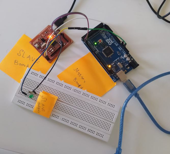
After the uploading the code in the respective board this is the result of our Group assignment in which master sent the command to the slave.bascialy in this assignment, we have considered one microcontroller board as a master board that will command on the other board that is a slave when I am going to press the button of the master board that will start blinking one time and sent the command to slave board for the blinking lED.even we have connected extra led on pin 13 for the blink that shows the communication between master and slave board.
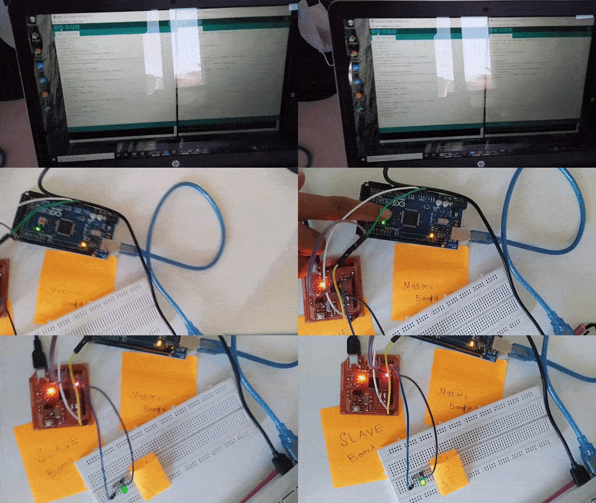
Final Result
"Click here"to download all files of this week