- Motor type: Brushed DC
- Operating Voltage: 12 VDC
- Load Speed: 300 RMP approx
- Rated Torque: 0.875 Nm
Week 12 - Output device
My final project is a mobile robot with 4 wheels that work using Omni Wheels, so the output devices I need are motors, in this case are 4 DC motors. But before doing anything it is necessary to determine the characteristics of the motor that suit the needs of the robot, because the robot is intended to support loads of approximately 20kg, it is necessary to determine the characteristics of the motor.
Determining the characteristics of the robot motor is something that can be done by hand using mathematical formulas, but for simplicity and to save time, I decided to use an online calculator to do the job for me, the calculator website is Oriental Motor .
Based on the required specifications, approximately 3.5 Nm is needed to move the entire body of the robot at maximum load capacity. Since there are 4 motors, each motor should have a torque of 0.875 Nm.
The necessary requirements are:
After a long search for motors based on specifications and price I found this motor that fits very well to what I need link, also includes encoder and gearbox.
At this point I already know the electrical characteristics of the motor I select, then it is time to start looking for the electronic components that will allow me to control the motor.
The electrical characteristics of the motor:
- Nominal voltage: 12 VDC
- Operating voltage: 6 to 18 VDC
- No load current: 200 mA
- Blocking current: 1.2 A
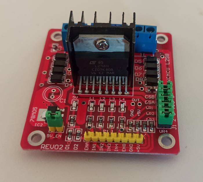
After taking a look at the motor controllers we had available we found that the L298N met these characteristics.
Maximum characteristic values of the L298N:
- Power Supply: 50 VDC
- Peak ouput current (per channel): 2 A
- Logic voltage: 7 VDC
There are many DC motor drivers available on the market, one of the most popular are the ones based on the L298N which allow to control two motors with a maximum current of 2A per channel.
To test the driver I decided to use my pcb which I personally call BIGtiny which uses an ATtiny 3216 controller and has all pins exposed.
Here a video of the operation.
The code loaded in the controller is as follows.
/*
* Motor Controller test program
* A test program to control the outputs of the L298N driver
*
* Author: Harley Lara
* Create: 01 May 2021
* License: (CC BY-SA 4.0) Attribution-ShareAlike 4.0 International
*
* This work may be reproduced, modified, distributed,
* performed, and displayed for any purpose, but must
* acknowledge this project. Copyright is retained and
* must be preserved. The work is provided as is; no
* warranty is provided, and users accept all liability.
*
*/

/* Motor Pins Configuration
*
* ATtiny3216 |  Fisical Pin | Prog  | Arduino | Function |
*            |       12     | PA2   |    9    |   IN1    | * Motor 1 Output 1
*            |       11     | PA1   |    8    |   IN2    | * Motor 1 Output 2
*            |       13     | PA3   |   10    |   IN3    | * Motor 2 Output 1
*            |        4     | PA6   |    2    |   IN4    | * Motor2 Output 2
*            |        2     | PA4   |    0    |  EN_A    | * Ena ble Motor 1
*            |        3     | PA5   |    1    |  EN_B    | * Enable Motor 2
*/

int motor1pin1 = 9;
int motor1pin2 = 8;

int motor2pin1 = 10;
int motor2pin2 = 2;

int en_A = 0;
int en_B = 1;

void setup() {

 pinMode(motor1pin1, OUTPUT);
 pinMode(motor1pin2, OUTPUT);
 pinMode(motor2pin1, OUTPUT);
 pinMode(motor2pin2, OUTPUT);

 pinMode(en_A, OUTPUT);
 pinMode(en_B, OUTPUT);
}

void loop() {

 // Speed Controll => 0 = off and 255 = max speed
 analogWrite(en_A, 100); // EN_A pin
 // analogWrite(en_B, 200); // EN_B pin

 digitalWrite(motor1pin1, LOW);
 digitalWrite(motor1pin2, HIGH);

 digitalWrite(motor2pin1, LOW);
 digitalWrite(motor2pin2, HIGH);
 delay(1000);

 digitalWrite(motor1pin1, HIGH);
 digitalWrite(motor1pin2, LOW);

 digitalWrite(motor2pin1, HIGH);
 digitalWrite(motor2pin2, LOW);
 delay(1000);
}
I started designing a motor controller based on the L298N driver and an ATtiny1614, my goal was that the microcontroller would be in charge of controlling the driver outputs. After some hours designing the schematic and the pcb routing everything was ready to machine.
Regarding the routing as the pcb had several connections it was impossible to connect all the components in a single layer, so I decided to make a two-sided pcb.
The schematic looks like this.
The final routing was as follows.
It was my first time making a two-sided pcb so the process of exporting the images for machining was done very carefully (I explain the process of how to do it later).
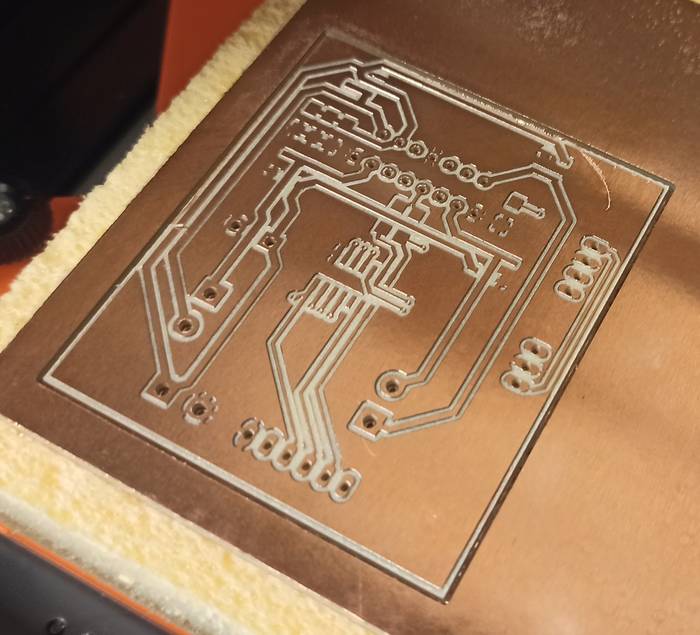
With the images ready and the gcode generated it was time to start machining the pcb, nothing special when placing the board, just make sure it was completely flat.
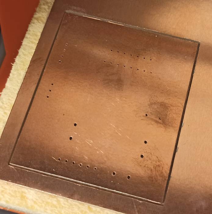
After a few minutes of machining this was the result.
While the pcb was being made I was watching many videos of different methods of making a two sided pcb (I know a little late knowing that the pcb was already in the machine), many recommended using reference pins to make sure that when I turned the board over it would be completely aligned but I didn't have reference pins so I discarded that method for now, some other people didn't use reference pins and just turned it over and aligned it with the sight, so I decided to try to do it this way.
I applied double sided tape over the surface I had just machined to hold it and machined the other side.
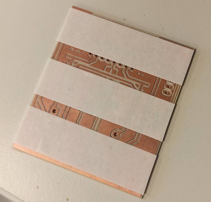
When I turned the pcb over I was very careful in the alignment, I used the margins of the outer cut as a reference, it was just a matter of making sure they were all the same size.
The result had a deviation of less than a millimeter, nothing serious, I made sure there was nothing strange in the result and everything seemed to be fine.
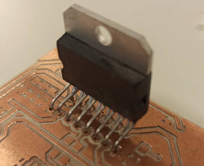
I tested how the driver looked on both sides and this was the result.
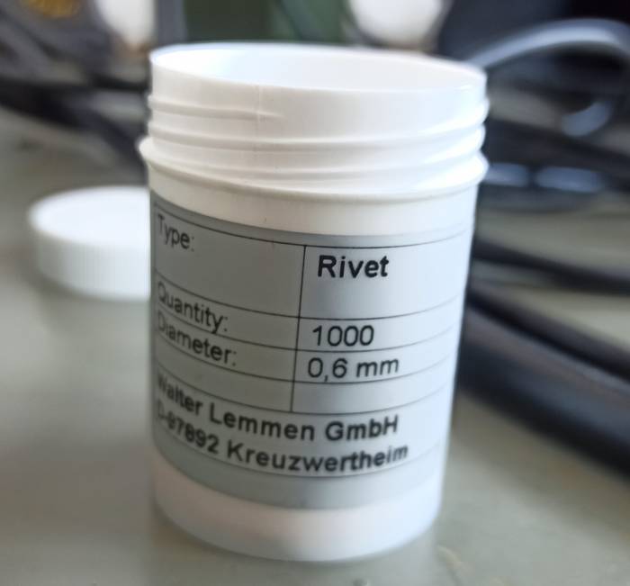
Now it was time to add the rivets that would connect the top side traces to the bottom side traces. In the lab I had available the 0.6mm diameter rivets, just the size I used in the KiCad design.
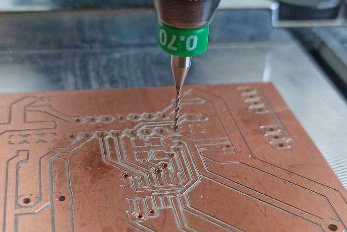
Although the holes for the rivets were 0.6mm in diameter it was necessary to make them a little bigger, this time I used a 0.7mm drill bit and carefully made all the holes a little bigger.
Luckily in the lab there was also the tool to place them so it was just a matter of putting the rivets on top.
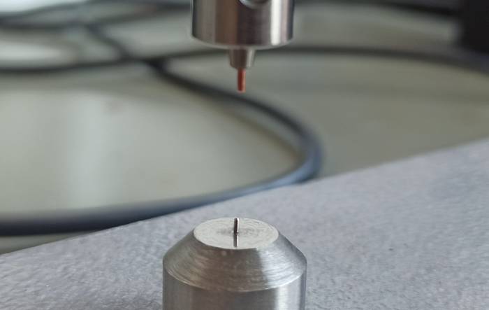
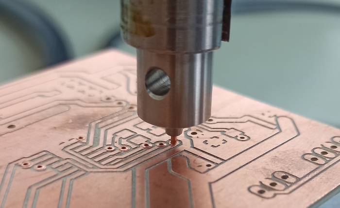
I placed the pcb and carefully lowered the rivet making sure it was aligned in the hole, once aligned I applied a little pressure and that took care of holding the rivet in place.
I then soldered all the components and checked with the multimeter that all the connections were correct.
Curiously the controller did not work!
I contacted my instructor (Daniele) commenting that the pcb was not working so he kindly traveled to the city where I was to help me check what was going on.
After many hours of unsuccessfully testing many things we did not understand what was wrong and why it was not working, until at one point testing a connection with the multimeter there was a short circuit and the ATtiny in the pcb died, it was a little late so Daniele had to leave and I had to find a solution.
Since the ATtiny was dead and the pcb didn't work and we didn't know why my solution was to design from scratch a completely new board.
You can find a complete tutorial on how to make the pcb from scratch at this page
I decided to start completely from scratch and add some features that I think would be useful like a voltage regulator integrated in the pcb that could be enabled and disabled as well as the possibility to use an external controller instead of using the integrated ATtiny1614 (this in case the ATtiny1614 died again).
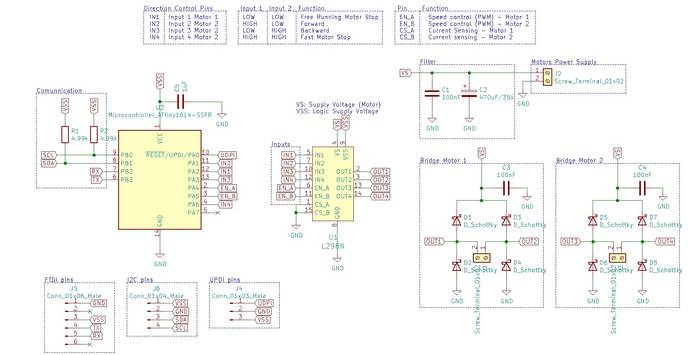
After working on creating the schematic this was the result.
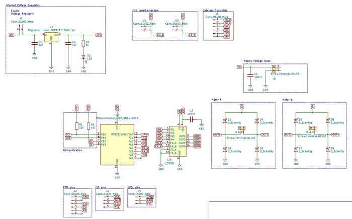
The schematic seemed to be all right, I checked it several times to make sure it was working properly.
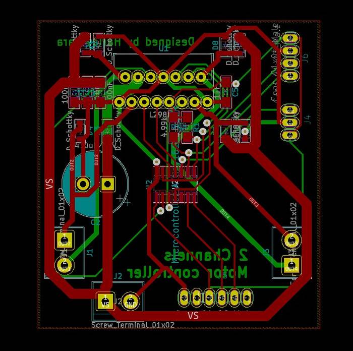
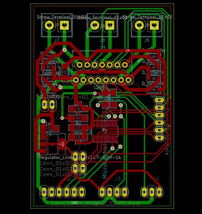
Now it was time for routing and I had more components than before so I arranged everything in a completely different way than the previous version, so that all the pins and connection ports were more accessible and away from the driver outputs.
This was the result after a long time of routing.
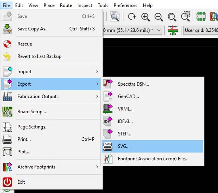
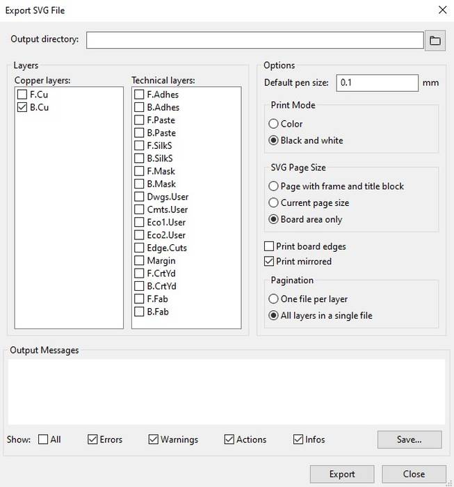
For the machining it was necessary to export both sides of the pcb, the process is quite simple.
In the upper left corner under File->Export->SVG
That will open a box in which you have to check only what you want to export, in this case I wanted to export only the top layer and the border.
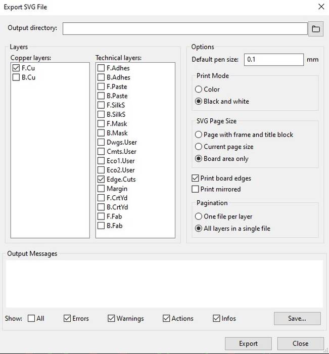
And to export the lower part I was only interested in exporting the traces, but it was important to check the option Print mirrored.
With the files ready to be processed I took them to FabModules and generated the code to machine them.
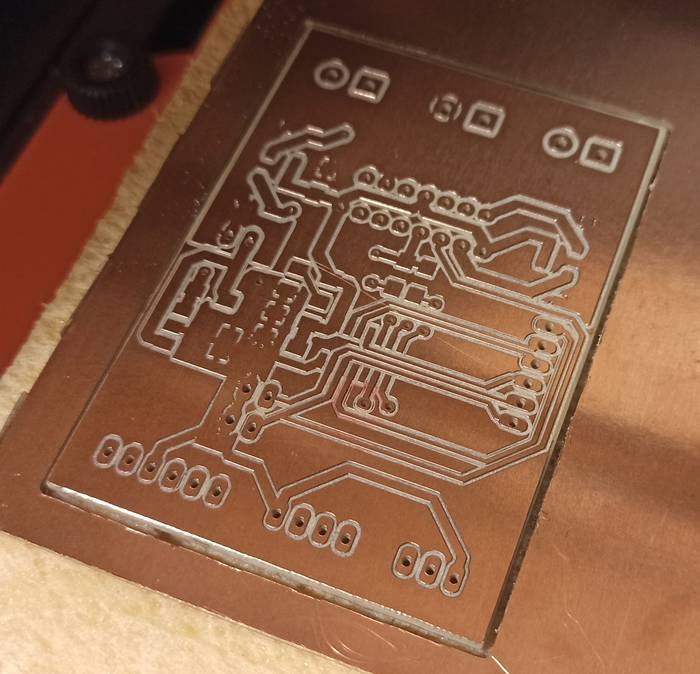
The procedure was the same as the previous attempt, after the first side was ready it was a matter of carefully turning the pcb over.
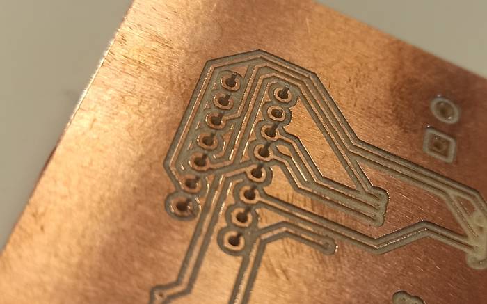
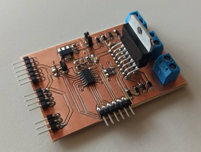
The top pcb turned out like this.
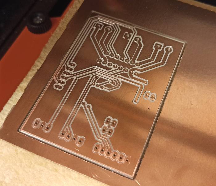
And the lower part like this.
I soldered all the SMD components.
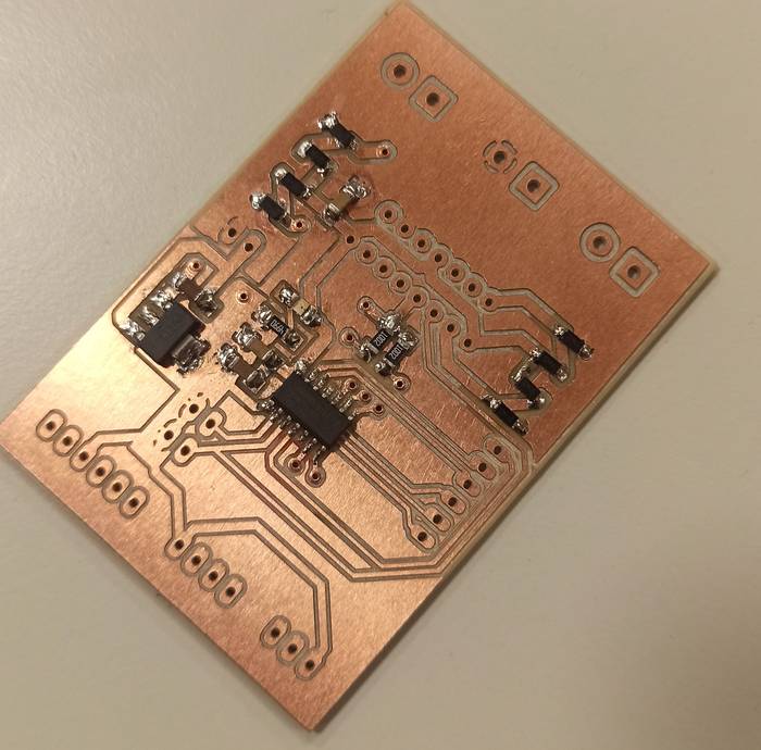
And finally the headers and connectors.
Finally I tested with the multimeter all the connections and they seemed to be ok.
Now it was time to connect it and test if it worked, to do this I loaded the same code from the "Testing an existing driver" section in the ATtiny1614 integrated in the pcb, the program was uploaded to the board without problems.
But at the moment of activating the 12V source nothing happened, the motor did not move, I thought that the control signals from the ATtiny1614 to the Driver were not well and I checked them with the multimeter and the oscilloscope and indeed they were fine.
At this point I felt pretty tired and did not understand why it was not working, so I asked my partner Jefferson Sandoval to help me if he could check the PCB. After a while reviewing the code that was loaded on the microcontroller and the connections based on the schematic he found that the 5V logic connection that the driver uses to interpret the control signals was not arriving because the rivet that brought the 5V signal from the bottom to the top was not making contact with the board, the solution was to apply a little solder and after that it worked wonderfully.
The group assignment is to determine the power consumption of an output device, in my case for the final project I will be using DC motors so I am going to determine the power consumption of a DC motor.
The motor I am using is this one, and it has the following specifications:
- Gear Ratio: 107.15:1
- Max power: 2.2 W
- No-load speed @ 12V: 130 rpm
- No-load current @ 12 V: 0.08 A
- Stall Current @ 12 V: 1.6 A
- Torque hutch @ 12V: 6.5 kg.cm (90 oz.in)
These values are the values provided by the manufacturer which I am going to compare with the values measured by me.
To make the tests I connected the motor to a DC power supply at 12V, when activating the output of the power supply the motor starts to rotate at a constant speed, but if the voltage is decreased the rotation speed decreases, in the opposite case if the voltage is increased the speed increases. The demonstration is in the following video.
It can be seen that the motor without any load uses a current of 0.033A at 12V. To determine the consumption we apply the formula Power = Voltage * Amps replacing the terms we obtain Power = 12 * 0.033 = 0.396 Watt.
Based on the motor specifications it can be seen that the current consumption of the unloaded motor is lower in the measurements, and that the energy consumption (of course) is lower than the maximum.
Group assignment page- Arduino 1.8.13
Fab Motor Controller - Tutorial step by step
Fab Motor Controller - KiCad Project
PCB images for milling
Gcode for Roland SRM-20