Week 11 - Molding and casting

3D Modeling in Fusion 360

For this assignment my plan was to design a roller to be used in the mecanum wheels that I plan to use for my final project.

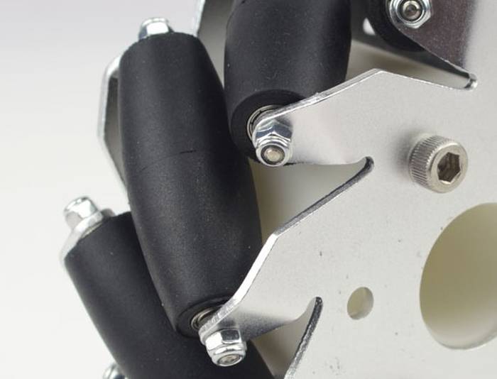
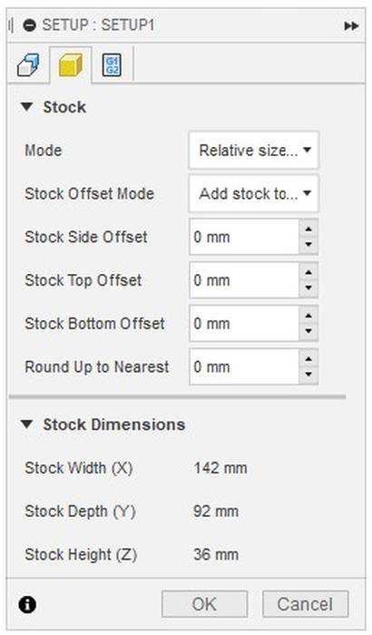
The process starts with the 3D design of the mold, the first thing was to measure the dimensions of the wax available in the lab. In this case the block of wax available is 142x92x36 mm, from these measures I created a cube in which I removed a space in which I placed the 3D model of the rollers, then was simply add some reference pins that will be useful for the casting process and ready.

A very important note is that the model must be perfectly mirror the other, otherwise it will not fit.

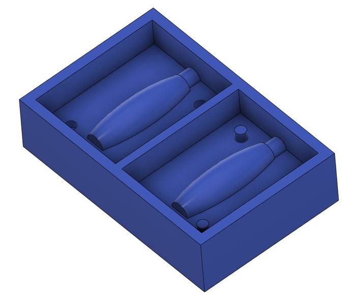
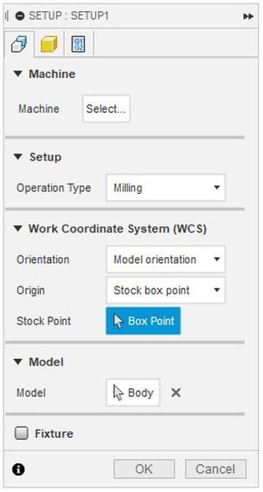
With the 3D model ready now it is time to go to the Fusion 360 workspace called "Manufacture", in that place the first thing is to create a SETUP where it is important to define the coordinates of the machine which must match the coordinates of the machine to be used in the milling process.

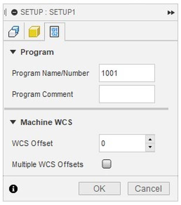
The SETUP configurations are as follows.


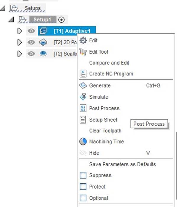
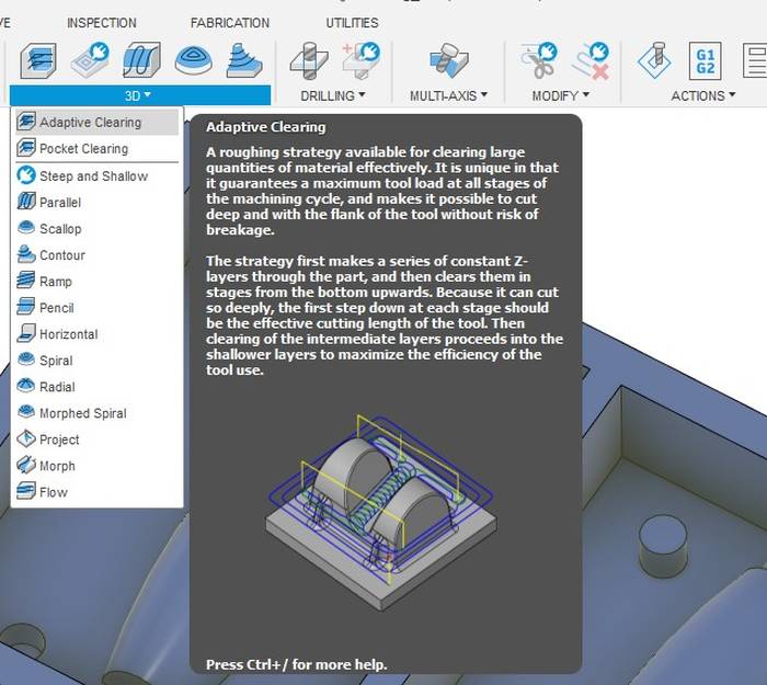
The next step was to use "Adaptive Clearing" as the first pass to remove the first layer of material.

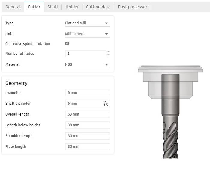
The tool to be selected to do the job should have the same dimensions and characteristics as the actual tool, so it is good practice to measure the actual tool and fill in the values as seen in the following image.

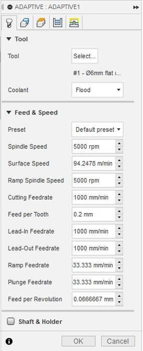
The speed settings are shown as follows.

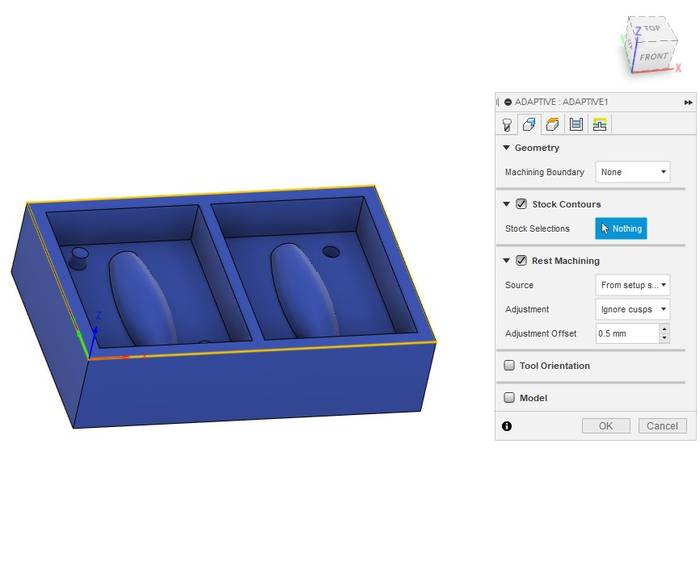
In the "Geometry" tab the settings are as follows.

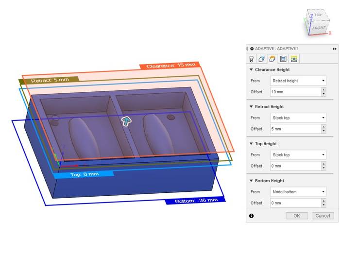
In the "Heights" tab the retraction, clearence, top and bottom distances are as follows.

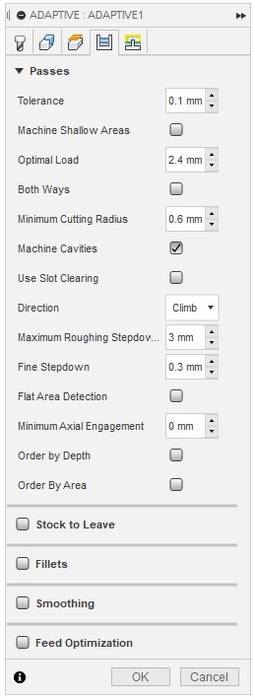
In the "Passes" tab one of the most important parameter is "Fine Stepdown" which defines the height between each pass which the lesser some the final result will have more resolution but will take much more time.

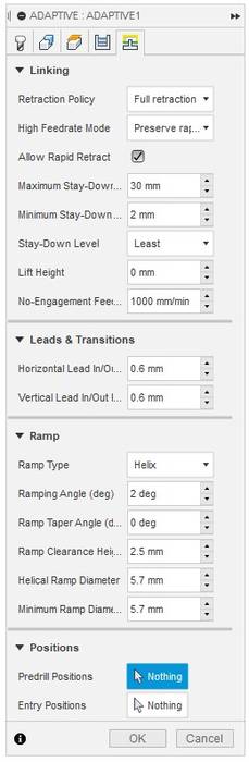
The last tab "Linking" remains exactly the same.

The result of all the paths for this task looks like this.

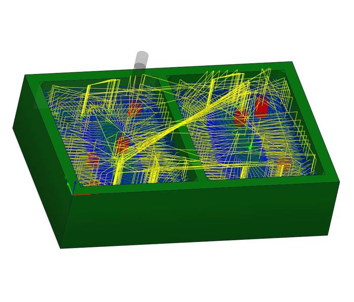
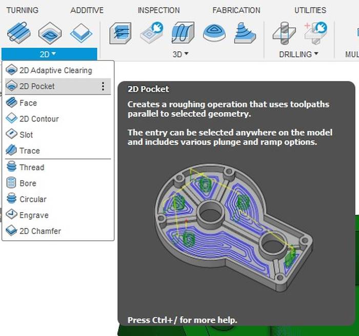
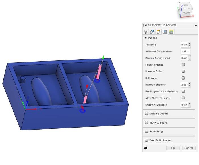
As you can see in the previous image the registration holes were not made so it is necessary to do another task to make them. In this case use 2D Pocket to make the registration holes.

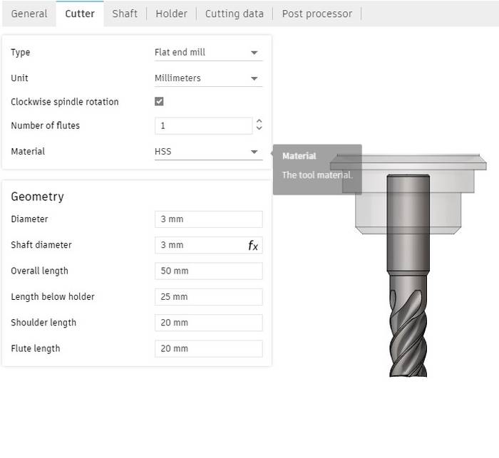
To make these holes I used a smaller tool than the previous one, that tool had the following characteristics.

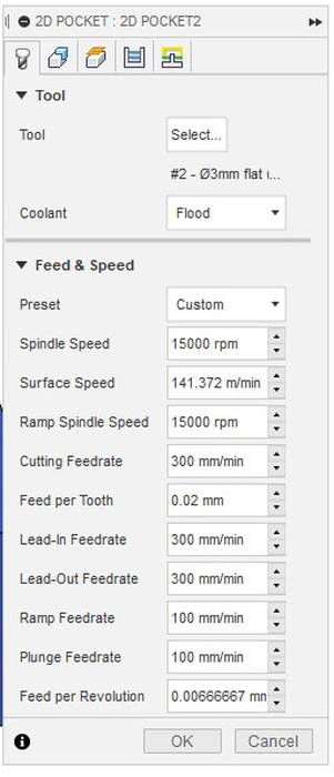
In the "Tool" tab the speed settings look like this.

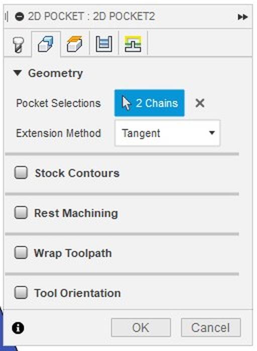
In the "Geometry" tab is necessary to select the geometries that we want to machine, in this case are the log holes to select it is a matter of clicking on the bottom edge of the hole, that highlights the selected geometry and red arrows appear that if they are inside the geometry means that the inside will be milled and if they are outside means that the outside will be milled.

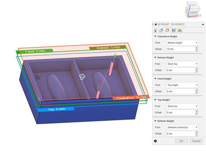
In the third tab "Heights" the tool operating distance is defined, in this case the default values are shown.

The next tab "Passes" does not need such a low Stepover as it is only with holes.

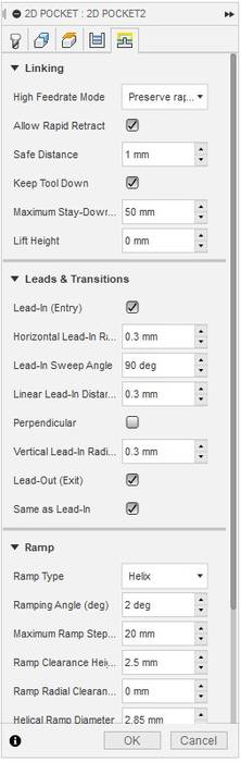
And the last tab "Linkings" looks like this.

At this point the mold already has the basic shape of the roller and the registration pins for the casting. The next step is to make a finer pass that is normally used for the final finish, this last pass can be done in many ways and with different tools, one of the best is to use a Ball End Mill, but this time I only had available a Flat End Mill, the one I used for the "Adaptative Clearing" which is 6mm diameter and a 3mm diameter for the holes, so I used the 3mm for the final finish.

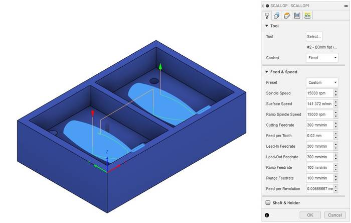
Of all the possible tasks, one of the best final results was "Scallop", that's why I decided to use it as the final finish.

The tool selected is the same as the one used in the previous task, it is a Flat End Mill of 3mm diameter.

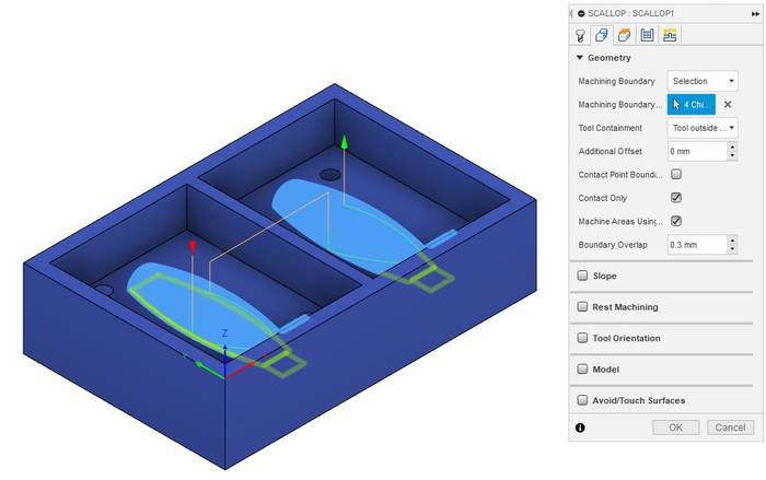
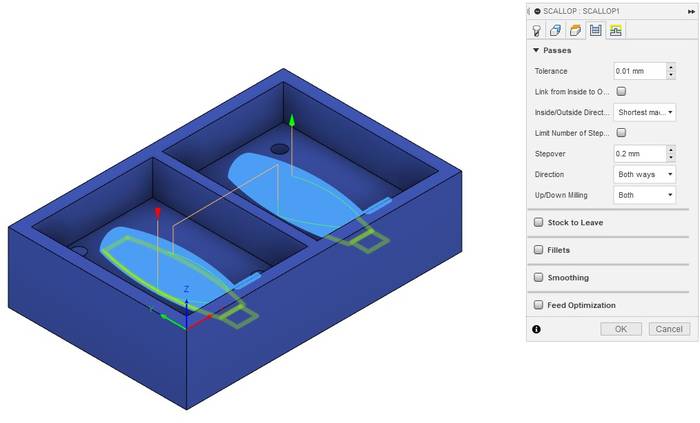
In the second "Geometry" tab it is necessary to select the lower part of the geometry to be milled as shown in the following image.

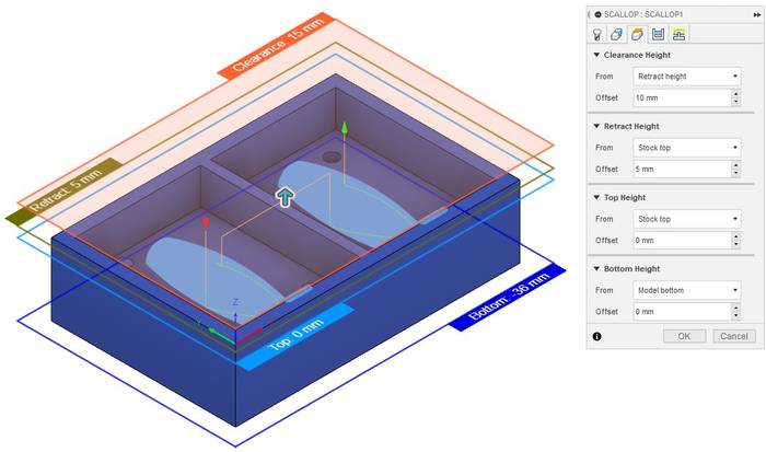
In the "Heights" tab are the default values.

In the "Passes" tab the most important parameter is the "Stepover" because it is the final finishing pass must be a fairly low value, in this case the value I am using is 0.2mm.

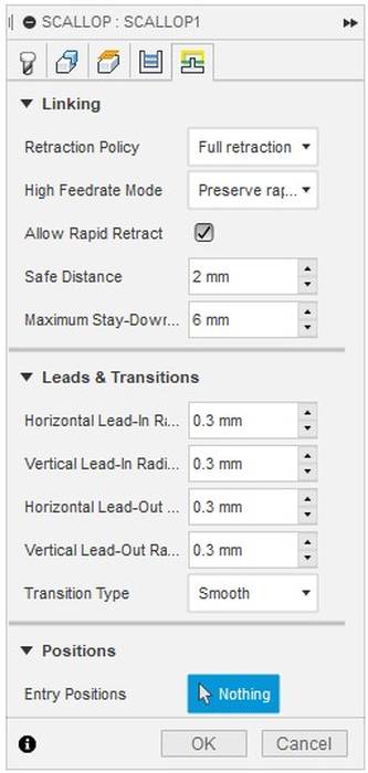
In the last tab "Linkings" everything is kept with the default values.

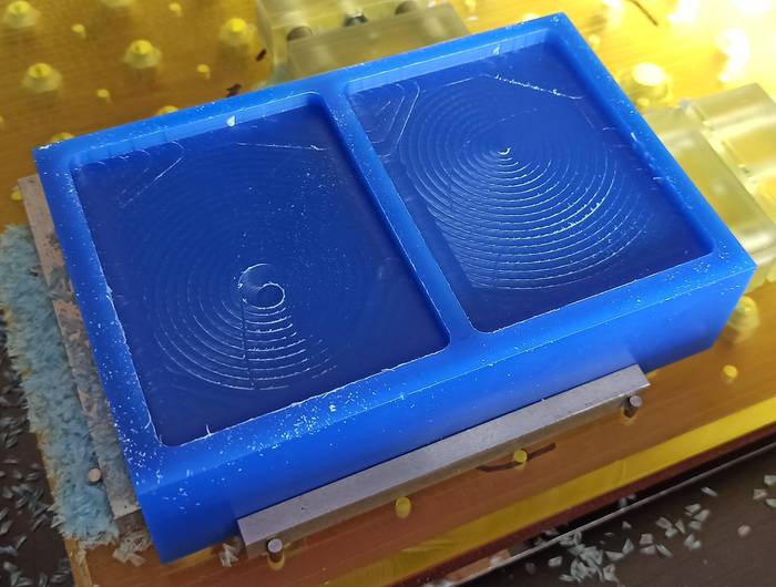
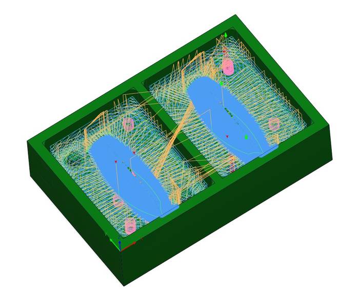
The final result of all the milling jobs look the way they do inside Fusion.

Before exporting any file it is necessary to make sure by means of the simulation that all the milling jobs are being done as intended, it is necessary to verify that there is no collision during the process and if it is possible to optimize a little the pressing time.

Exporting files for milling

The process of exporting the milling files is quite easy, in this case as I have 3 jobs one of them with the Flat End Mill and two with the 3mm I am going to export two jobs, one for the "Adaptive Clearing" and one for "2D Pocket" and "Scallop".

To export the milling file you need to right click on the job and then click on "Post Process".

This action will open a window where you need to select the file save address and the machine for which you want to export the file, in this case I used a Roland MDX-40 so I selected the processor "Roland RML / roland rml" and in the properties section the machine type "MDX-40".

The process of exporting the file to use the 3mm tool is exactly the same, you only need to select both milling tasks and the rest of the process is the same as above.

Milling process

This section describes the milling process for the mold using a Roland MDX-40.

The first thing is to place the wax block in the work area of the machine, it is important to secure the block using any method of clamping that does not interfere with the tool path, in this case I am using pins and some amazing clamping parts thanks to Ferdi's work designing this useful bed for the MDX-40.

The next thing is to adjust the Z height, for the MDX-40 machine I am using the sensor that the machine has available. To make use of the sensor it is a matter of placing it on the bottom of the tool as shown below.

Then in the VPanel control software, in the Set Origin Point section I have checked the option "Set Z origin using sensor" and then click on the "Detect" button, this causes the tool to start to slowly descend until it makes contact with the sensor.

With Z set now it is time to set the origin of the wax block, it is important to remember that in Fusion 360 when we create the "Setup" we select an origin point, the XYZ origin point that we use in the machine must match that origin in Fusion 360.

Due to the schedule in which the milling process was going to start it was necessary to leave the machine working during the night, then for security if something went wrong or any process was not performed I recorded the coordinates of the machine, which are absolute coordinates that means that they are always the same regardless of the work to be done or any other situation.

After a few minutes of running the Adaptive Clearing job the MDX-40 has a VIEW button which pauses the current job and allows you to open the machine and check that everything is going according to plan.

A few minutes later the Adaptive Clearing job was finished with the following result.

Next was to change the tool for the 3mm Flat End Mill and run the 2D Pocket and Scallop work, I made sure everything started well and left the FabLab because it was late enough to close, but the machine would stay working.

After the weekend early in the morning I arrived at the FabLab to see the result which is as follows.

The holes for the reference pins and the basic shape of the roller was very good, but for some reason the last pass that would give the final finish was not done, but that was not a problem because the final piece is a roller that does not necessarily have to have a smooth surface on the contrary this result brings more friction to be in contact with the ground.

Silicone preparation

For the casting process the materials I used were "ProtoSil RTV 245 Komp. A" and "ProtoSil RTV 245 Komp. B1".

Before starting it is necessary to clean and remove any kind of dirt in the mold to make sure that when the silicone is deposited there will not be any kind of particle. For the cleaning process I used compressed air.

The next step was to deposit component A in a special plastic casting container because other plastic containers can react to the components of the mixture and spoil them or become dangerous to the point of melting the plastic container.

According to the ProtoSil RTV 245 datasheet the mixing ratio of component A and B is 100:10.

It is important to clean properly after use to ensure that the cap does not stick to the bottle in the future.

According to the datasheet the curing and mixing process is recommended to be done in vacuum, it is important to clean the mixing tool after use so that the next person who needs it will find it clean and ready to be used, unfortunately we found the mixing tool completely dirty and it was necessary to remove the remains so that they do not affect our mixture.

With everything ready in the vacuum machine we proceed to turn on the vacuum and we see how the pressure begins to drop, it is necessary to be careful not to spill any of the components so if we see that the bubbles are rising too much we can release the pressure a little.

After some time in vacuum to expel the air from the components, the mixing tool is placed and component B1 is carefully poured into component A.

These levers on the side of the machine are used to control the deposition process of component B1 on component A.

With the component mixture and without removing the tool to avoid generating bubbles, it is carefully poured with a thin silicone line into the mold.

With the mold filled we will see that some bubbles arise from the silicone which is normal and now it is a matter of waiting for it to be ready.

The result after the silicone is as follows.

It looks very good and contains no bubbles. Now it's just a matter of preparing the mold for casting.

Resin preparation for casting

For the casting process the components will be "NEUKADUR ProtoCast 105 comp. A" and "NEUKADUR ProtoCast 105 comp. B".

According to the datasheet of both components the mixing ratio of the components should be 100:200 (comp. A: comp. B). Therefore component B corresponds to 157g.

For component A it corresponds to 78.5g.

The next step was to place component A in the vacuum machine to remove the air.

Then both components were mixed and this must be done quickly because both components react in 3 min and with care not to generate bubbles in the mixture.

We put the mixture in the mold.

And after several hours of waiting this is the final result.

Group Assignment

This section review the safety data sheets for each of your molding and casting materials

For ProtoSil RTV 245 silicone it is recommended to keep the material closed in the original container at a temperature of 15 to 25 degrees Celsius. Based on the datasheet the first two numbers on the label correspond to the number of months and the third to the number of years the product can be stored as long as it is kept under the previous indications.

The table describing the mixing data is as follows

For the NEUKADUR ProtoCast 105 material it is recommended to keep closed in its original container at a temperature between 20-25 degrees Celsius, as well as the previous one, the digits on the label mean that it can be stored for 5 years and 10 months as long as the storage recommendations are complied with.

The table describing the mixing data is as follows

For both materials it is recommended to work in an area with good air circulation, wear gloves and in the case of NEUKADUR ProtoCast 105 resin it is also necessary to wear a mask. In both cases, care must be taken with the container used to make the mixture or to deposit the material since the plastic of these can react with the components and can even melt, therefore it is recommended to use containers that were designed for molding and casting.

Group Assignment Page
Softwares
Machines
  • Roland MDX-40
  • Schüchl UHG-500 Easy
Datasheets
Files
Molding box for the roller - Fusion file