After using Fusion 360 for some years for 3D modeling I decided to experiment a little
more with other forms of 3D modeling, some time ago I used a software called OpenSCAD
to model a piece of which I needed a function to describe its surface to use it in a
robotics project, then I wanted to use it again to model some figures based on mathematical functions,
but I haven't used OpenSCAD for a long time so I needed to refresh a little the syntax,
for that I started modeling something very simple and I was scaling in levels until I got to model something interesting.
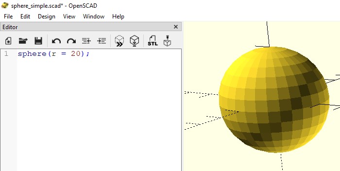
Level 1
In level one I decided to make something very simple like a sphere, OpenSCAD already has
some primitive shapes so it was as easy as making this little code.
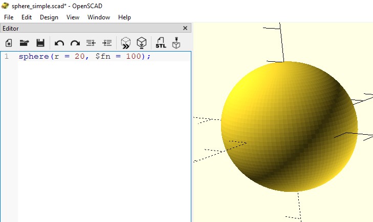
It looks good but can still be improved by smoothing the surface by adding more divisions.
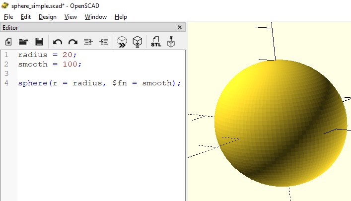
Finally, to make it easier to edit (although it is already quite simple) we only need to add variables.
Level 2
For this level I decided to increase the level of difficulty, I proposed to model a sphere but represented in a geometry like Wireframe.
In this case it was necessary to use the parametric function that defines a sphere, the result looks very nice.
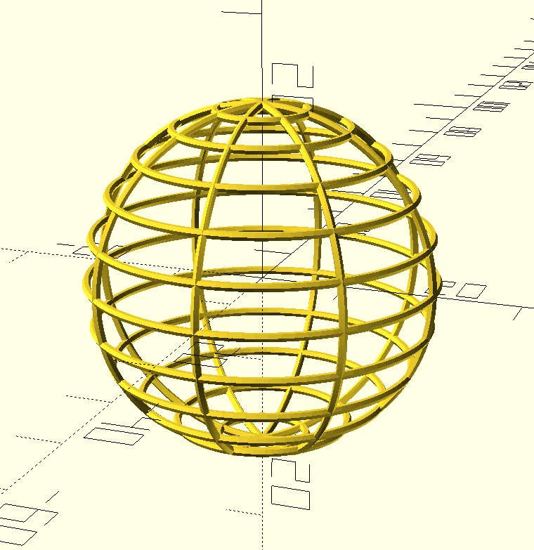
The code is much more extensive than the previous one.
                              ////////////////////////////////////////
                              // VARIABLES

                              radius = 20; // sphere radius
                              pi = 3.14159; // pi ¯\_(ツ)_/¯
                              theta = 0;
                              alpha = 0;

                              // 3D line parameters
                              smooth = 5; // line smoothing - WARNING: increasing this value too much causes the compilation to take a long time.
                              line_w = 0.5; // line width

                              // Sphere position
                              x0 = 0;
                              y0 = 0;
                              z0 = 0;

                              h_n = 8; // horizontal lines
                              v_n = 12; // vertical lines

                              ////////////////////////////////////////
                              // FUNCTIONS
                              function MySphere(radius, theta, alpha) = let(
                                    x = x0 + radius * sin(theta) * cos(alpha),
                                    y = y0 + radius * sin(theta) * sin(alpha),
                                    z = z0 + radius * cos(theta)
                              ) [x, y, z];

                              function getPoints() = [
                                    for (i = [0:2:180])
                                       MySphere(radius, i, 0)
                              ];

                              function getPointsZ(z) = [
                                    for (i = [0:4:360])
                                       MySphere(radius, z, i)
                              ];


                              ////////////////////////////////////////
                              // MODULES

                              module line(start, end){
                                    hull() {
                                       translate(start) sphere(r=line_w, $fn=smooth);
                                       translate(end) sphere(r=line_w, $fn=smooth);
                                    }
                              }
                              module poly3Dline(points, index){
                                    if(index < len(points)){
                                       line(points[index - 1], points[index]);
                                       poly3Dline(points, index + 1);
                                    }
                              }

                              ////////////////////////////////////////
                              // TEST

                              //poly3Dline(getPoints(), 1);

                              //poly3Dline(getPointsZ(90), 1);

                              ////////////////////////////////////////
                              // MAIN

                              for(i = [0:h_n]) {
                                    rotate(45*i)
                                    poly3Dline(getPoints(), 1);
                              }

                              for(i = [0:180/v_n:180]) {
                                    poly3Dline(getPointsZ(i), 1);
                              }
At this point I was quite happy with the result but I wanted to 3D print a
wait that had a little more interesting shape to look at than a simple wireframe,
so based on the above code I made some minor modifications and this was the result.
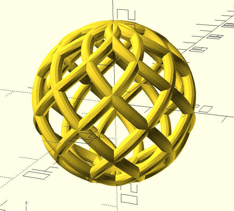
The code looks like this.
                              ////////////////////////////////////////
                              // VARIABLES

                              radius = 20; // sphere radius
                              pi = 3.14159; // pi ¯\_(ツ)_/¯
                              theta = 0;
                              alpha = 0;

                              // 3D line parameters
                              smooth = 10; // line smoothing - WARNING: increasing this value too much causes the compilation to take a long time.
                              line_w = 1.5; // line width

                              // Sphere position
                              x0 = 0;
                              y0 = 0;
                              z0 = 0;

                              h_n = 8; // horizontal lines

                              ////////////////////////////////////////
                              // FUNCTIONS
                              function MySphere(radius, theta, alpha) = let(
                                    x = x0 + radius * sin(theta) * cos(alpha),
                                    y = y0 + radius * sin(theta) * sin(alpha),
                                    z = z0 + radius * cos(theta)
                              ) [x, y, z];

                              function getPoints(d) = [
                                    for (i = [0:2:180])
                                       MySphere(radius, i, i*d)
                              ];


                              ////////////////////////////////////////
                              // MODULES

                              module line(start, end){
                                    hull() {
                                       translate(start) sphere(r=line_w, $fn=smooth);
                                       translate(end) sphere(r=line_w, $fn=smooth);
                                    }
                              }
                              module poly3Dline(points, index){
                                    if(index < len(points)){
                                       line(points[index - 1], points[index]);
                                       poly3Dline(points, index + 1);
                                    }
                              }

                              ////////////////////////////////////////
                              // TEST

                              //poly3Dline(getPoints(), 1);

                              ////////////////////////////////////////
                              // MAIN

                              for(i = [0:h_n]) {
                                    rotate(45*i)
                                    poly3Dline(getPoints(1), 1);
                              }

                              for(i = [0:h_n]) {
                                    rotate(45*i)
                                    poly3Dline(getPoints(-1), 1);
                              }
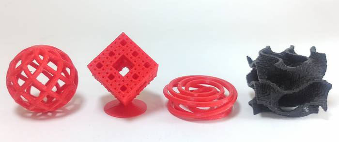
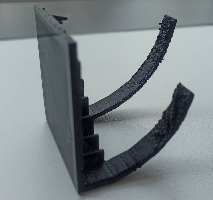
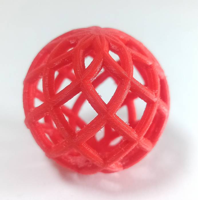
This figure was more attractive to print and that's what I did, but this time using Ultimaker PVA to print supports, the result is the following.
Level 3
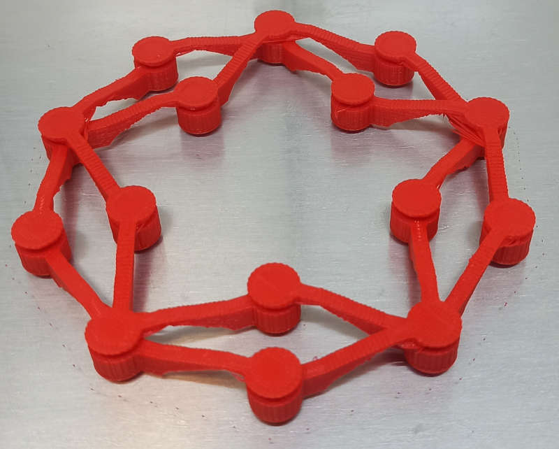
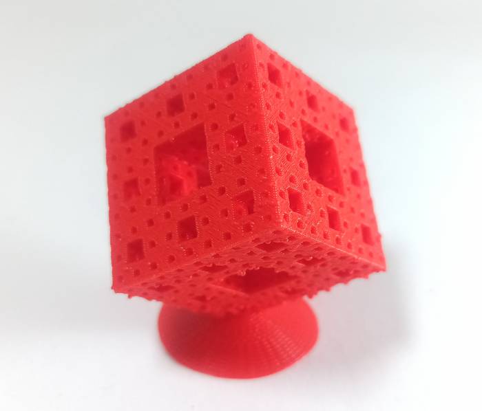
Here I wanted to be a bit more ambitious so I decided to make a Menger Cube, because it is a fractal and can be done by recursive methods the code becomes a bit more compact.
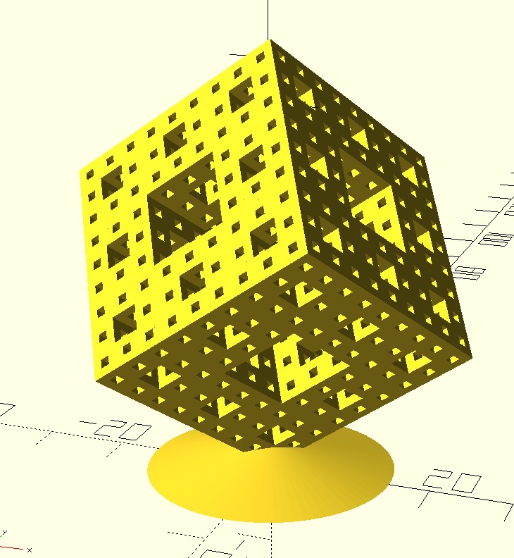
The code looks like this.
                              cube_size = 30;
                              iterations = 3;
                              pos = false;

                              smooth = 80;

                              rotate([45,-35,0])
                                  translate([(cube_size-1)/2,(cube_size-1)/2, (cube_size-1)/2])
                                  menger_cube(n = iterations, size = cube_size, p = pos);

                              cylinder(h=cube_size/7, r1=cube_size/2, r2=0, center=false, $fn = smooth);

                              module menger_cube(n, size, pos){
                                  if(n>0){
                                      for (i = [-1, 0, 1], j=[-1,0,1], k=[-1,0,1]){
                                          if (abs(i)+abs(j)+abs(k) > 1){
                                              translate([i*size/3, j*size/3, k*size/3])
                                                  menger_cube(n-1, size/3, pos);
                                          }
                                      }
                                  }
                                  if (n==0){
                                      cube(size, center = pos);
                                  }
                              }
I found the result very interesting to print and I did it (no support was necessary).
Level 4
Now I wanted something a little more abstract so I decided to design a Cinquefoil Knot, the result was very interesting.
The code looks like this.
                              k = 3;
                              pi = 3.14159;

                              // 3D line parameters
                              smooth = 10; // line smoothing - WARNING: increasing this value too much causes the compilation to take a long time.
                              line_w = 0.2; // line width

                              ////////////////////////////////////////
                              // FUNCTIONS
                              function CinquefoilKnot(k, u) = let(
                                    x = cos(u)*(2 - cos(2* u/(2*k + 1))),
                                    y = sin(u)*(2 - cos(2* u/(2*k + 1))),
                                    z = -sin(2* u/(2*k + 1))
                              ) [x, y, z];

                              function getPoints() = [
                                    for (u = [0:2:360*(k*4)])
                                       CinquefoilKnot(k, u)
                              ];

                              ///////////////////////////////////
                              // MODULES

                              module line(start, end){
                                    hull() {
                                       translate(start) sphere(r=line_w, $fn=smooth);
                                       translate(end) sphere(r=line_w, $fn=smooth);
                                    }
                              }
                              module poly3Dline(points, index){
                                    if(index < len(points)){
                                       line(points[index - 1], points[index]);
                                       poly3Dline(points, index + 1);
                                    }
                              }

                              ////////////////////////////////////////
                              // TEST

                              scale(5)
                              poly3Dline(getPoints(), 1);
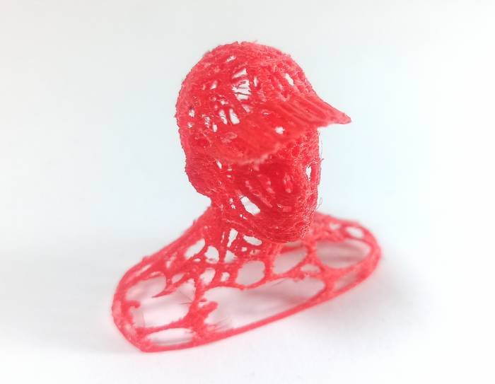
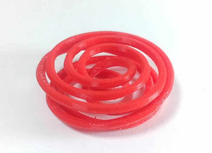
After printing it looks like this, this print if it was necessary to use support that's why I used PVA Ultimaker.
Level 5
In this last level I decided to experiment a little more with surfaces but OpenSCAD is not very good at modeling surfaces,
so the solution I found was to get slices of the surface I wanted to model and place a cube in that chorded point to get a
surface built from cubes, this surface is a Gyroid.
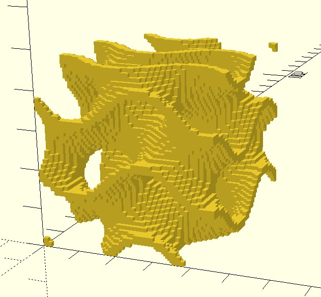
The code looks like this.
                              angle = 450;
                              shape_size = 10;
                              order = 0;


                              module MyGyroid(angle, shape_size, order){
                                  for(x=[0:order],
                                      y=[0:order],
                                      z=[0:order])
                                      translate([(angle/shape_size * x),
                                          (angle/shape_size * y),
                                          (angle/shape_size * z)]) {

                                      for(i=[0:shape_size:angle], j=[0:shape_size:angle], k=[0:shape_size:angle]){

                                          num = ((cos(i) * sin(j)) + (cos(j) * sin(k)) + (cos(k) * sin(i)));

                                          if ((num < 0.2) && (num > -0.2)) {
                                                  translate([(i/shape_size),(j/shape_size),(k/shape_size)])
                                                      cube([1.2,1.2,1.2]);
                                          }
                                      }
                                  }
                              }

                              /////////////////////////////
                              // MAIN

                              MyGyroid(angle, shape_size, order);
The print result is as follows.
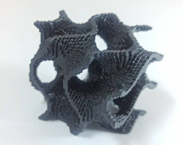
As you can see in this 3D printed part it cannot be made by subtractive manufacturing methods because it has many intrinsic parts, also the tool cannot access all areas of the part which makes it difficult to manufacture it subtractively.
Like any technology 3D printing has advantages and disadvantages. To mention some advantages we have rapid prototyping, it prints what is needed without removing material as in subtractive methods, flexibility in design as it allows printing objects that are complicated or impossible to achieve by other methods. Some limitations are; printing time, printing area available, no final finish is achieved so it is necessary to perform post-processing for a final surface and difficulty to scale it to mass production.