Making of a vinyl cutter, Jeff's contribution
Everything started with a couple of meetings with our instructors to decide the machine were going to make and schedule its development.
3D design
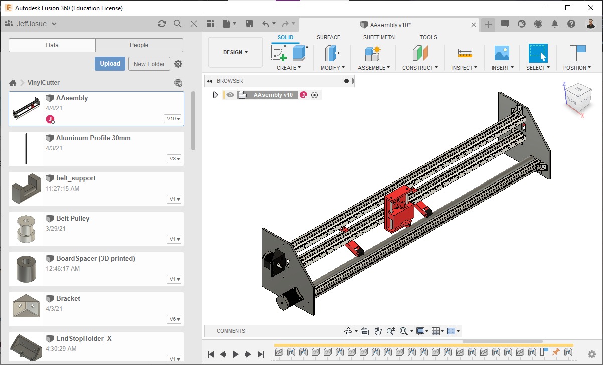
I did a project in Fusion 360 to which I added my colleague and instructors:
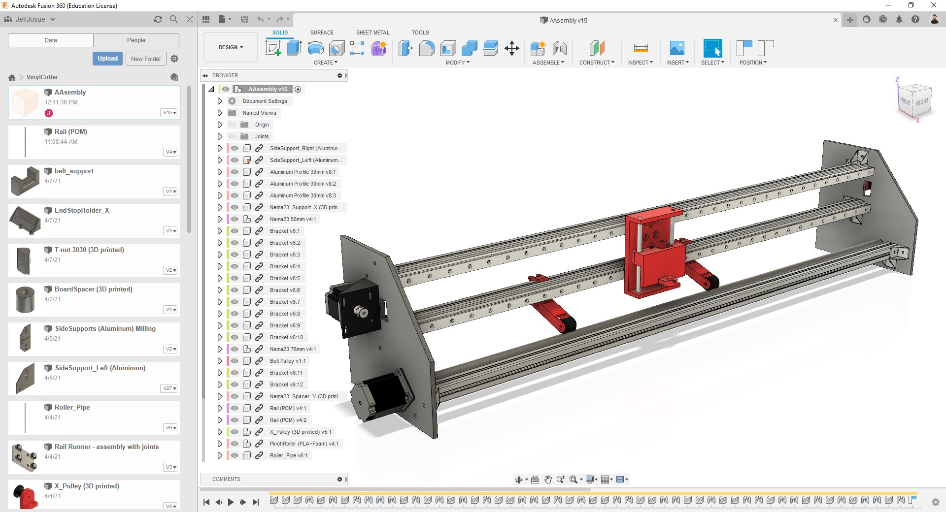
I did most of this part:
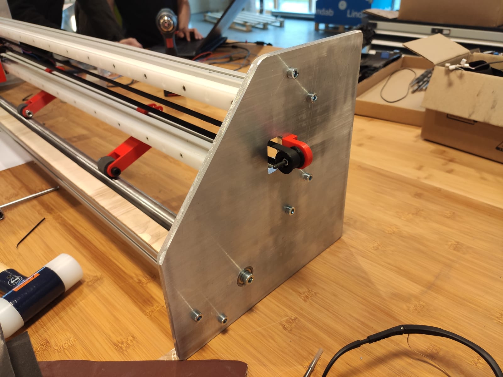
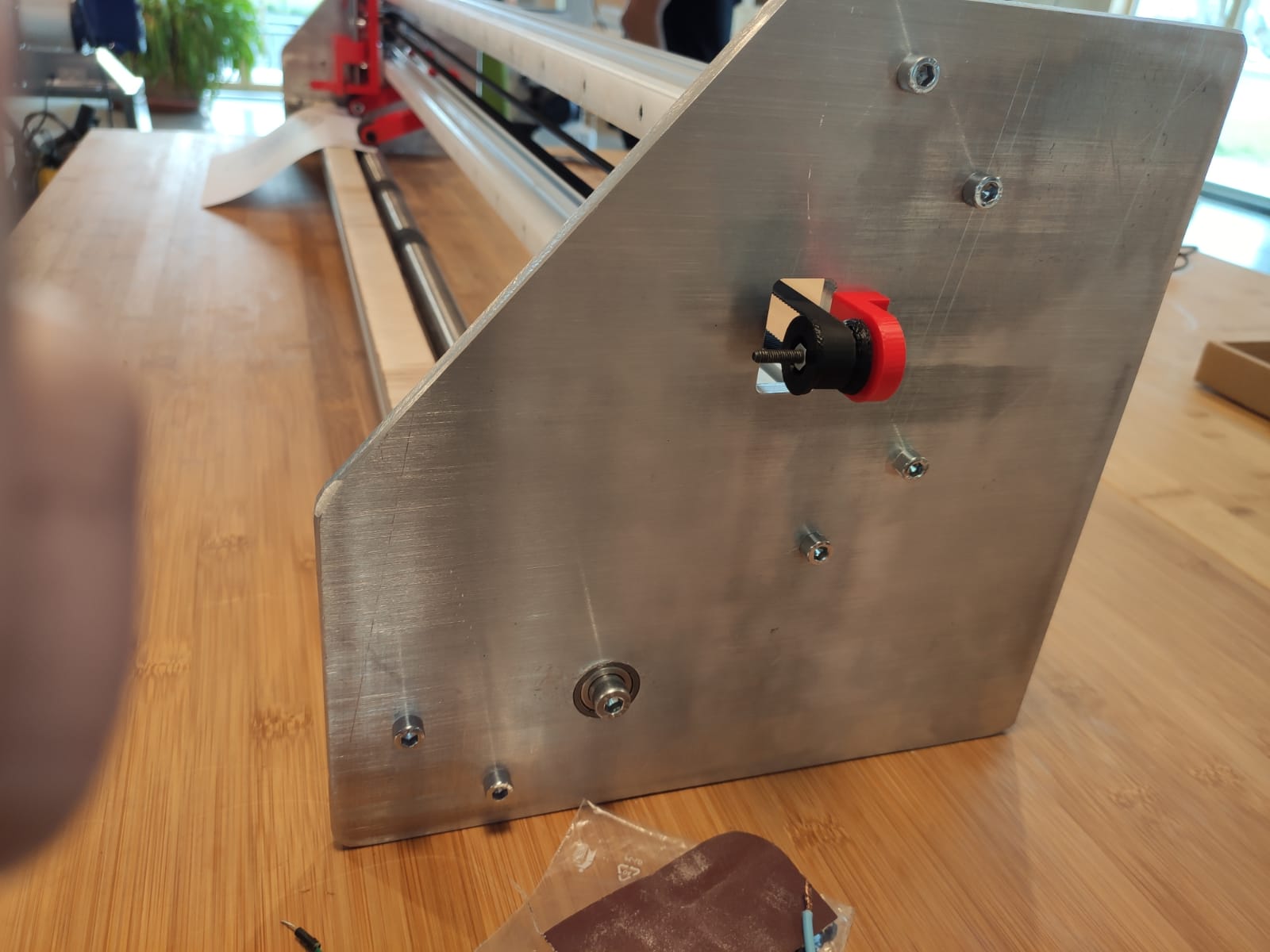
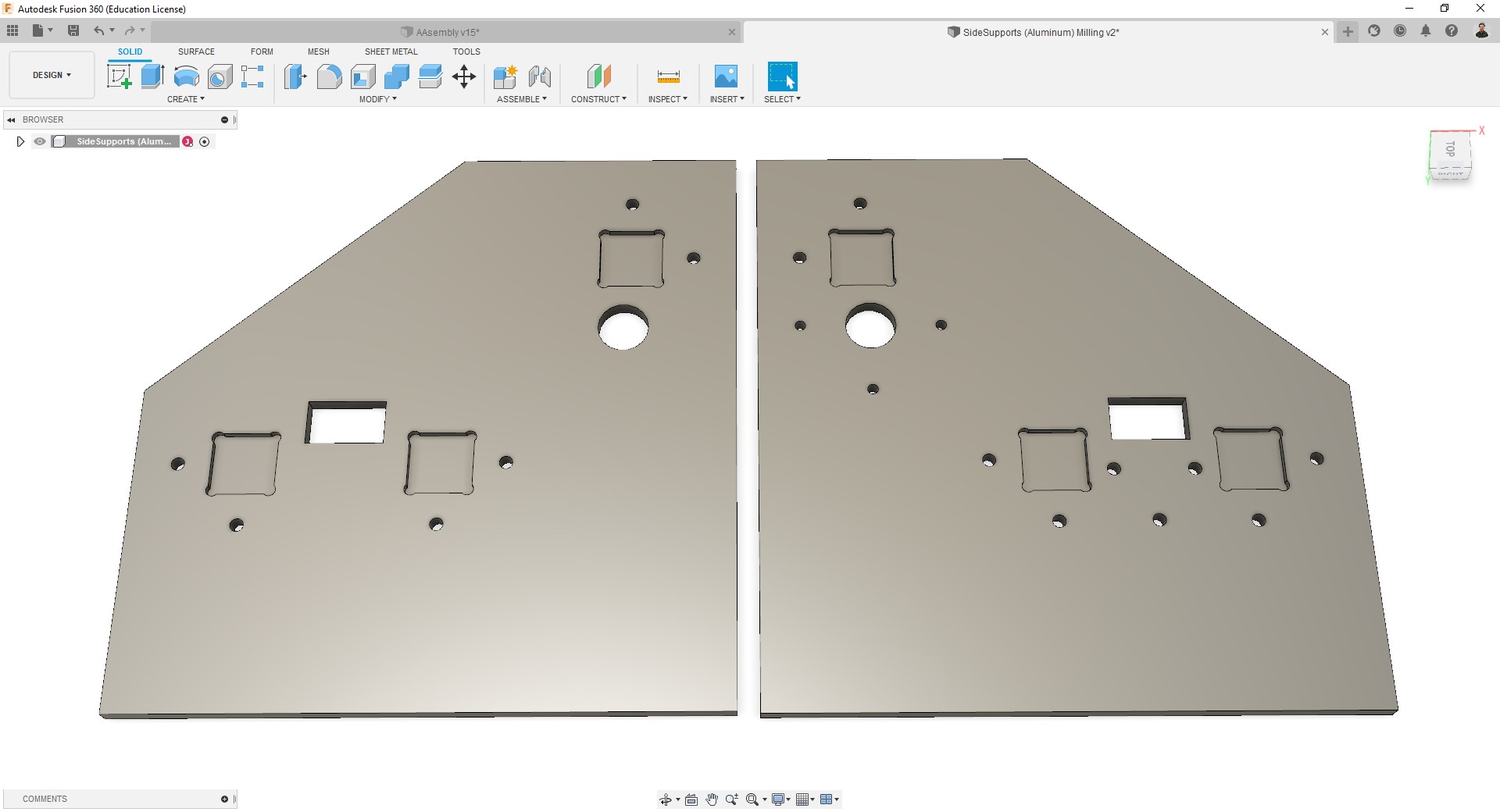
- The side supports, which I worked the hardest on.
- Motor holders.
- Coupling to connect the roller with the Y axis motor.
- I modeled the motors, aluminum profiles, linear rails, rail runners, roller, and brackets.
- Since we were missing two T-nuts I have also modeled it for 3D printing.
- I have also made the 3D assembly.
-
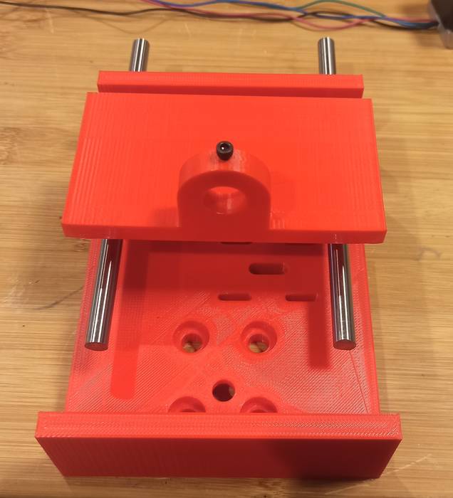
Side supports:
-
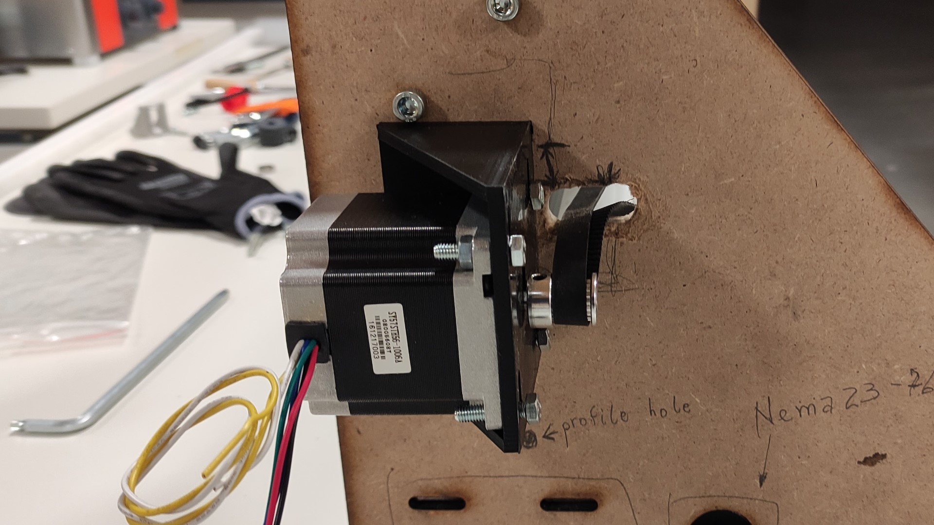
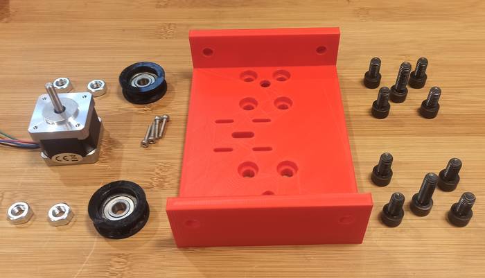
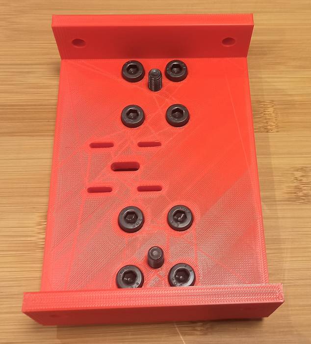
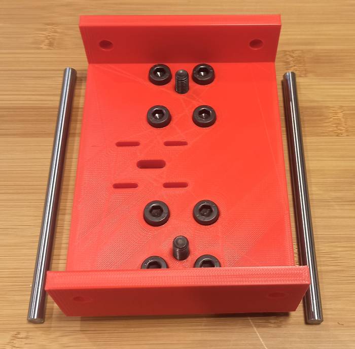
Nema23 holder:
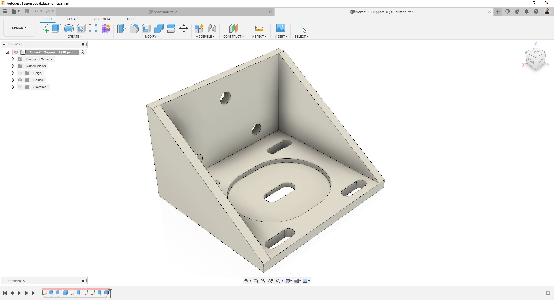
This design offer a no-fixed position for the motor, so you can move it by a distance of 1 cm. -
T-nut:
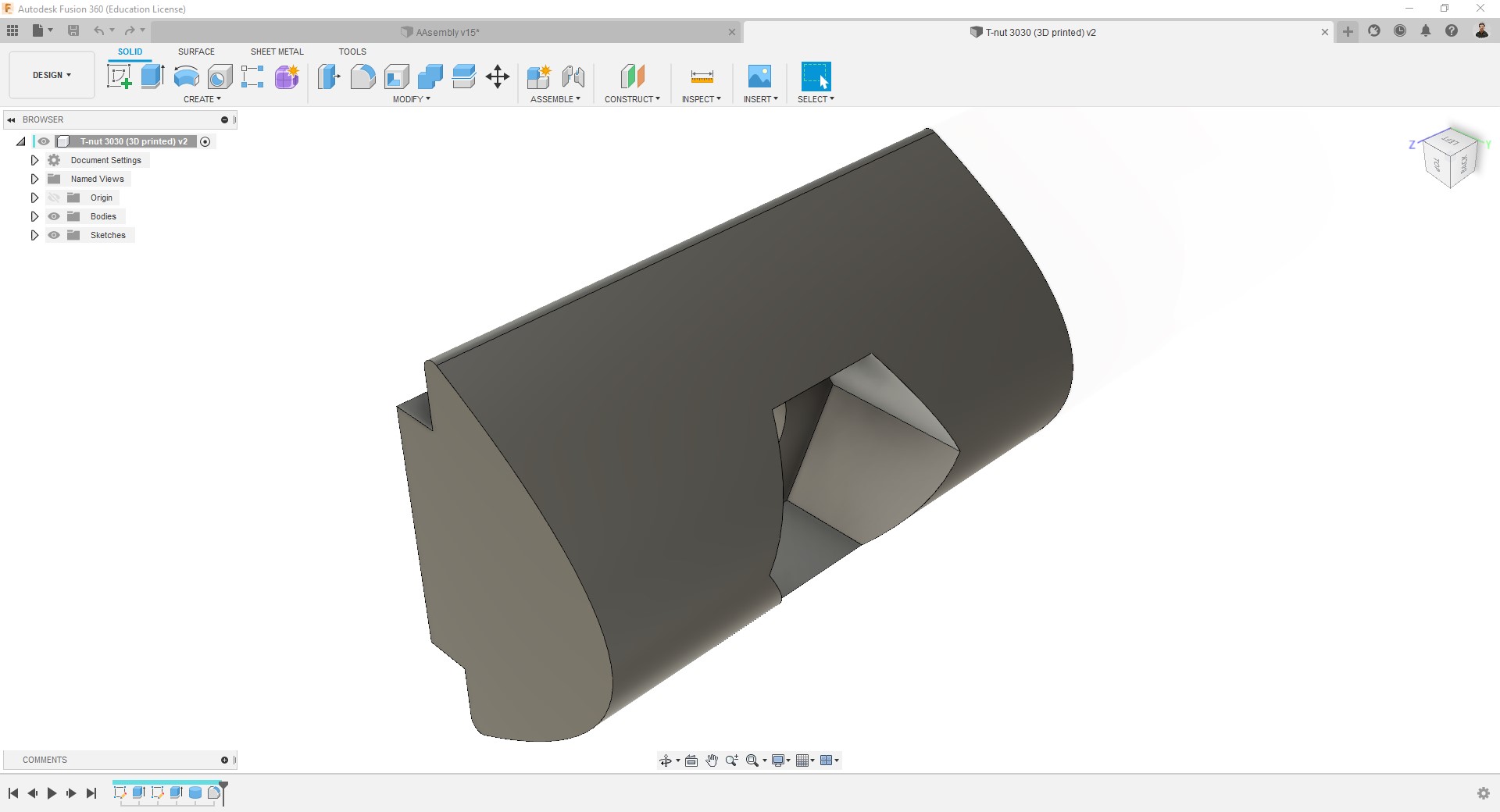
This model includes includes a pocket to introduce a M3 nut. -
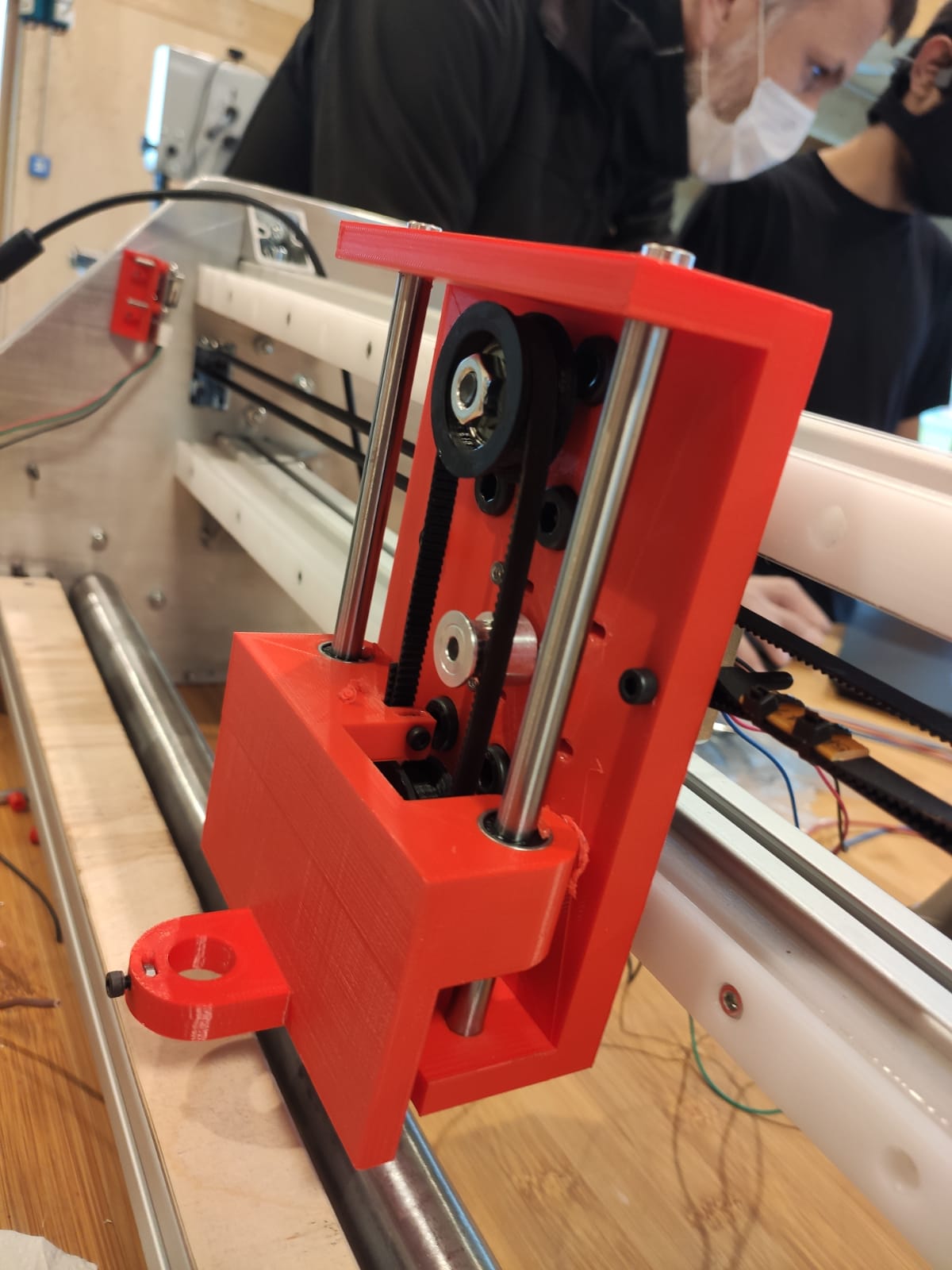
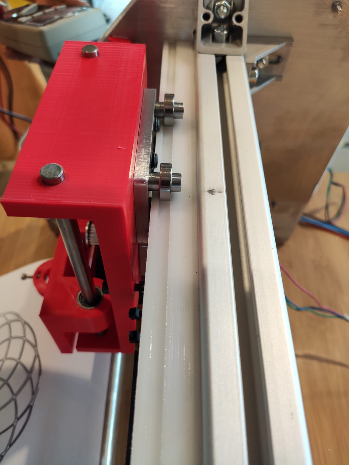
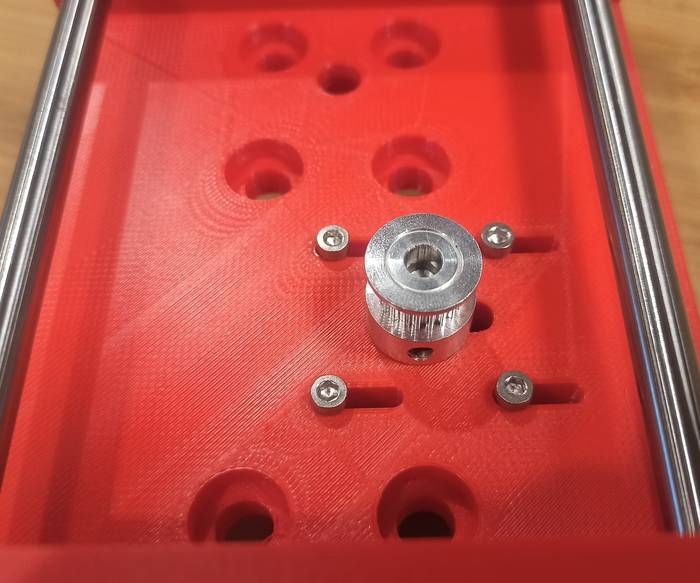
Coupling:
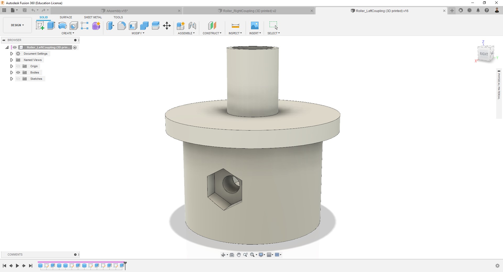
This model includes includes two pockets (one inside and another outside) to introduce M3 nuts, to adjust the motor shaft.
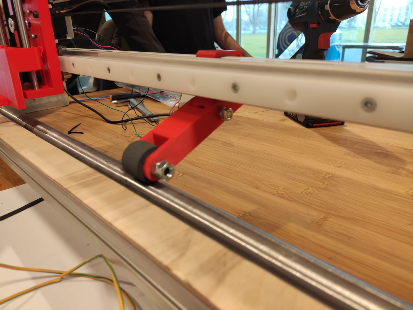
Roller and Cutting bed
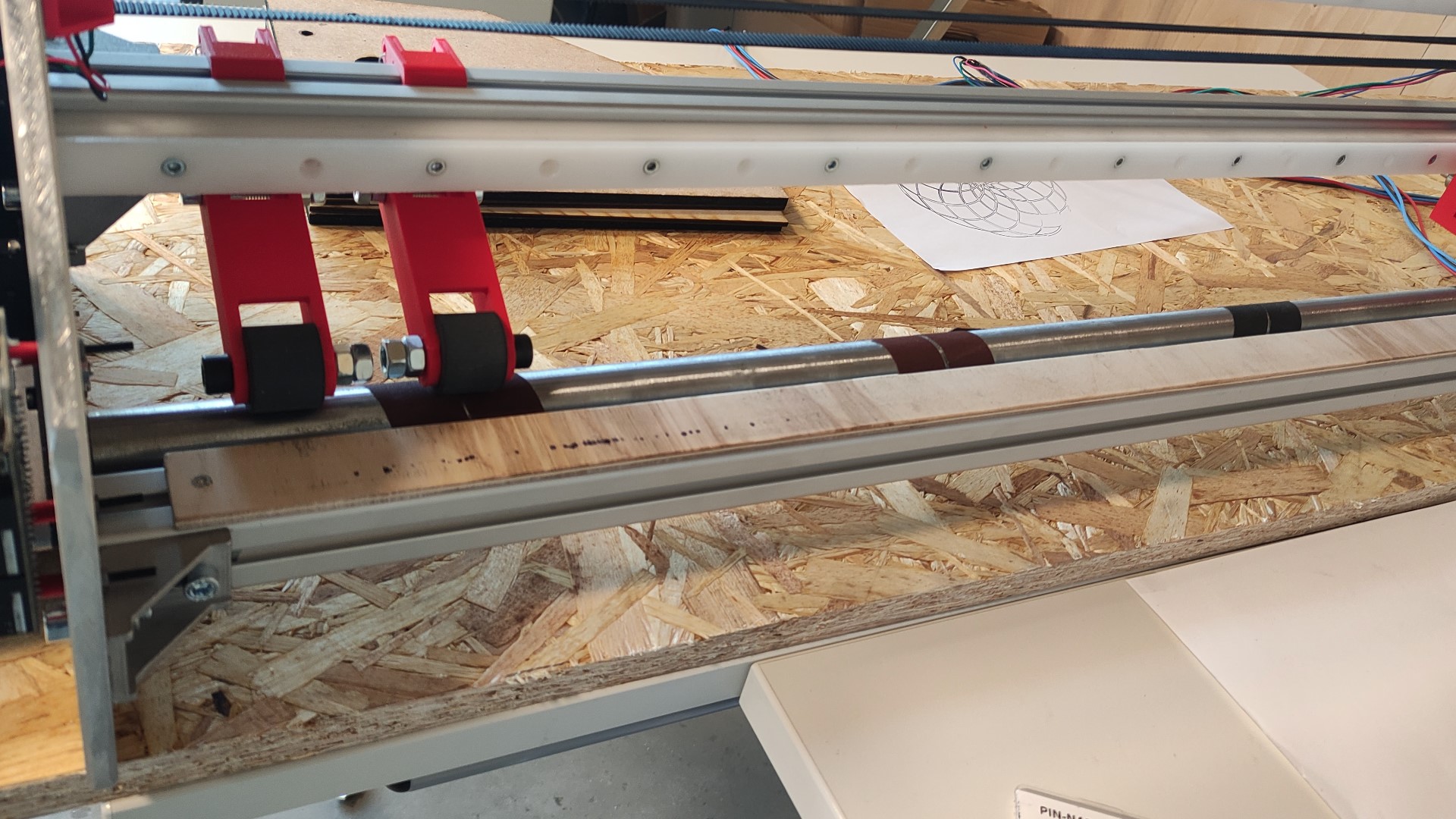
- I have cut and sanded a metallic pipe to use it as a roller for the Y axis.
- I have glued some sandpaper to the roller for creating friction against the vinyl/paper.
- A cutting bed of a material such as nylon was needed but since we were almost out of time, I improvised a wooden bed which I attached using my 3D printed T-nuts.
- I have also cut the aluminum profiles.
3D printing
-
Nema23 holder:
Print summary:
- 3D printer = Ultimaker S5.
- Filament = 2.85 generic black PLA.
- Nozzle = AA0.4
- Layer height = 0.2mm
- Wall = 1.2mm
- Infill = 50%, Lines.
- Support = Disabled.
- Build plate adhesion = None. -
T-nuts:
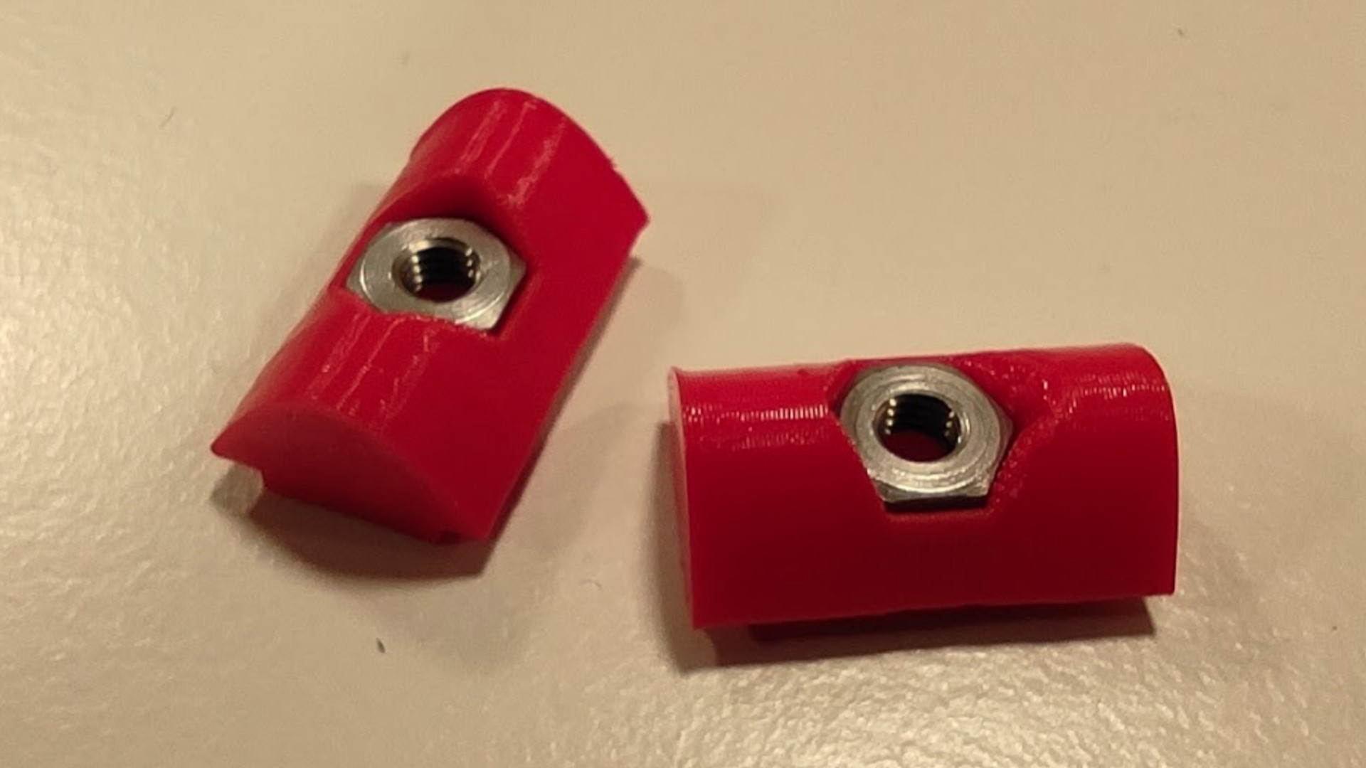
They resulted being stronger than I expected.
Print summary:
- 3D printer = Ultimaker S5.
- Filament = 2.85 generic red PLA.
- Nozzle = AA0.4
- Layer height = 0.2mm
- Wall = 0.8mm
- Infill = 100%, Grid.
- Support = Disabled.
- Build plate adhesion = Brim. -
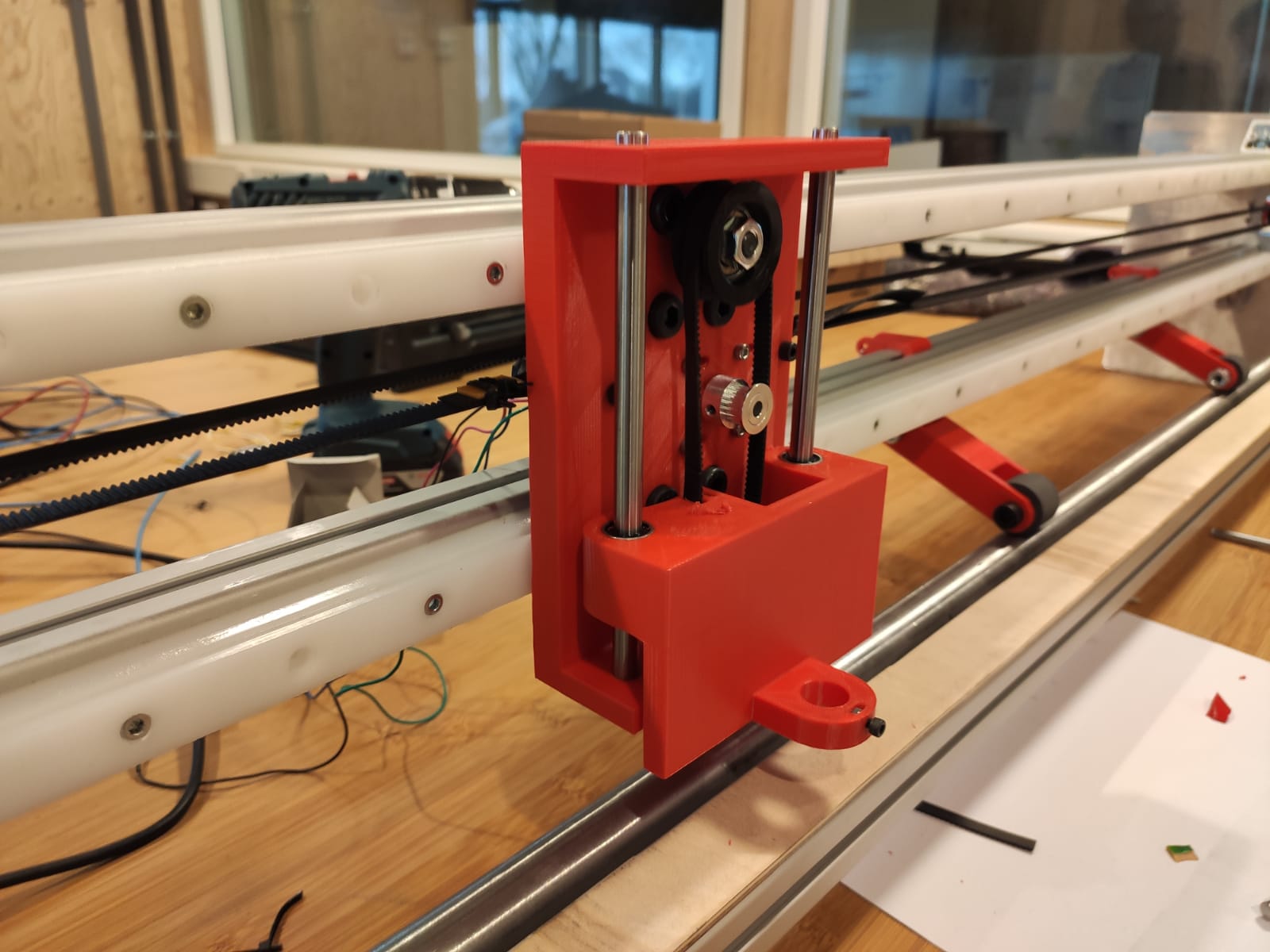
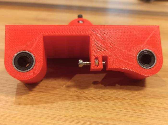
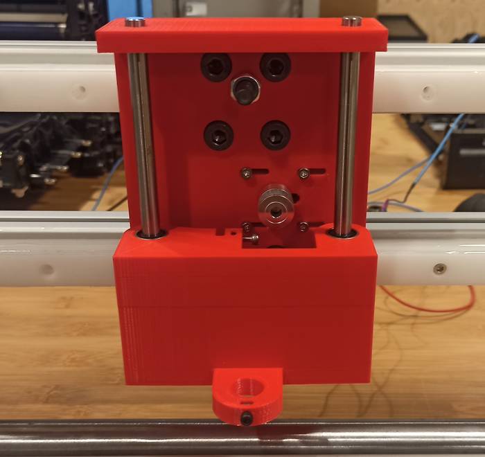
Coupling:
- This is the printed part with the nuts.
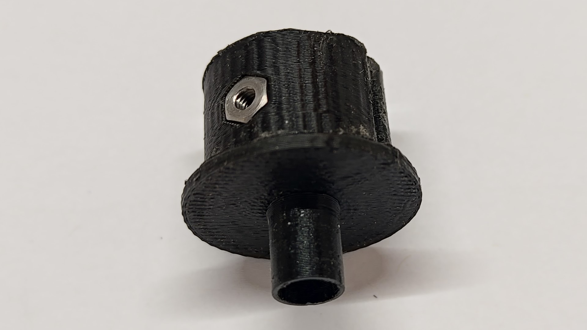
- This is how it looks mounted on the machine. It’s probably not the best material for this application, but it worked! 😄
Print summary:
- 3D printer = Ultimaker S5.
- Filament = 2.85 generic black PLA.
- Nozzle = AA0.4
- Layer height = 0.2mm
- Wall = 1.2mm
- Infill = 50%, Grid.
- Support = Disabled.
- Build plate adhesion = None.
- This is the printed part with the nuts.
Computer controlled cutting
-
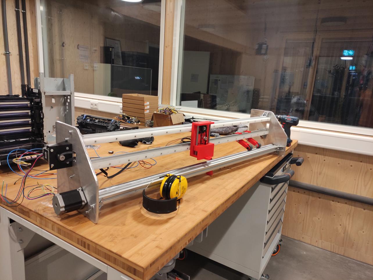
Before making the side supports with the official material (aluminum), I have made test pieces in MDF which I laser cut.
-
First goal was testing stability of the design:
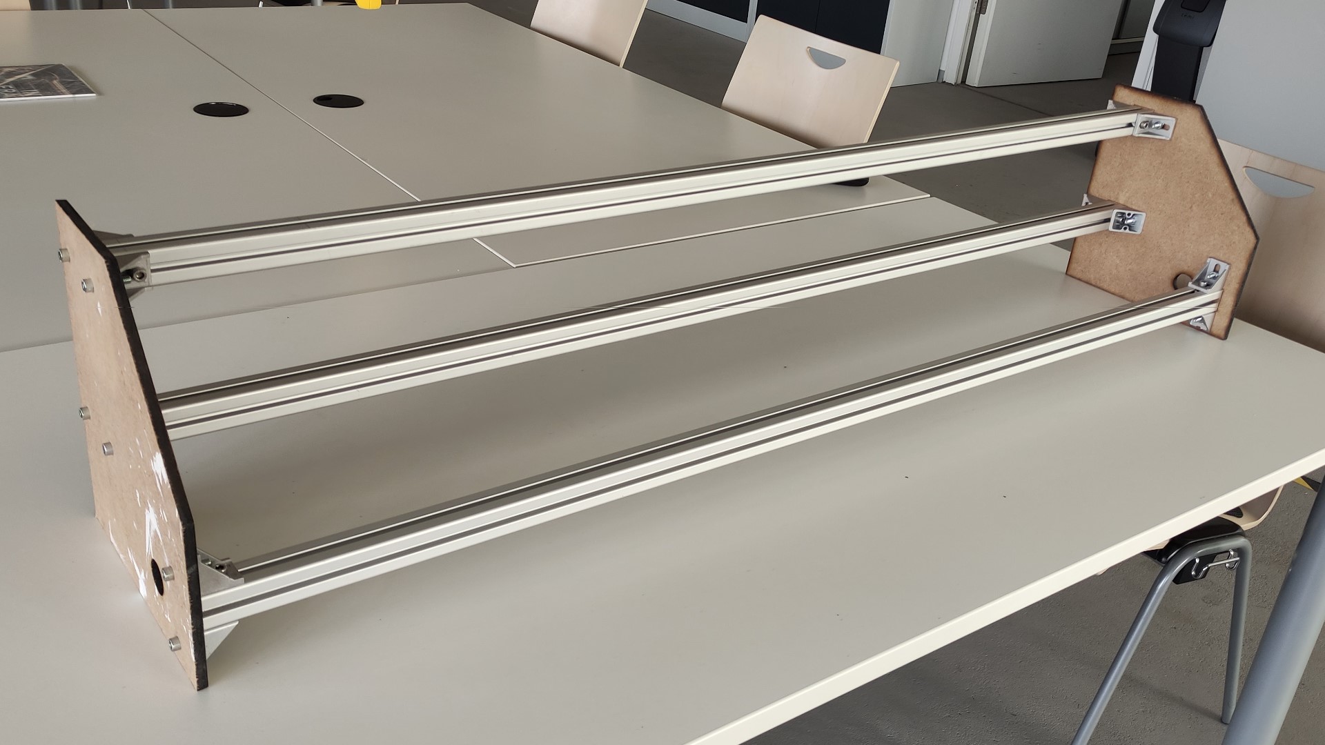
It was very stable, more than all of us expected. -
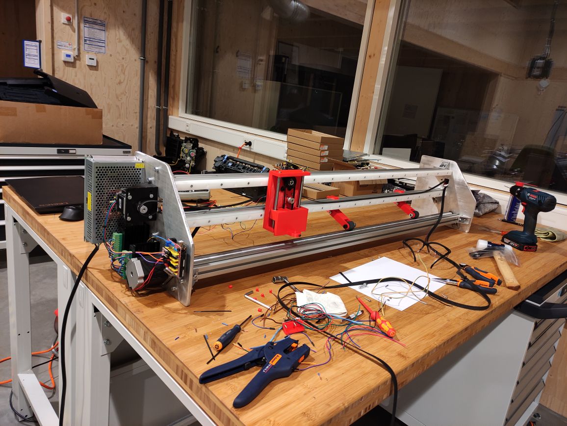
Secondly, these pieces serve to consider the necessary modifications:
After this I have added an extra space in the back for the electronics, made holes for the X axis belt, and moved some screw holes for the brackets.
Computer controlled machining
- I prepared the g-code with my instructor using the Manufacture workspace of Fusion 360:
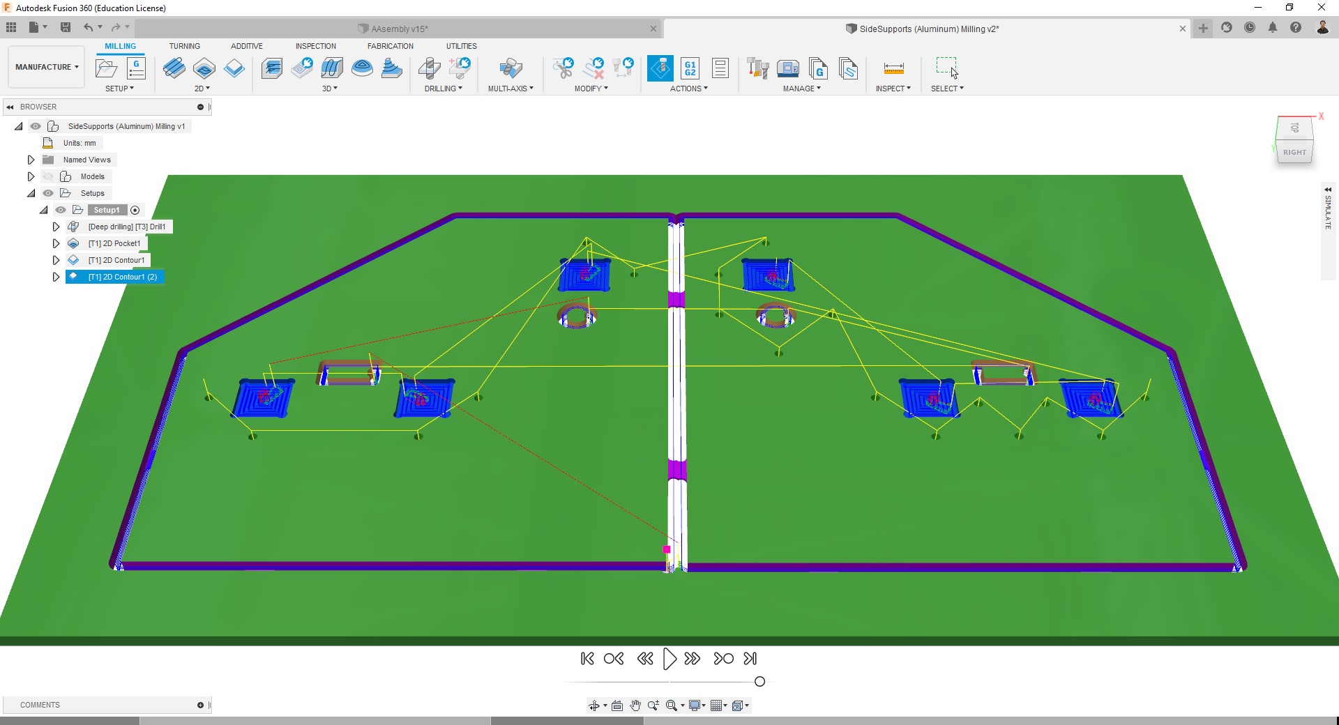
The toolpaths used for it were:
- Drilling - with a Ø5mm drilling tool.
- Pocket - with a Ø6mm milling tool.
- Contour - with a Ø6mm milling tool.
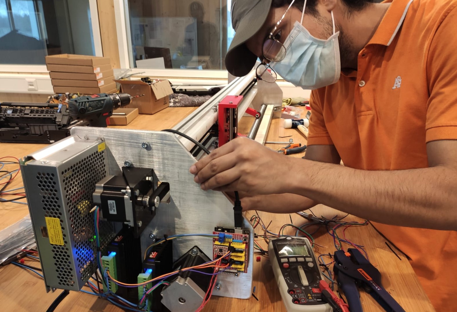
Since due to Corona-restrictions the access to the FabLab was almost impossible during these days, I have gone to Daniele Ingrassia‘s Lab for milling.
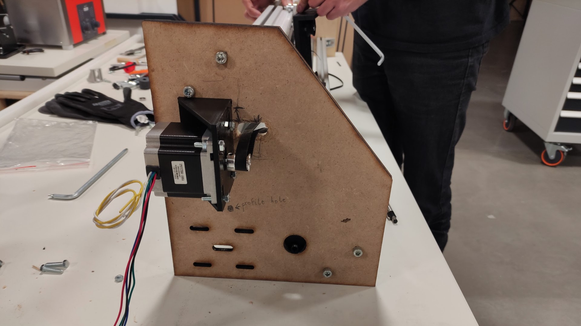
- I milled it with my instructor and then I have sanded the pieces.
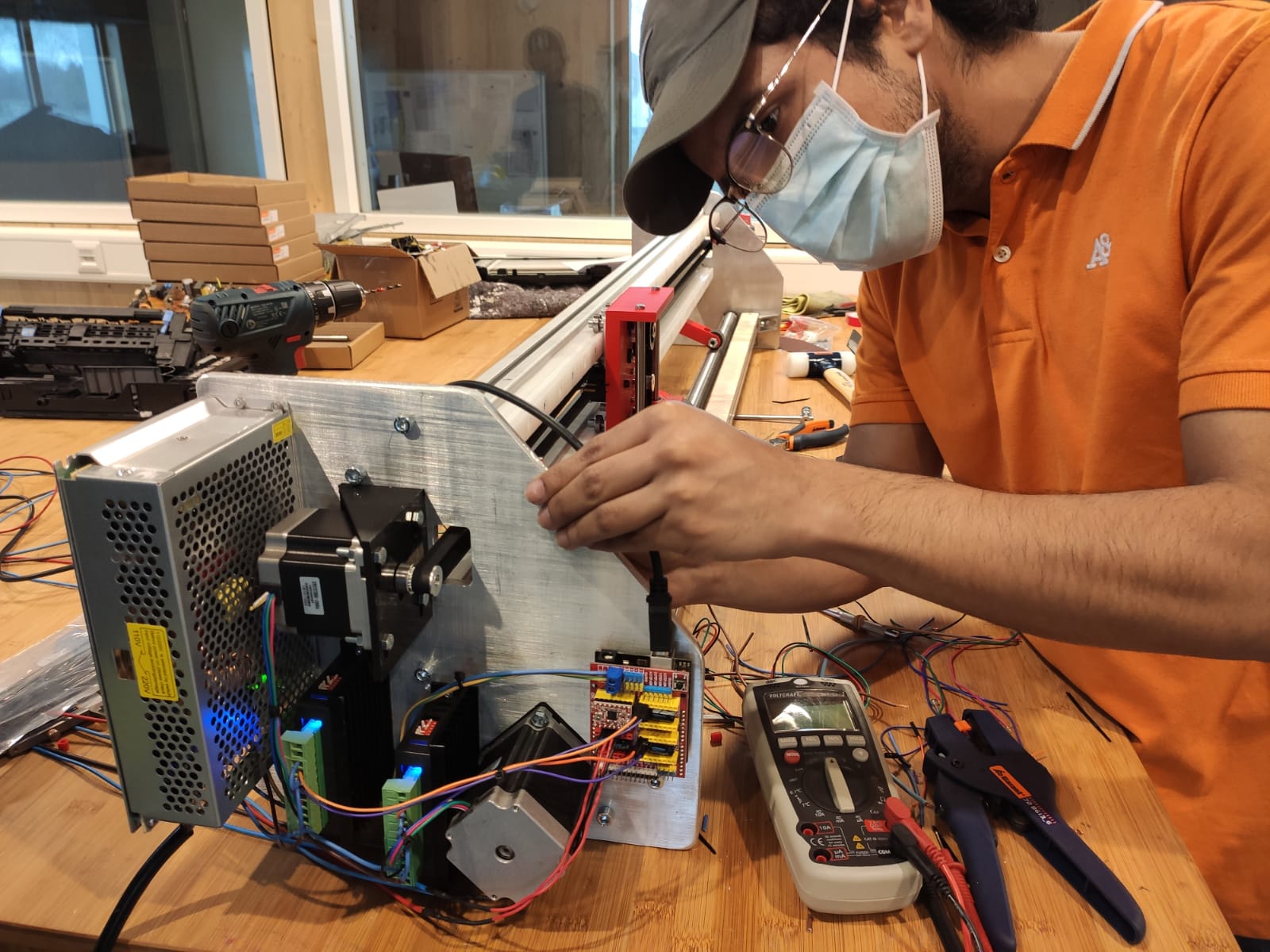
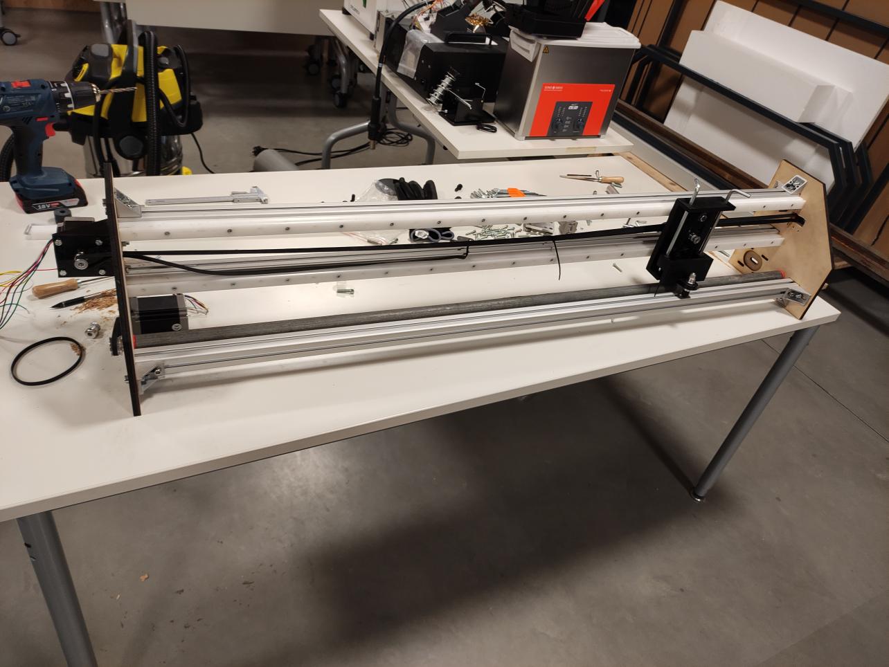
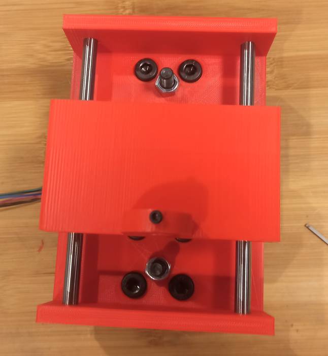
- On one of them we have mounted the motors and electronics:
- While the other is rather freer:
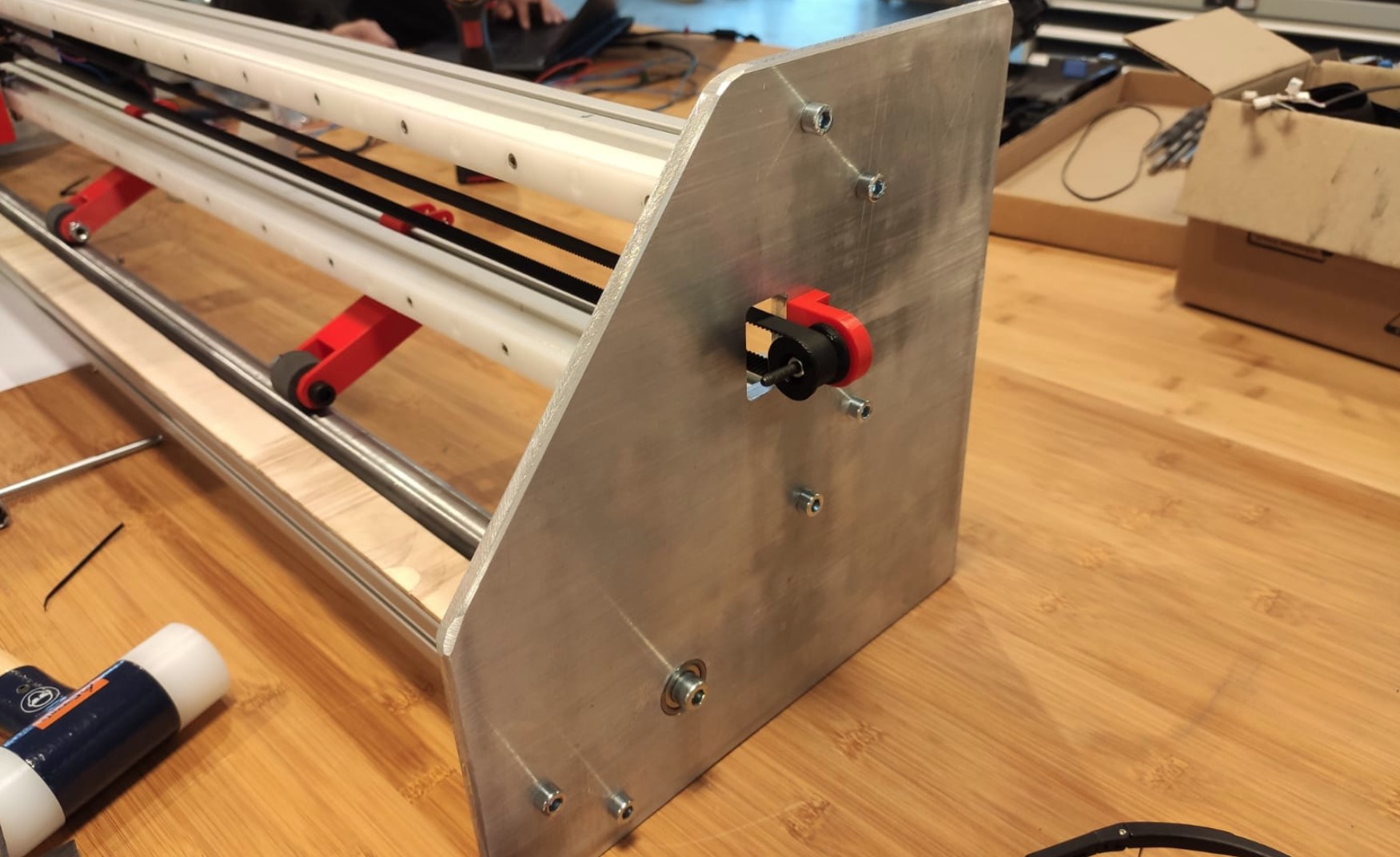
- On one of them we have mounted the motors and electronics:
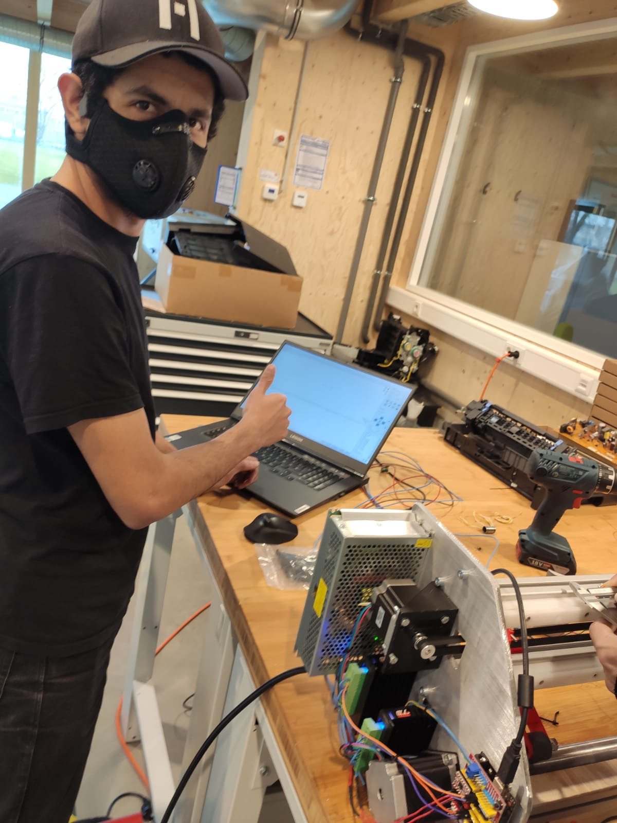
Machine performance
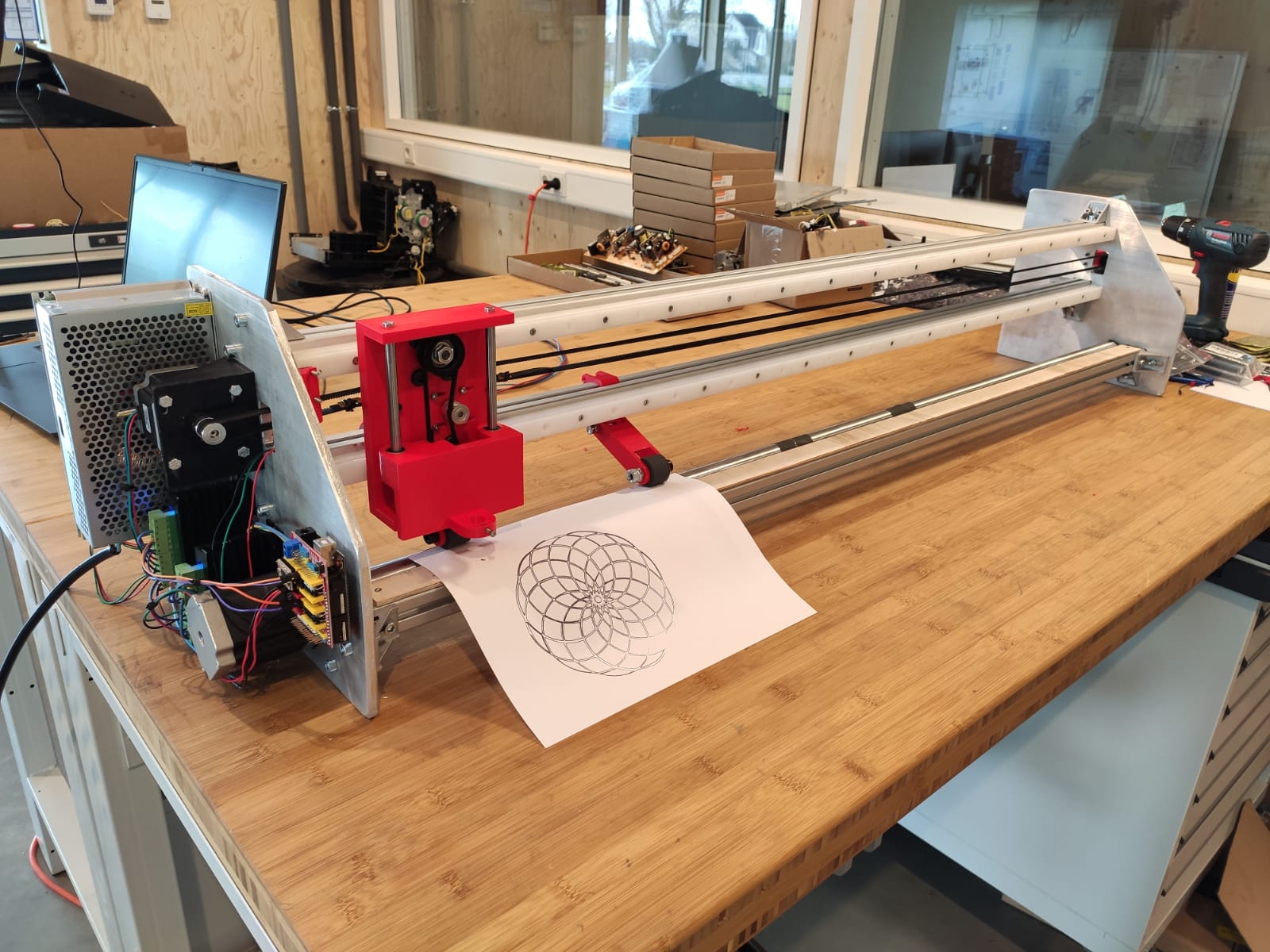
Finally, we used a marker to make a test of its behavior:
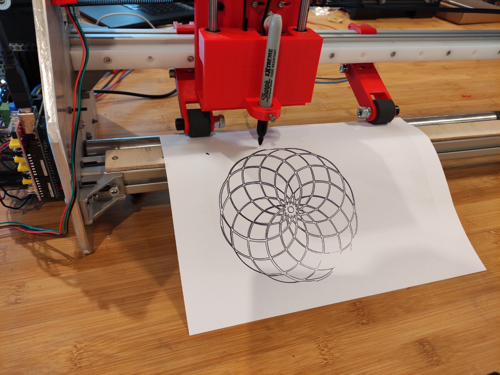
Test result:
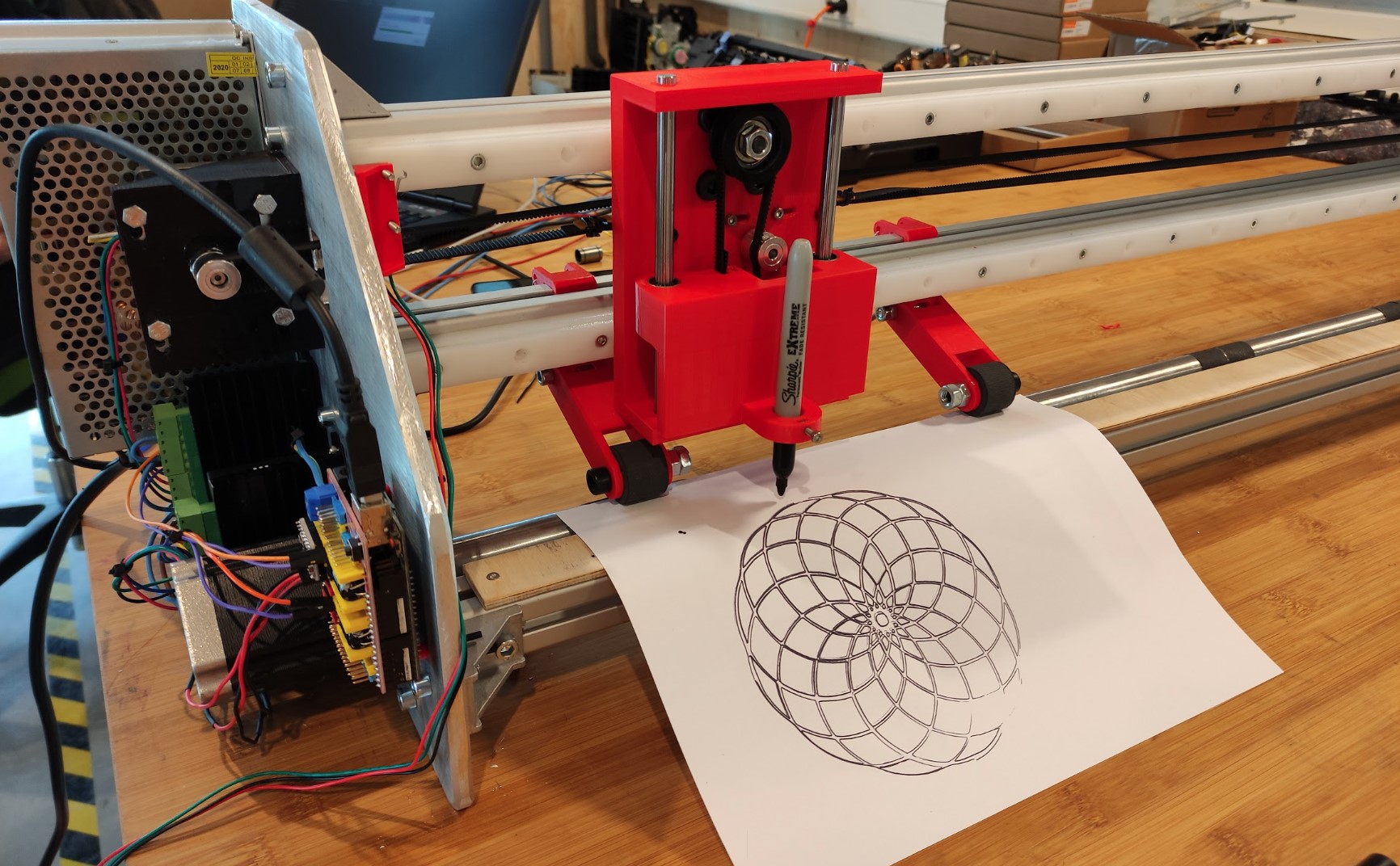
The small parts not drawn are because the bed is not completely flat, I have not managed to cut it evenly with the band saw. That’s also why we haven’t used the knifes and test it with vinyl.
Outlook:
- Even when the goal is making a Vinyl cutter, at this point (testing it with a marker) it works perfectly fine as a plotter machine.
- We already have the knives for cutting (also the Z axis mechanism was already designed to use the knives), but current the not-uniform bed could lead them to damage and also wood is not the best material for it.
- Later we’ll change the bed and use the knives to make the machine cut vinyl.
Files
- Nema23Holder.stl
- T-nut.stl for 30x30 aluminum profiles.
- Fusion project File: download.
Making of a vinyl cutter, Harley's contribution
This week's assignment is to design and build a machine as a group with all Fab Academy participants in the Kamp-Lintfort node, the machine should include mechanism, actuation and automation.
This page documents my individual contribution during the process. Together we decided to realize an approximately 1.2 meter vinyl cutter.
I started the design process by looking at the mechanisms used by commercial vinyl cutters, how they work and the types of actuators they use. I designed the Pinch Roller and the head for the Z-axis.
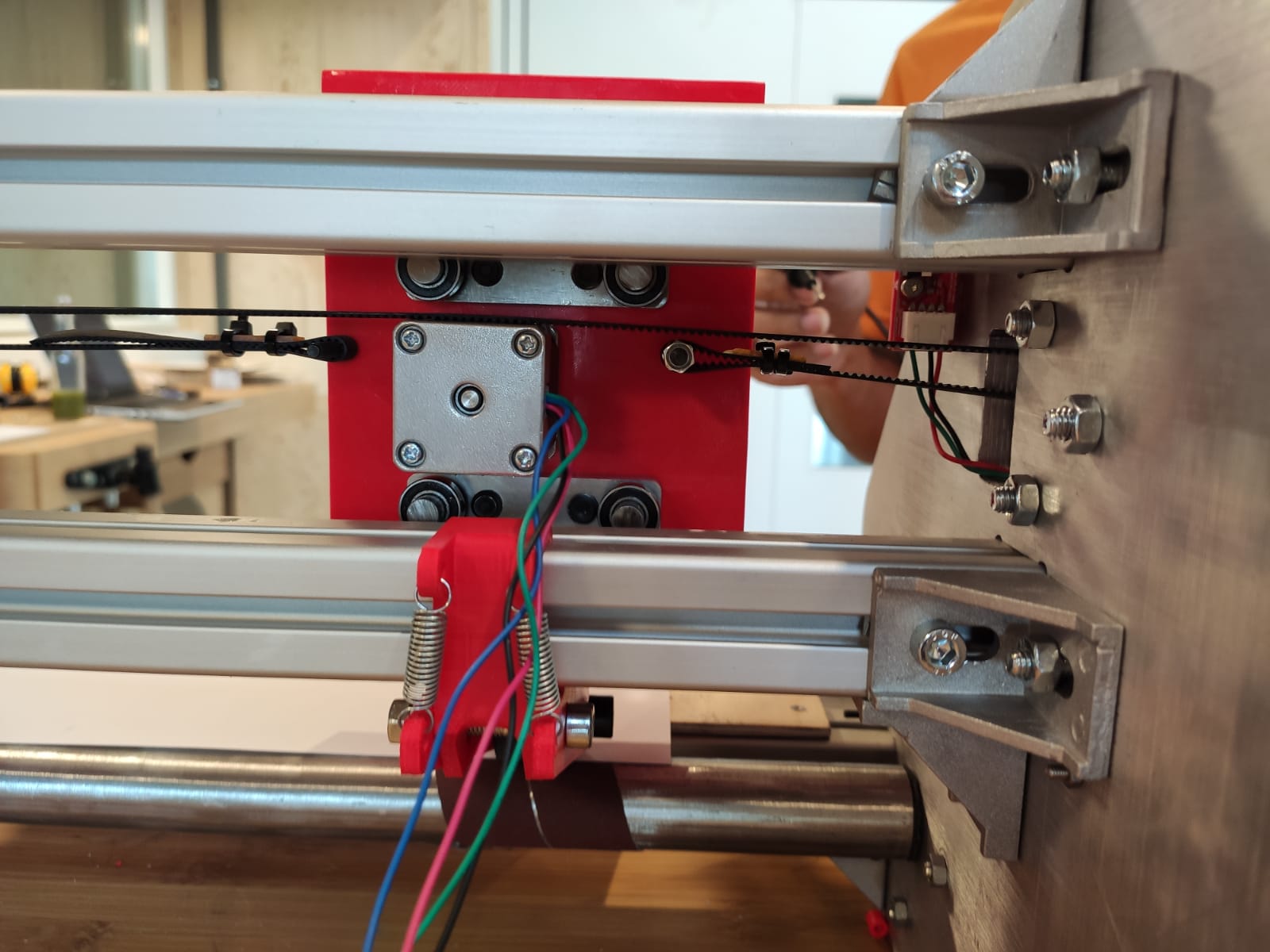
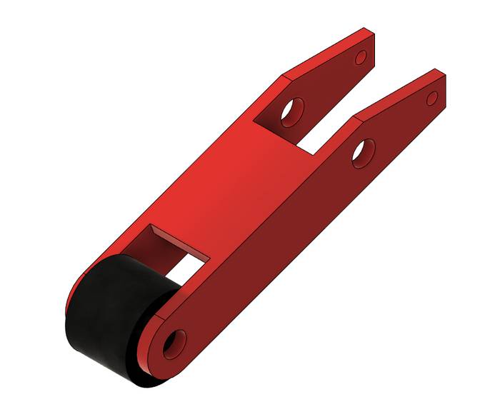
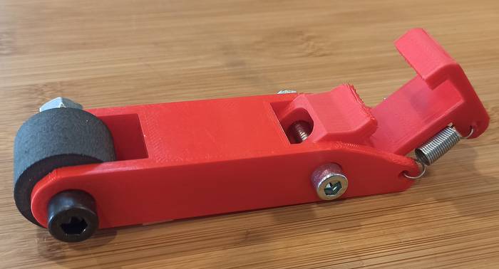
First I designed the Pinch Roller which is a part that is responsible for keeping the vinyl sheet pressed against the Drive Roller so that it can move the sheet back and forth.
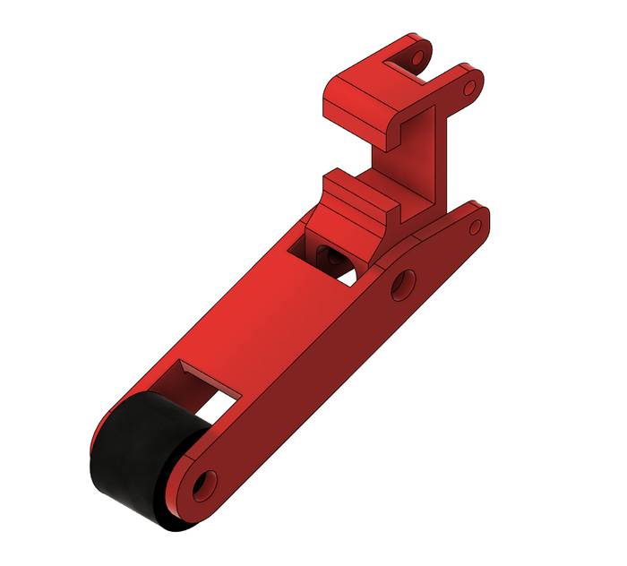
At the end of a Pinch Roller there should be a rubber roller, that element was extracted from a discarded printer and reused in our design.
The Pinch Roller must also have the ability to attach to the aluminum profile of the frame and raise and lower its end to maintain pressure, this was accomplished with some springs on the back, using compression springs to maintain force against the Drive Roller.
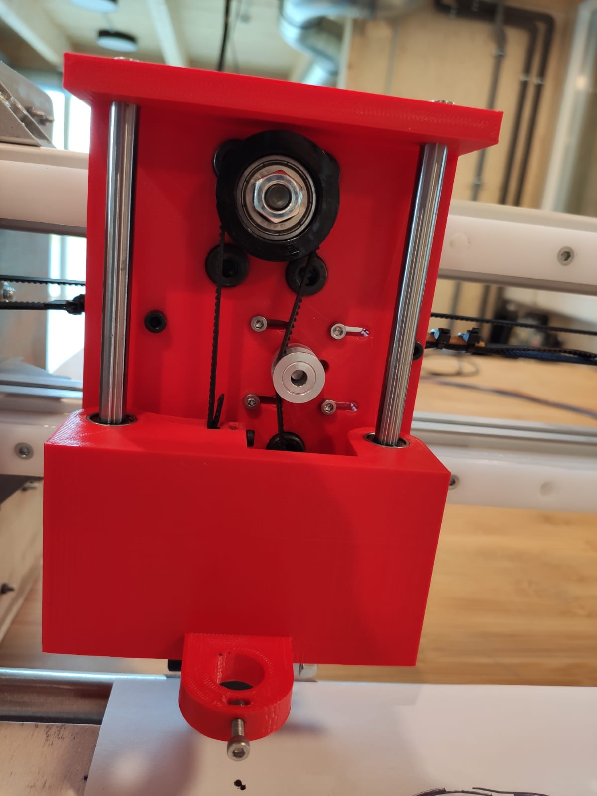
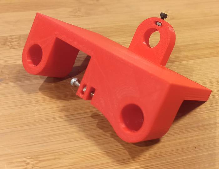
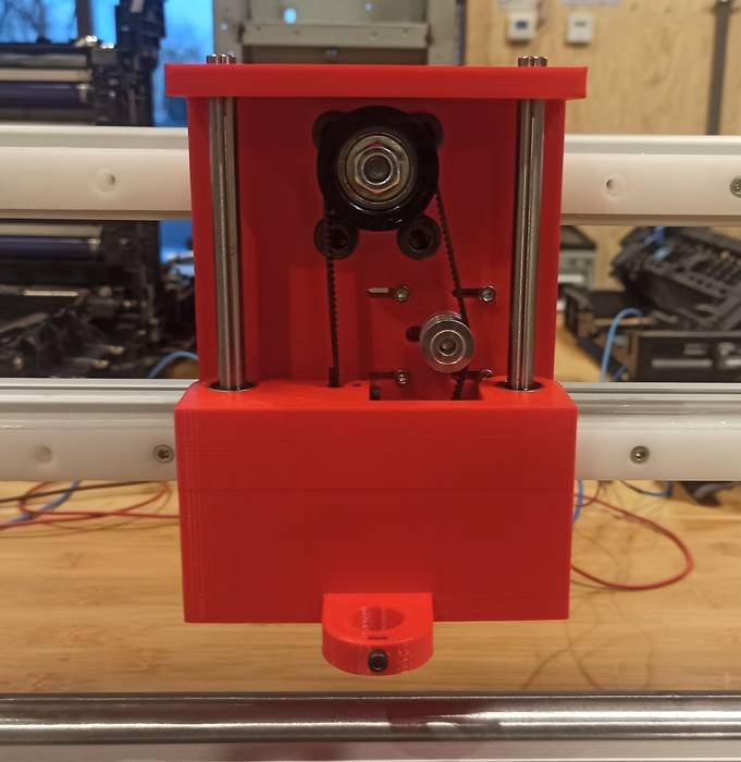
The next element designed was the Z-axis head, after discussing the actuator to use we decided to use a stepper motor, specifically a NEMA 11.
This element must be able to be fastened to the rails and also the motor and the cutting blade must be placed on it.
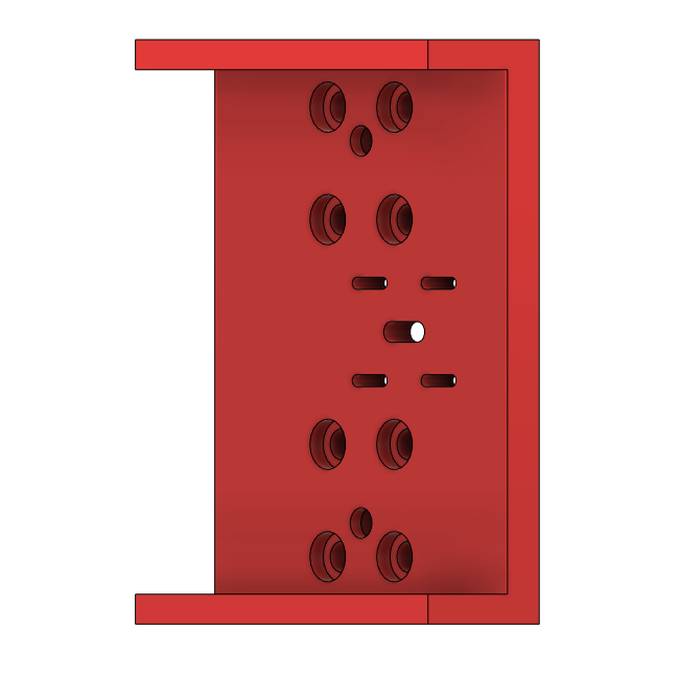
A pair of shafts and bearings are being used to move it up and down.
The last part of this piece is the one that must go up and down and hold the cutting blade.
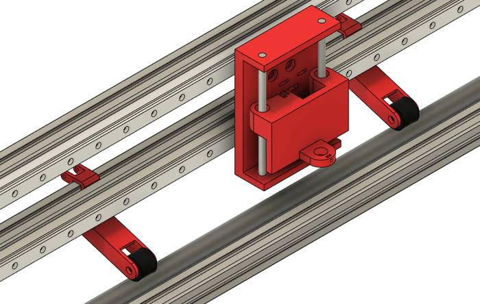
The result of the Pinch Roller and Z-axis head on the frame looks like this.
A rendering of the complete machine is as follows
After 3D printing the parts the next process is to assemble and test them.
Start by assembling the Pinch roller, the components that are part of it are shown below.
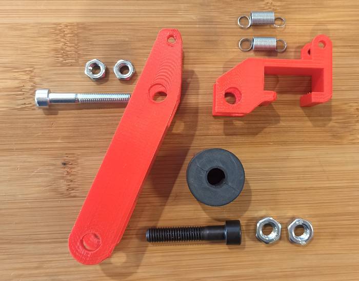
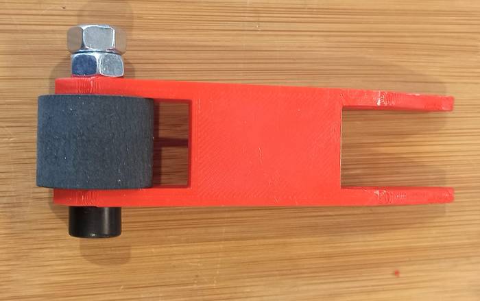
To hold the rubber roller, two nuts are used to keep the pinch roller on place.
Using an M4 nut as an axis in the rotating union of the Pinch Roller.
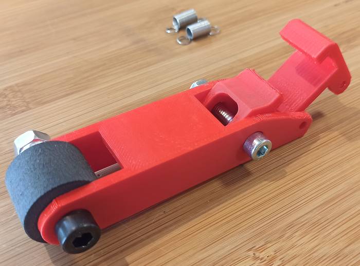
Finally it is a matter of mounting the springs on the back.
With the Pinch Roller completely assembled, the only thing left to do is to place it on the structure.
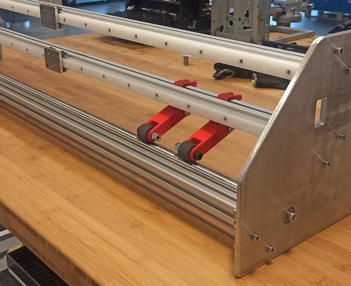
They work very well, they have enough pressure to keep the vinyl sheet with the Drive Roller.
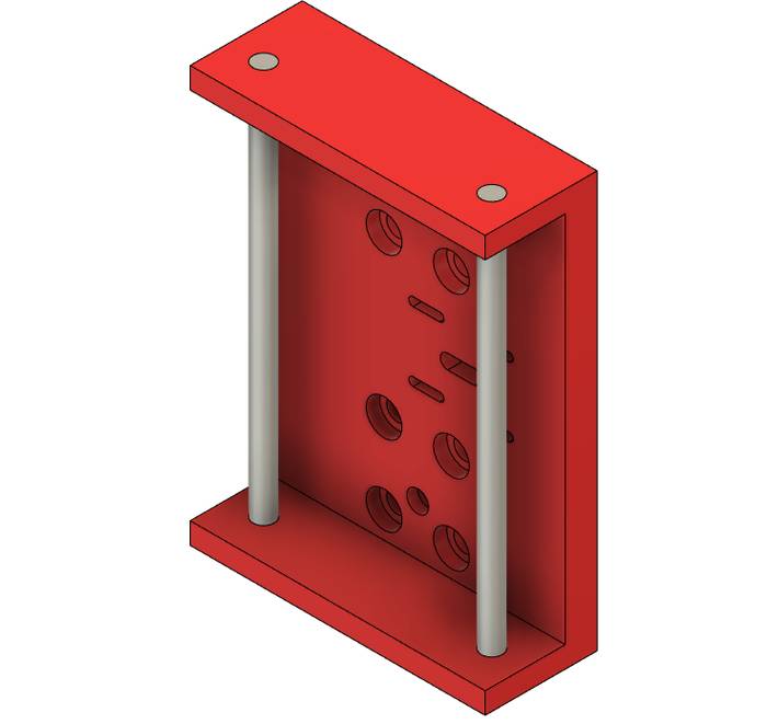
The next item to assemble is the Z-axis, start by placing the bearings in the holes where the shafts will pass through.
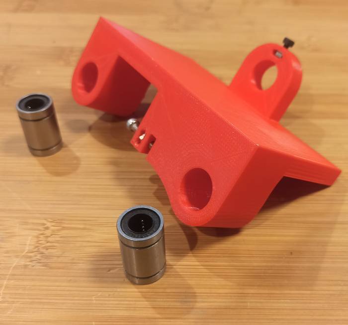
The type of joint is fixed pressure so that the bearings stay in place without moving.
The elements used for the rail clamping part are shown in this image.
Start by attaching the locking nuts.
After that the axis were placed.
Before placing the shafts completely it is necessary to leave a space to place the mobile part.
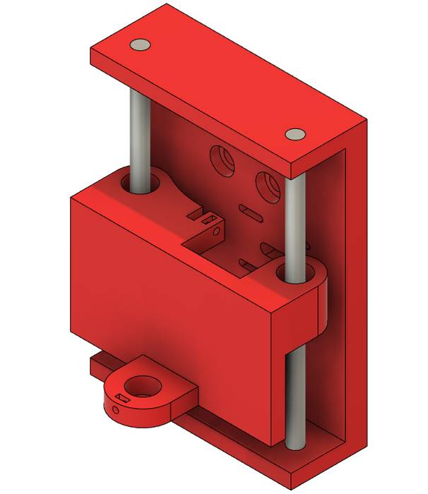
Then the motor was placed with a 10 teeth GT2 pulley.
The assembly up to this point looks like this.
Placed on the frame it looks like this.
Finally the pulley and belt system was placed.
Another individual contribution in this assignment was to prepare the controller with GRBL.
As a controller we used an Arduino UNO with a CNC Shield.
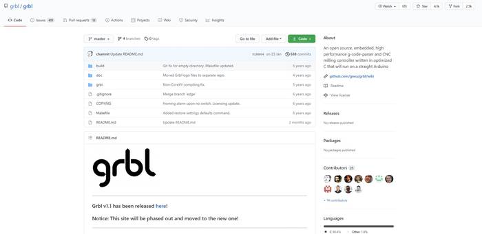
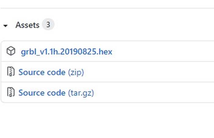
The first step in this process is to load the GRBL firmware on the arduino, for that you have to download it from the official Github repository.
Select the Source Code.
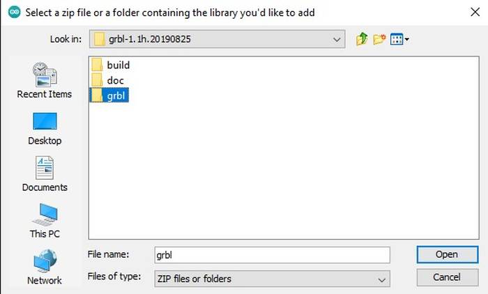
The next step is to add it as a library in the Arduino IDE.
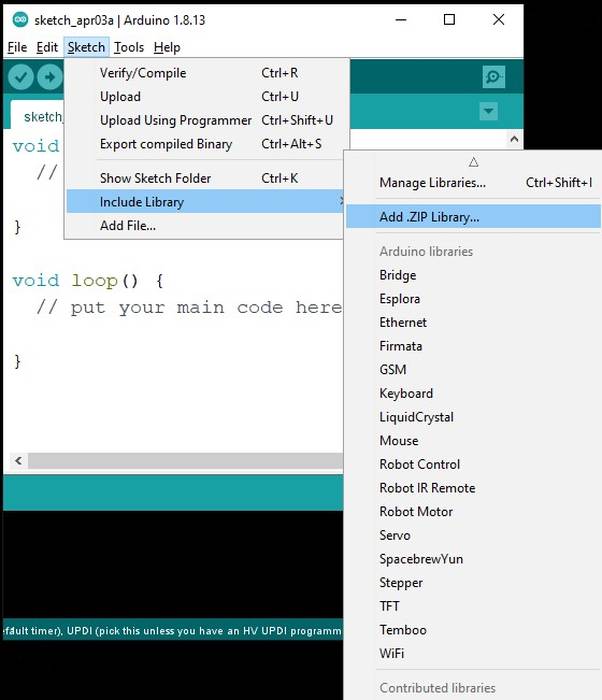
Select the "grbl" folder of the source code.
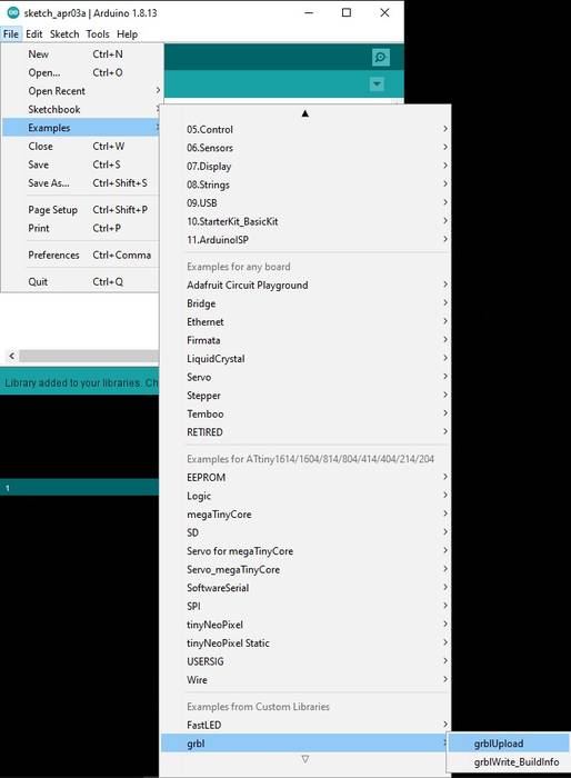
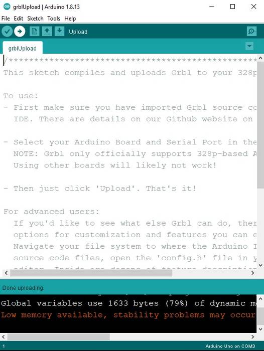
In the Arduino IDE go to the File->Examples->grbl->grblUpload option.
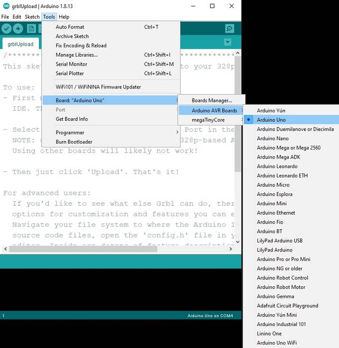
Connect the arduino to the computer and in Arduino IDE select "Board: Arduino UNO".
Of course you also have to select the port to which the Arduino UNO is connected.
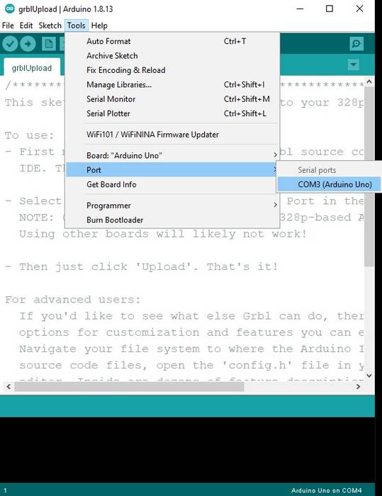
Finally just upload the firmware by pressing the Upload button in the Arduino IDE.
Another individual contribution I made for the assignment was the electrical connections of the whole machine.
For future reference on how everything should be connected I made a wiring diagram using Fritzing.
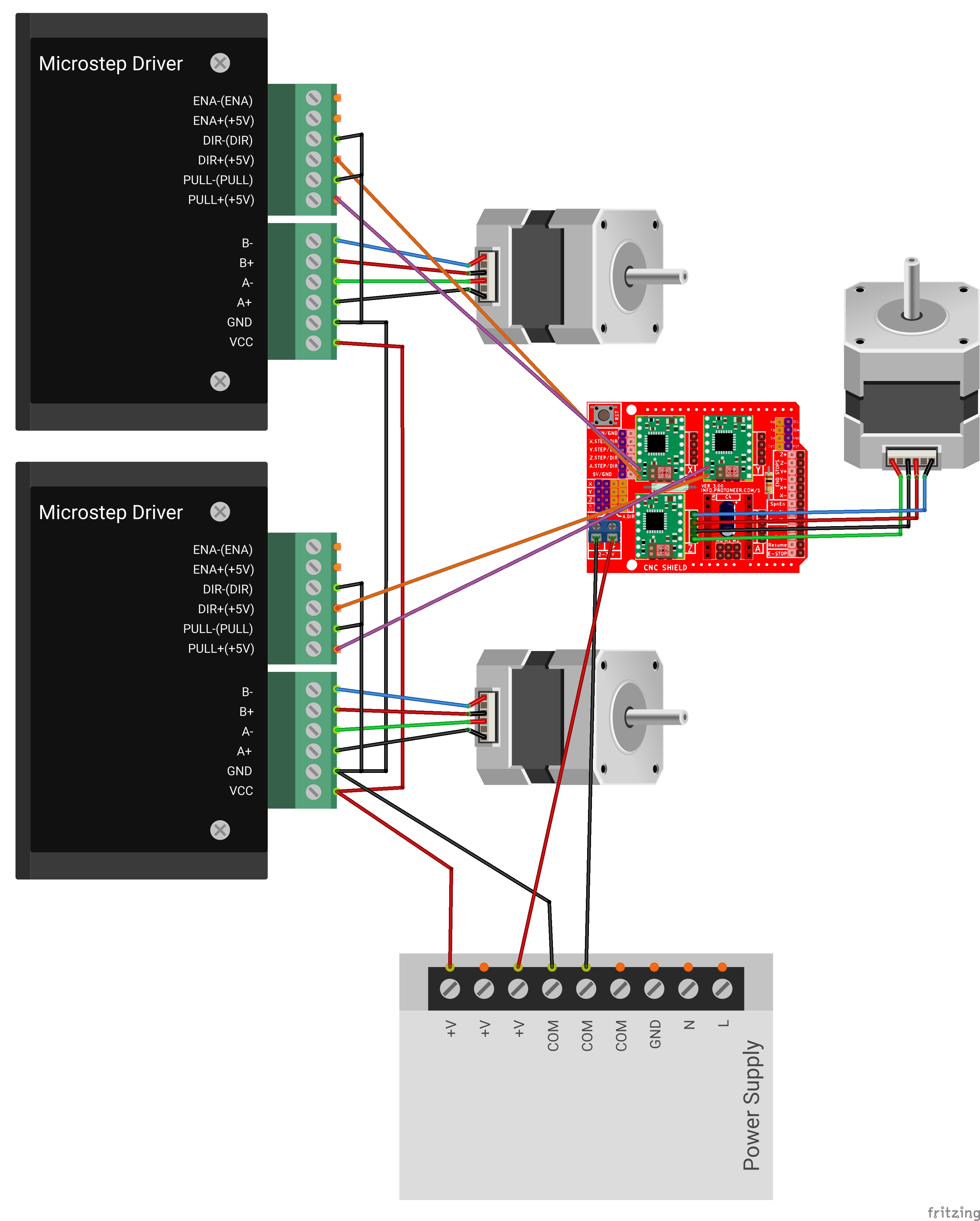
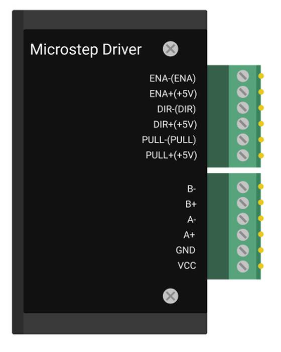
For this machine we are using TB6600 drivers which at the time of making the diagram (May 2021) are not available in any Fritzing library, I even searched the web if someone had already made them to import them but I did not find anything so I decided to make the Fritzing part myself.
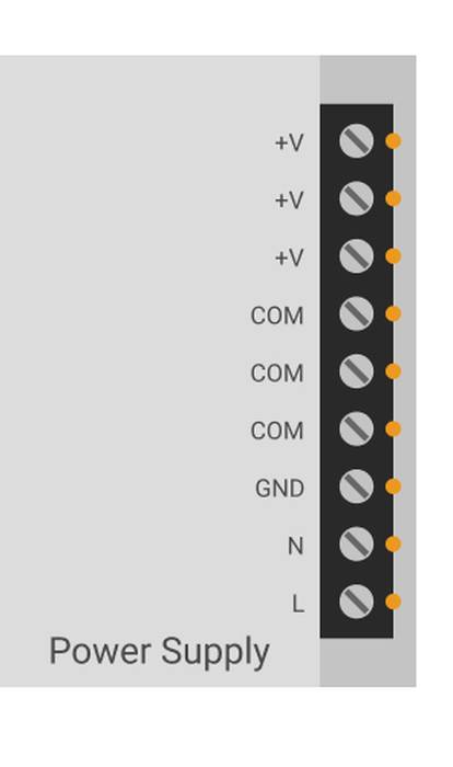
I also designed the power supply to place it in the diagram.
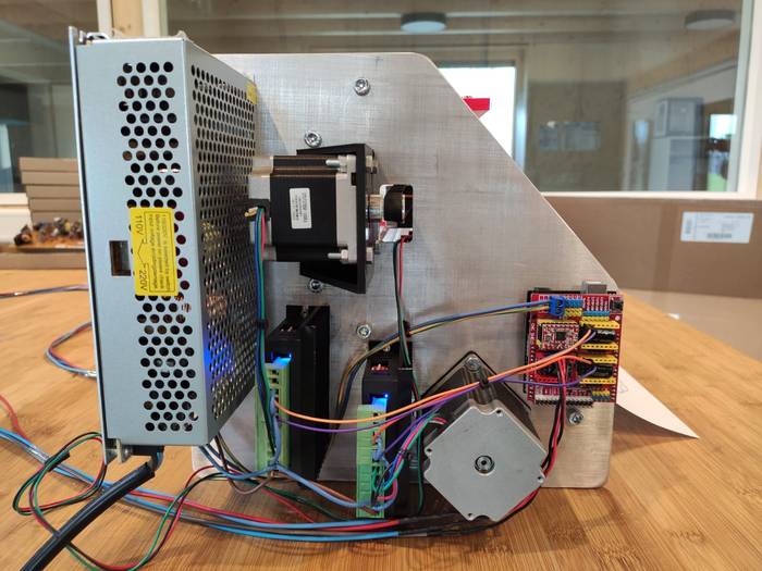
With the wiring diagram it was now easier to connect all the hardware. The result after wiring everything is as follows.
Link to Group Assignment page
More pictures about the machine