Electronics Production Group Assignment
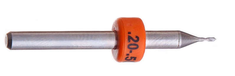
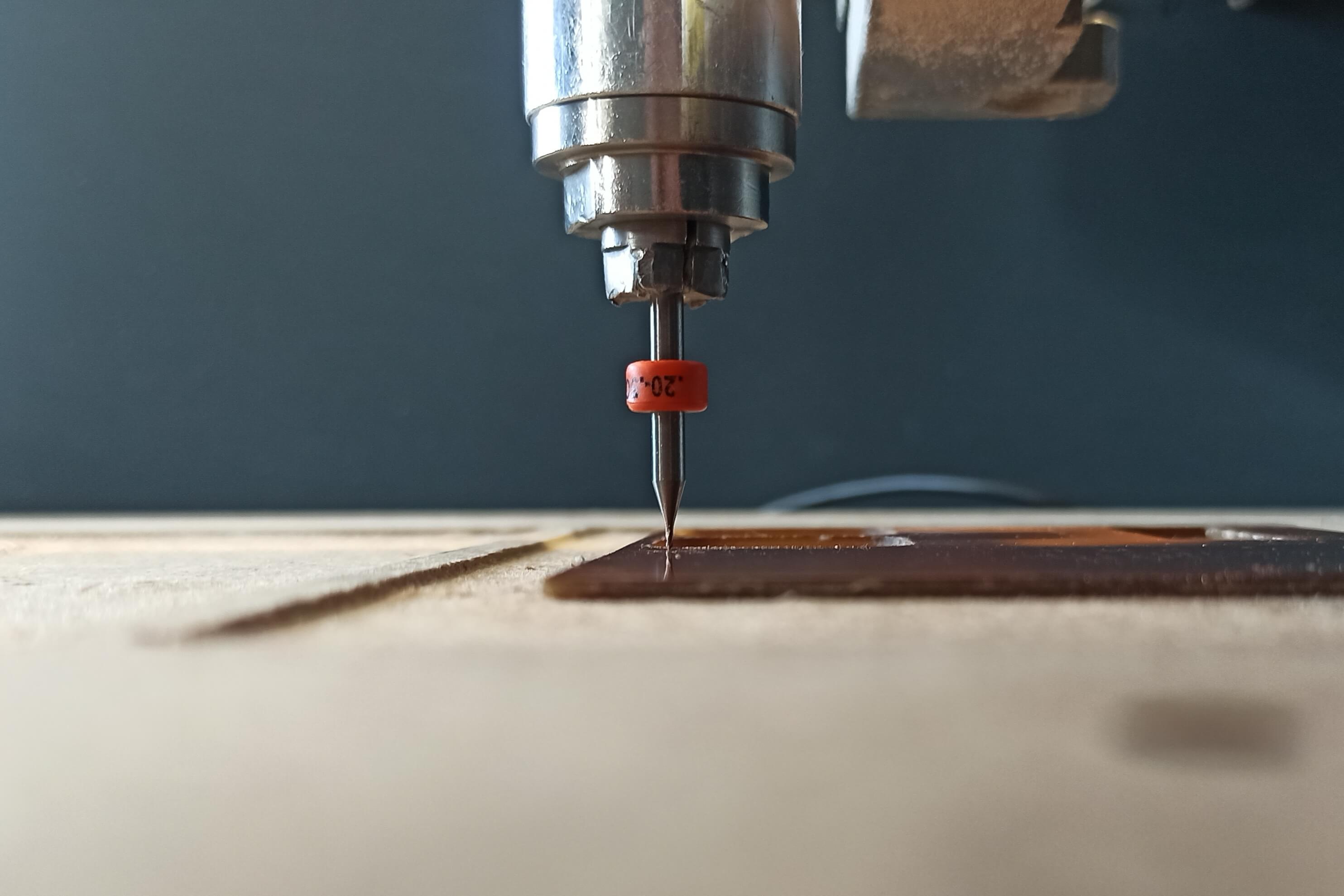
Inspired by the idea of one of my instructors (Ferdi) to produce high speed pcb's without tool changes I decided to experiment a bit with a 0.2-0.5 mm V-point tool.
The test parameters are as follows.
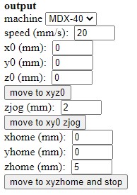
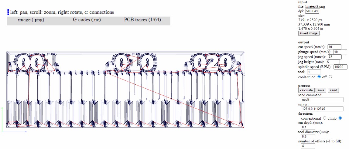
To make the traces: Output section
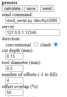
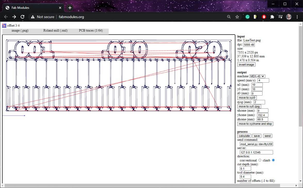
To make the traces: Process section
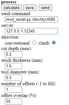
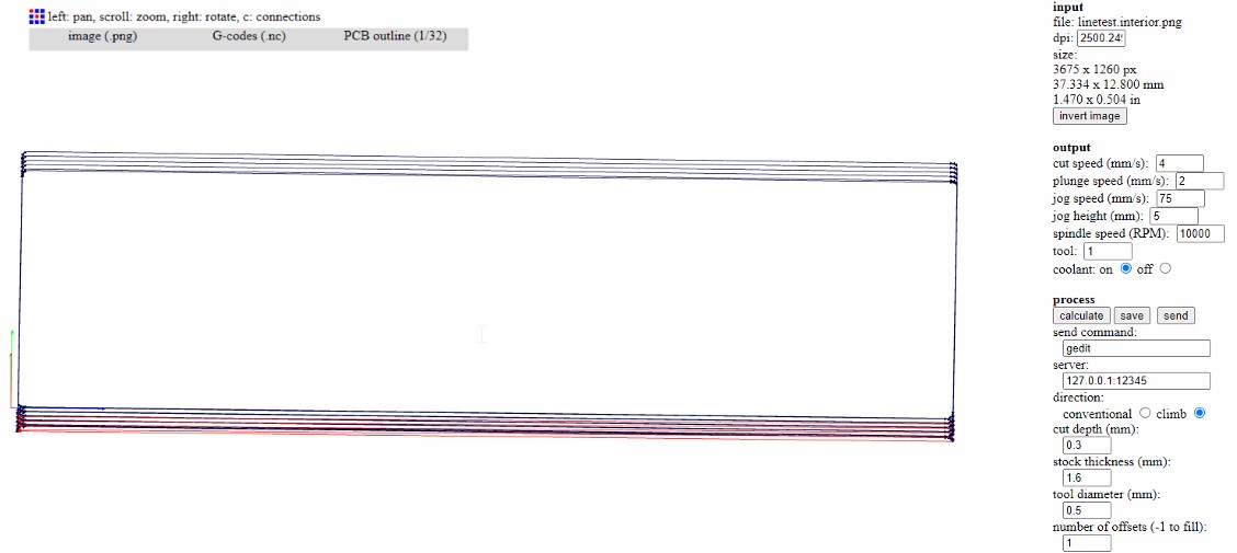
To make the outer cut I used the same parameters in the output section and only changed those in the process section.
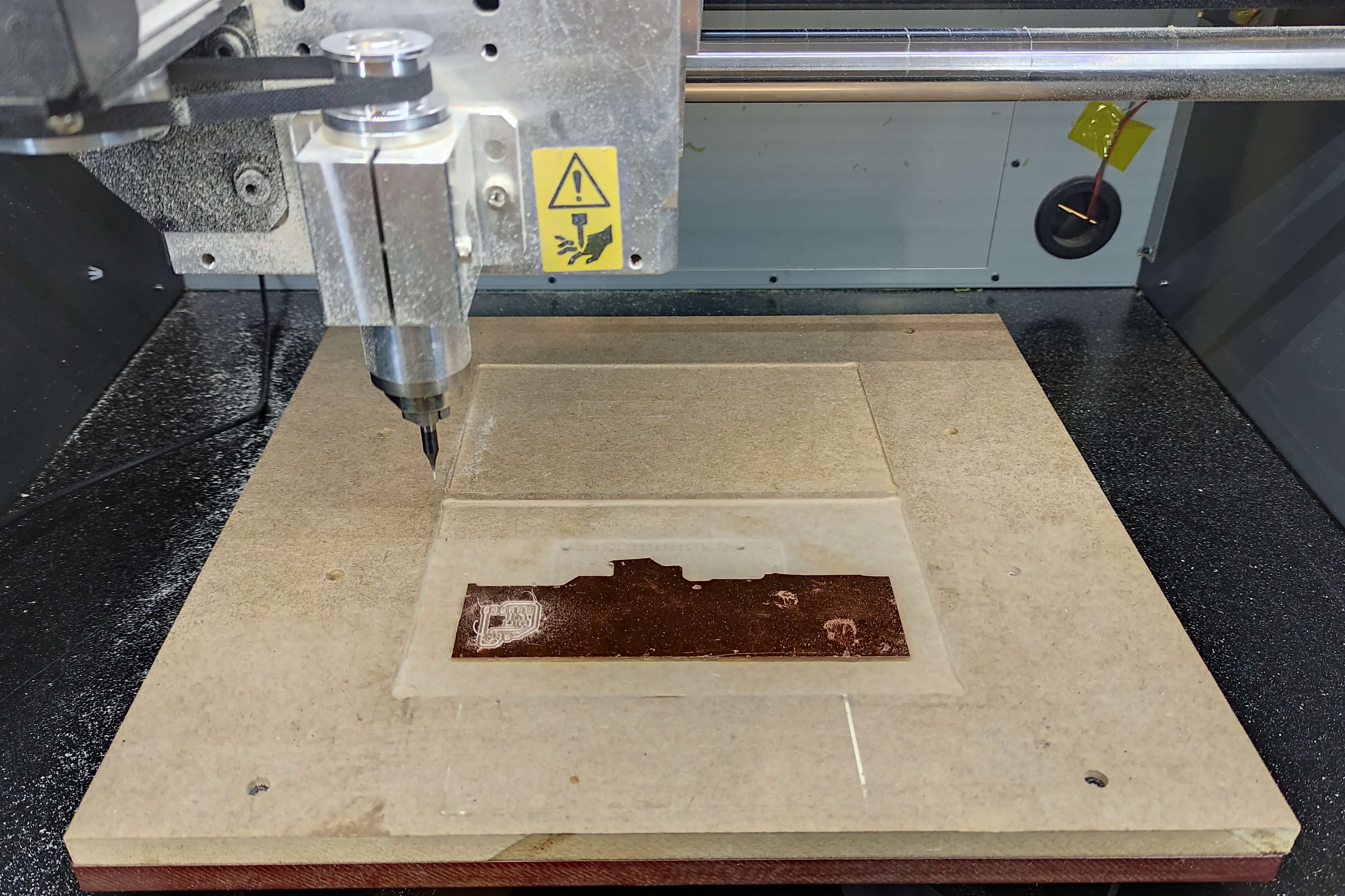
Here is a video of the milling process and the result.
The result is very promising but there is still room for improvement, more experiments will be done soon to better adjust the parameters.
Making process
It’s worth mentioning that there are three processes we do for a PCB:
- Traces
- Holes
- Outline
G-code generation
For it we used the FabModules - an only tool.
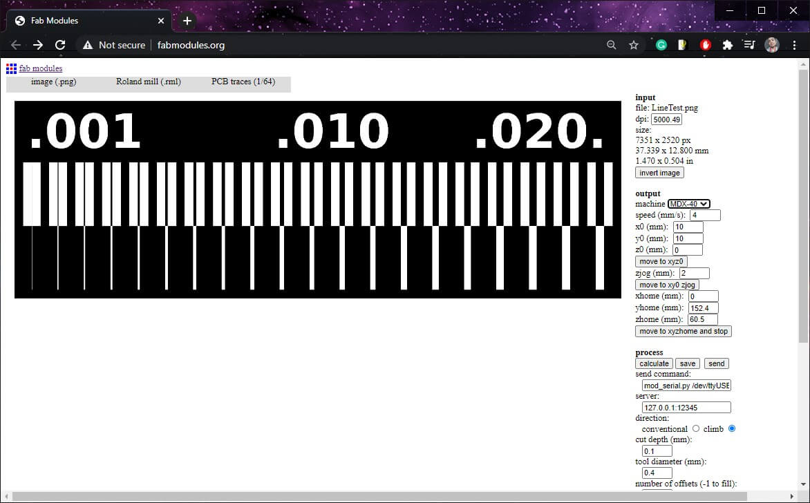
- input format > Select image.png > Select the image from the PC.
- output format > _Roland mill (.rml)
Output format is going to depend on the milling machine you have.
- process > Select process to configure.
For traces: PCB traces. For holes and outline: PCB outline.
- In output tab select machine to use.
- Fill in the text boxes.
- Press calculate.
- After that, press save.
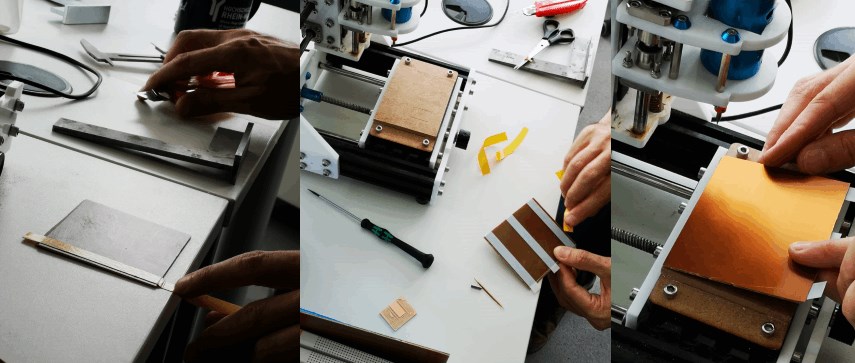
Mill process
Preparation
- Put the copper board on the of the machine.
- Put on the machine the appropriate Collect for the bit we are going to use (bit shafts come in different diameters).
- Put the bit on the collect and adjust it.
- Using the VPanel software, adjust the Home point.
XY will be the bottom-left corner of the board, Z axis will be when the bit slightly touches the board.
Ways to find the Z-0
-
Using Continuity of the multimeter, putting one tip on the bit and the other one on the board.
-
Using your hearing power:
- Start bit rotation.
- Slowly lower the tool until you hear a different sound (a soft milling).
-
Using your vision power:
- Start bit rotation.
- Slowly lower the tool until you an small amount of chip (a soft milling).
Milling machine
- Import the the Code in the VPanel.
- Press Output to start milling.
PCB done:
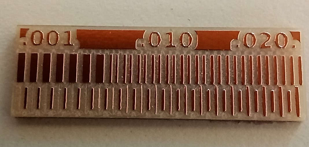
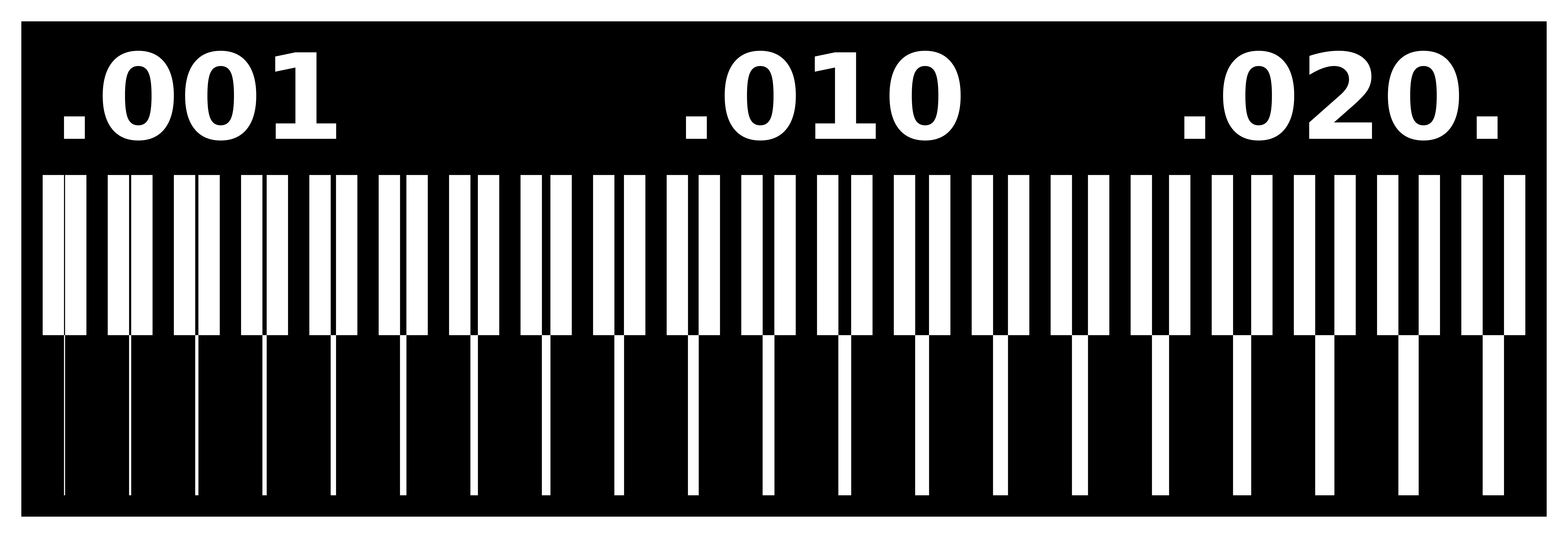
Test pieces
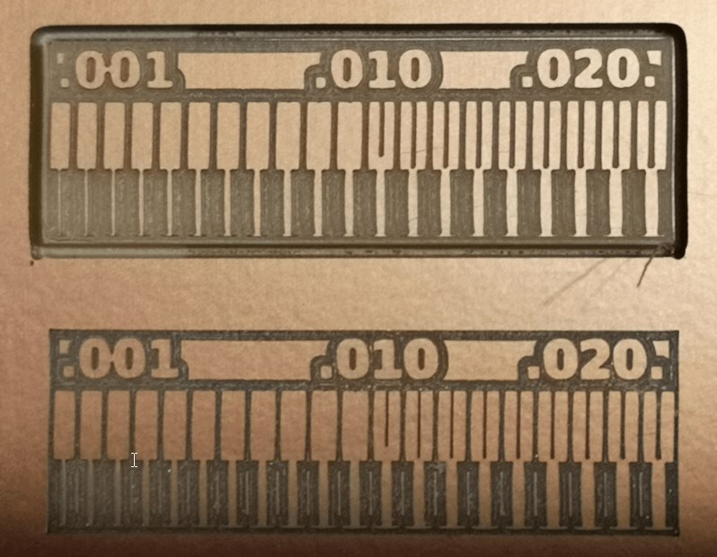
As usual it’s necessary to make a test beforehand; in this case with the end mills you’ll be using, a simple like the follow one let you know the trace thickness you can do, you can also determine the optimum cutting speed and spindle:
Images:
-
Traces:
-
Outline:

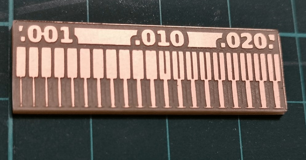
Test piece 1
End mills:
Traces: cylindrical 0.4mm
- Cutting speed: 2mm/s
- Spindle speed: 15,000RPM
- Cutting depth: 0.1mm
Cut: cylindrical 0.8mm
- Cutting speed: 4mm/s
- Spindle speed: 8000RPM
- Cutting depth: 0.6mm
Result:

Conclusions:
- Thinnest trace = 0.06mm
- Minimum clearance = 0.16mm
group
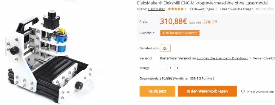
the machine
Buy the machine
Prepare the machine.
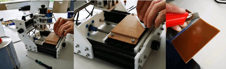
Test the machine.
We create the gcode in fabmoduleswith this settings,
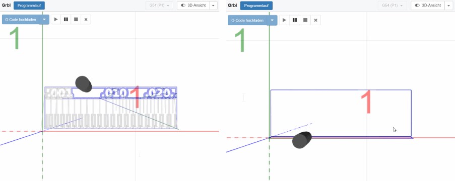
send it with cncjs to the machine
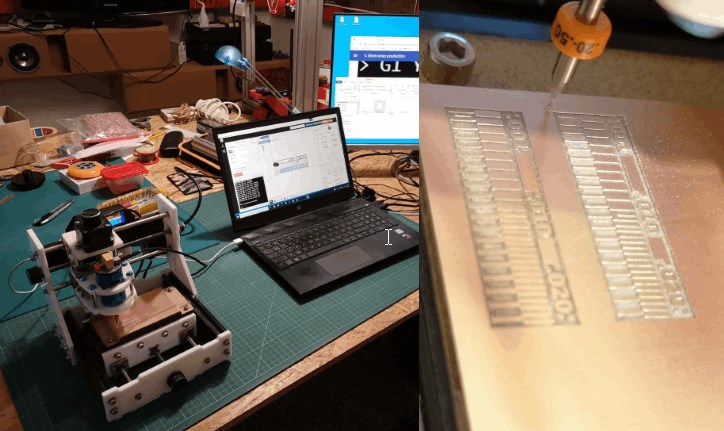
and get this result.