Machine: Modular CNC Machine (Plotter, Laser Engraver and Milling)
Introduction:
Almost all CNC machines have a single function per machine, despite that they may have the same design. In addition, the commercial solutions for a universal CNC machine are relatively expensive. In this project we will design and build an inexpensive CNC machine that could have many different attachments, all while controlled through a simple interface of G-code. The machine can perform milling and laser engraving operations. We wanted to build this CNC machine as a proof of concept while at the same time create something we could upgrade in the future.
The Design:
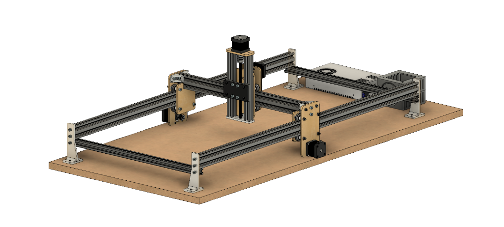
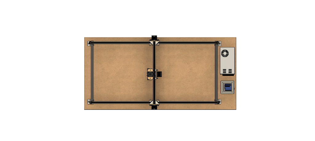
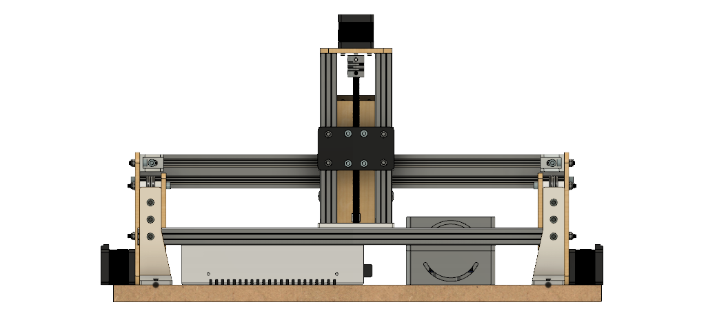
We used AutoDesk Fusion 360 to create my design. The area of travel for the cutting tool is 320 mm in the X, 830 mm in the Y and 120 mm in the Z, but this could be increased if longer aluminum extrusions were used. The work piece itself is fixed on the waste board below the machine. The gantry moves along the Y-axis via belt drive with motors on either side of the frame. The X-axis moves perpendicular to the Y-axis along the gantry, also via belt drive. Attached to the X-axis is the Z-axis, which moves up and down via screw drive. The overall design is similar to the X-Carve mixed with the Open Builds Acro laser cutting system. Again, the goal of the machine is to allow it to be upgraded later on. This means the extrusions can be scaled up or down to fit your needs and budget. We have also designed the Z-axis to have a basic attachment scheme, meaning multiple tools can be attached so long as an adapter is designed with matching mounting holes. For my purpose, we’ve created an attachment for the Dremel and 2.5W laser. You could also design an adapter for a pen or even a 3D printer head to name a few options.
Bill of Materials:
Frame; The aluminum extrusions all come from UGE Electronics, the frame is assembled together using small brackets and bolts, making it easy to adjust the geometry and make it larger if I wanted to in the future.
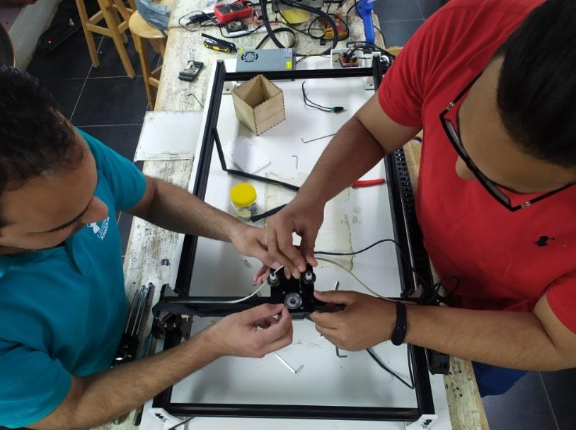
Carriages and Drivetrain; The X and Y axes move using carriages which reduce friction and make it easy for attaching the extrusions, motors, and other electronics. For the carriage plates, we chose to use laser cut acrylic and wood. The carriages also use V-slot wheels with bearings, which start to get costly as you add them up. However, we have found the wheels to work very well, and they increase the overall machine effectiveness. The motors on each carriage then use a belt drive system to move along the frame. For the Z-axis, we found it easiest to just design a carriage that would slide using the T-slots in the extrusions. The axis is also driven using a screw and nut directly attached to the motor.
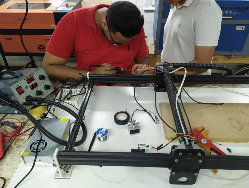
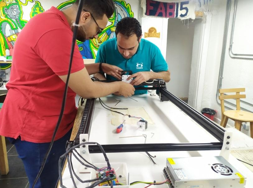
Electronics; Based on researching other CNC designs and machines that are sold online, we decided to go with an Arduino Uno as the brains. We purchased 4 stepper motors, 4 motor drivers and 3 limit switches. There is a heat sink for each stepper driver, however we found they still got pretty warm. We added on a cheap computer fan, powered by the Arduino, and this works pretty well to keep the temperature down.
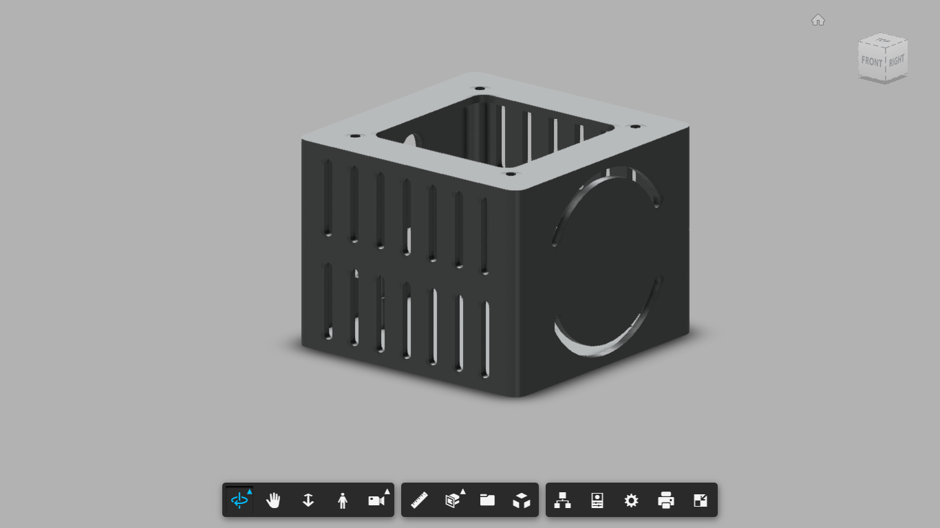
Custom Parts; We used the Laser Cutting M/C and 3D Printers to fabricate some parts. The laser M/C is MORN MT3050D and the 3D Printer is Prusa I3 MK3.
See attached files for all .STL, .STP and .dxf files for all parts and also an Excel file for all parts, prices and links.
Tools Needed and Parts Preparation:
Tools Needed
One of the main goals for this project was to create the CNC machine by using the least amount of tools possible. This does increase the cost in some places, however the majority of the tools needed are pretty basic or readily available. Here’s what we used;
Drill
Allen wrench set
3D Printer (Prusa I3 MK3)
Hot glue gun
Digital Multimeter
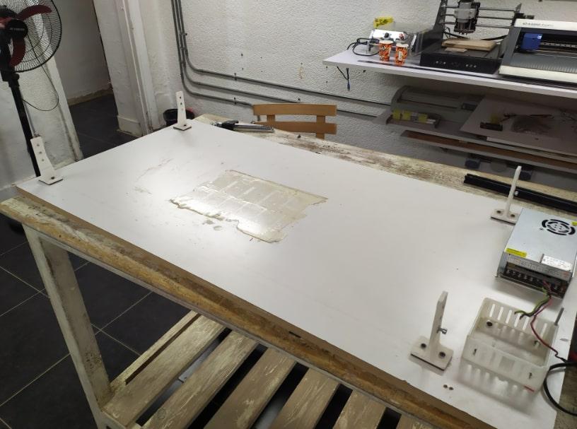
Parts Preparation
A few parts will need to be prepared in order to fully fit for the machine.
All 3D printed parts should be cleaned of all supports. Some holes may need to be enlarged/test fit to make for easy assembly later on.
The waste board will need to be prepared since it shows where the frame will attach later on.
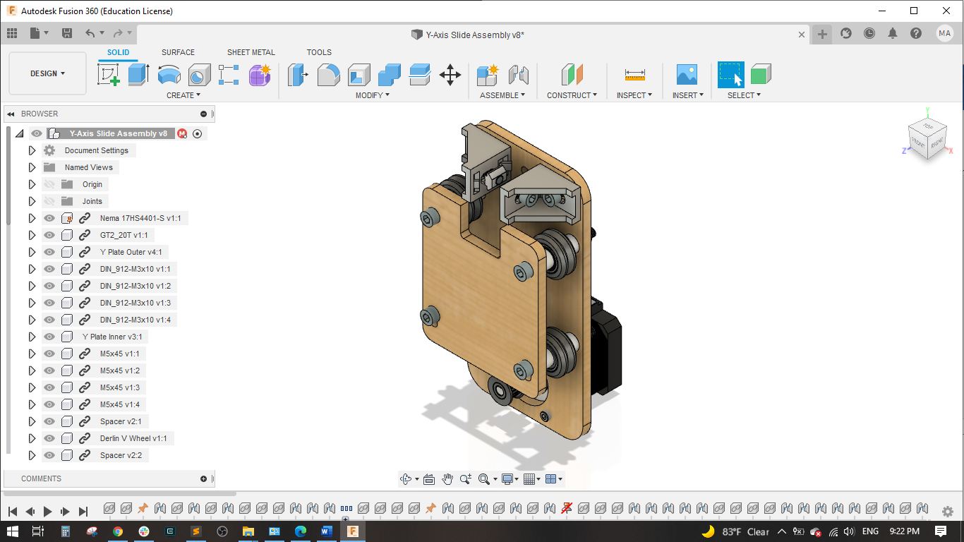
Y-Axis Slide Assembly:
Attach a NEMA 17 motor to Y Plate Outer using (4) M3 x 10mm Bolts. Attach the Belt Pulley to the motor shaft.
Assembly (4) M5 x 45mm Bolts through Y Plate Inner. Put (1) Spacer, (1) Delrin Wheel and (1) Spacer on the other end of the bolts.
Attach the assemblies from Steps 1 and 2 using (4) M5 Locknuts. These will be tightened further later on so the wheels ride freely on the extrusions.
Use (2) M5 x 16 mm bolt and (2) T-Slot Nuts to attach (2) Small Brackets.
Use (2) M5 x 10 mm bolt and T-Slot Nuts for the other bracket openings.
Repeat these steps so you have two assemblies.
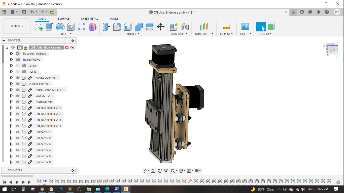
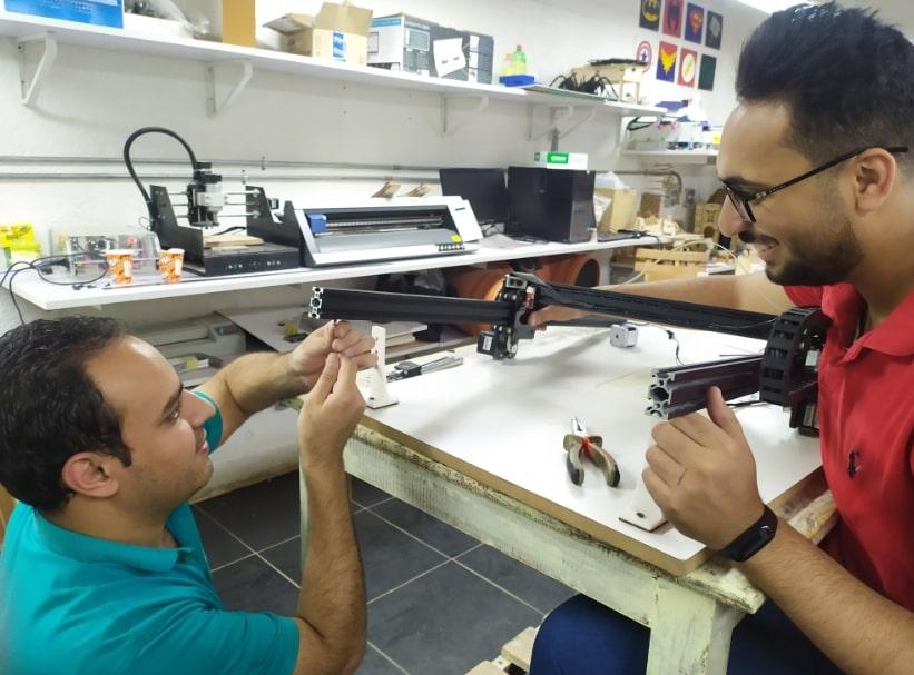
X/Z-Axis Slide Assembly:
Assembly (4) M5 x 45mm Bolts through (1) Spacer, (1) Delrin Wheel and (1) Spacer and into X Plate Inner.
Assembly (5) M5 x 13mm through the assembly from Step 1 and fasten T-Slot Nuts to the other side. These will be tightened later.
Attach (1) NEMA 17 motor to X Plate Inner using (4) M3 x 10mm Bolts. Attach the Belt Pulley to the motor shaft.
Attach the assemblies from Steps 2 and 3 using (4) M5 Locknuts. These will be tightened further later on so the wheels ride freely on the extrusions.
Attach (1) NEMA 17 motor to Z Plate using (4) M3 x 10mm Bolts. Attach one end of the 5mm to 8mm Coupler to the motor shaft and the other to the 8mm Threaded Rod. Put the Lead Screw Nut through the Z Slide and thread onto the rod.
Slide (2) Linear Slide Bearing Profiles into (2) 2020 x 200 mm Extrusions. Attach to the assembly from Step 5 using (2) M5 x 16 mm bolts. Make sure the Z Slide slides into the extrusion slots.
Attach the Adapter to the Z Slide using (4) M5 x 16 mm and T-Slot Nuts. Use (4) M5 x 13 mm to attach the Adapter to the Linear Slide Bearing Profiles.
Slide the assembly from Step 4 onto the assembly from Step 7. Attach Z Bottom Rod Hold to the bottom of the extrusions using (2) M5 x 16 mm bolts.
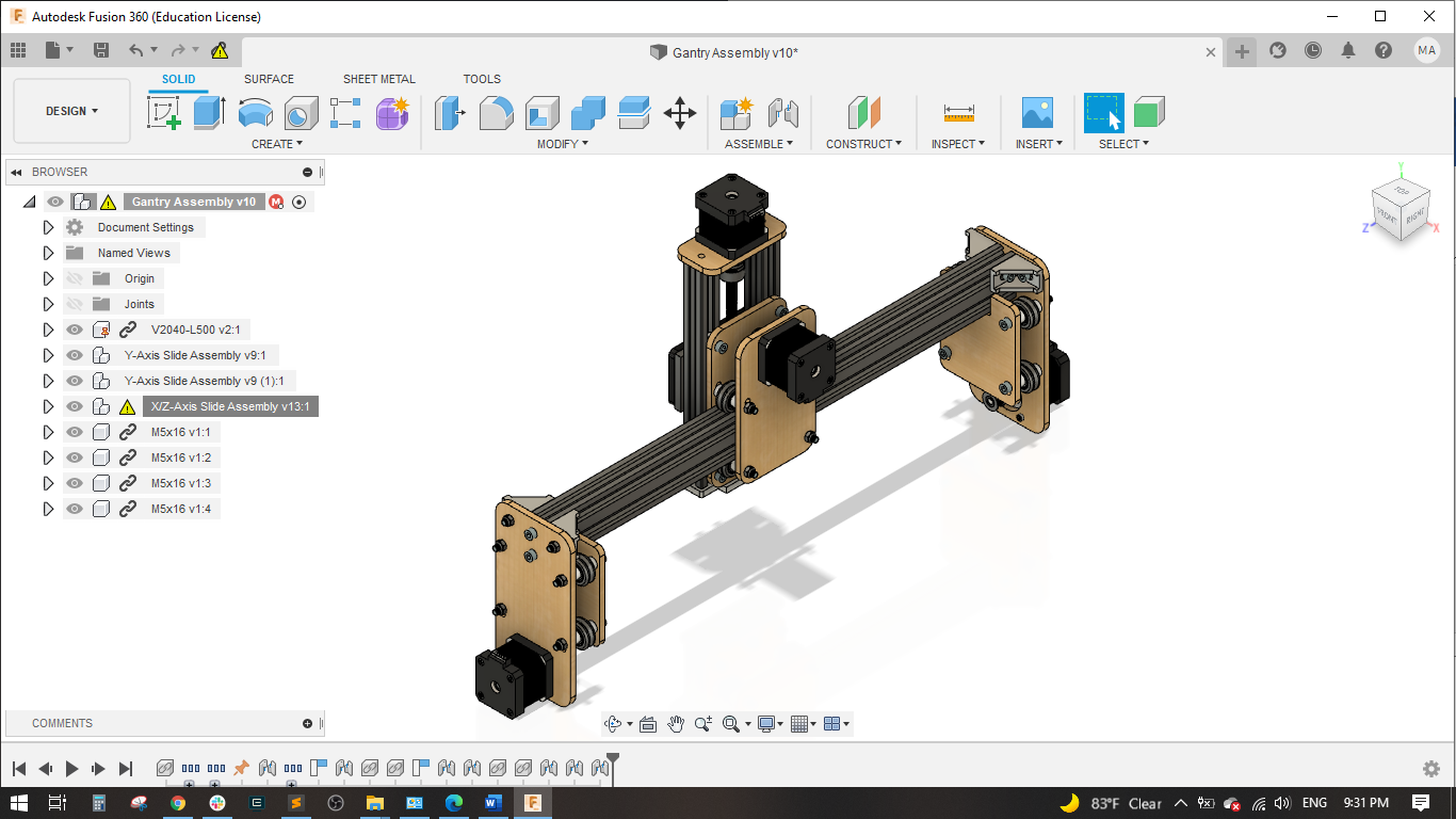
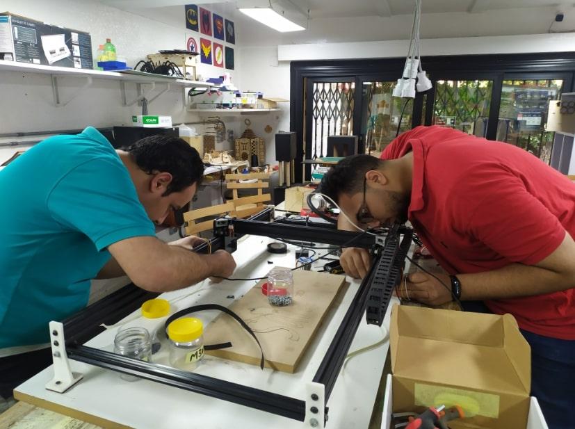
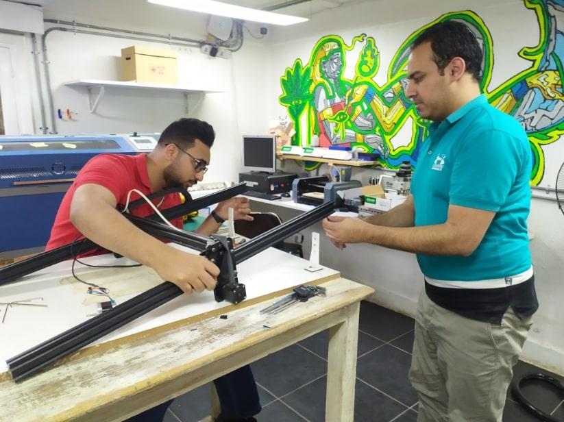
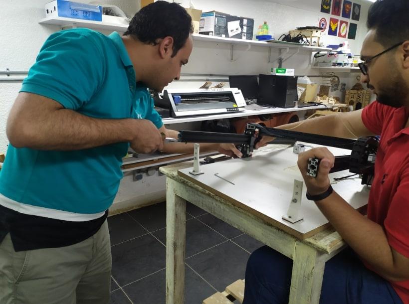
Gantry Assembly:
Slide the 55 cm Belt into the 2040 x 500 mm so it lays in the extrusion slot. Slide in (1) M5 x 10 mm bolt with T-Slot Nut and tighten near the end. One end of the belt is now fixed.
Slide the X/Z Slide Assembly onto the extrusion and loop the belt so it goes under the wheels but around the belt pulley. Adjust the wheels so the extrusion moves freely but doesn’t wiggle too much. The belt should be aligned in the middle of the belt pulley.
Slide in (1) M5 x 10 mm bolt with T-Slot Nut and tighten near the other end. Adjust as necessary so the belt is properly tensioned and the motor moves as the slide is pushed back and forth.
Slide in Y Slide Assemblies to either end of the extrusion. Use (2) additional 0.25” Cap Screws on either end and tighten the preexisting bolts in the small bracket.
Make sure all bolts are tightened and the belt runs smoothly for the X/Z Slide Assembly.
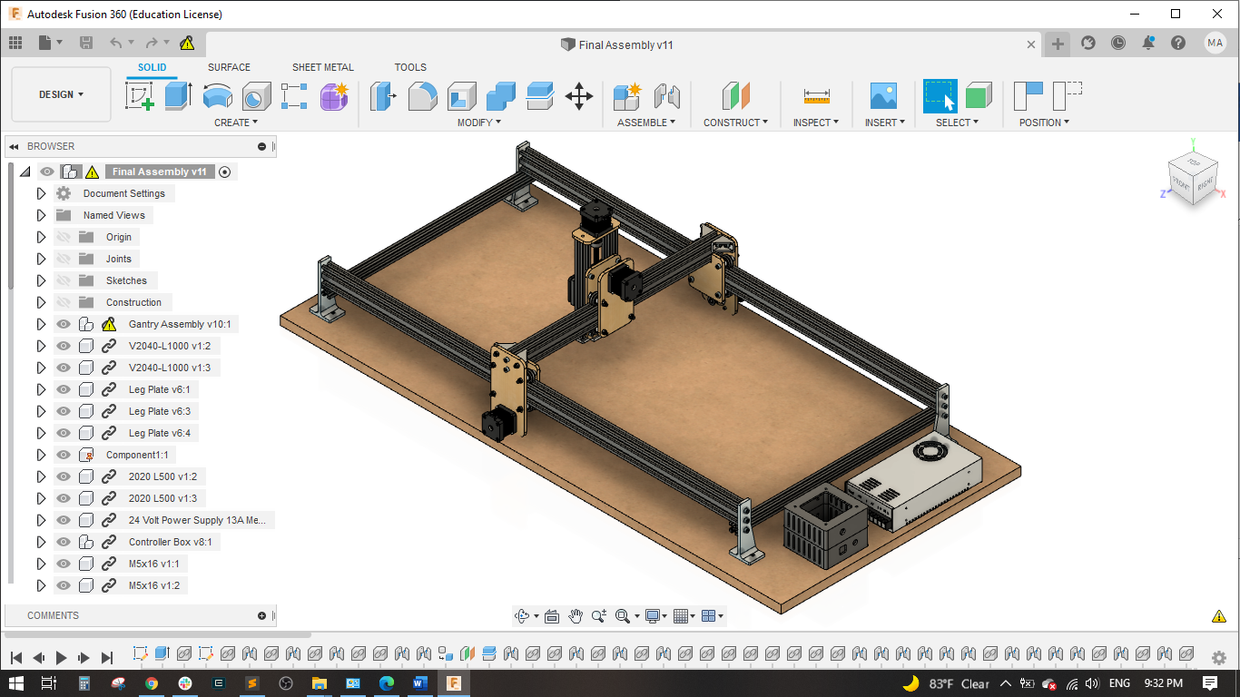
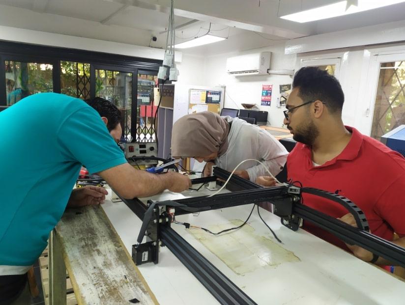
Final Assembly:
Attach (4) Leg Plates to the Waste board using (2) #6 x 1/2” Screws for each leg. Make sure they’re all squared and perpendicular to the edges.
Slide the 1050 mm Belt into the 2040 x 1000 mm so it lays in the extrusion slot. Slide in (1) M5 x 10 mm bolt with T-Slot Nut and tighten about 4 mm away from the end. One end of the belt is now fixed. Repeat for the second extrusion.
Slide the Gantry Assembly onto the extrusion and loop the belt so it goes under the wheels but around the belt pulley. Adjust the wheels so the extrusion moves freely but doesn’t wiggle too much. The belt should be aligned in the middle of the belt pulley.
Slide in (1) M5 x 10 mm bolt with T-Slot Nut into both extrusions and tighten about 4 mm away from the other end. Adjust as necessary so the belt is properly tensioned and the motor moves as the gantry is pushed back and forth.
Slide the assembly from Step 4 into place between the legs on the waste board. Use (2) M5 x 16 mm bolt on each leg to attach the leg to the extrusions. Place (1) M5 x 13 mm bolt and T-Slot Nut through the bottom leg holes. Do not fully tighten.
Slide (2) 2020 x 500 mm Extrusions onto the bottom T-Slot Nuts and tighten once in place.
Make sure the slides move freely and engage the belts. Check to make sure the frame is square and tighten all bolts.