Week 12 : Output Devices
☛ Individual Assignment
☐ 1. Add an output device to a microcontroller board you've designed, and program it to do something
☛ Group Assignment
☐ 2. Measure the power consumption of an output device
☛ Group Assignment
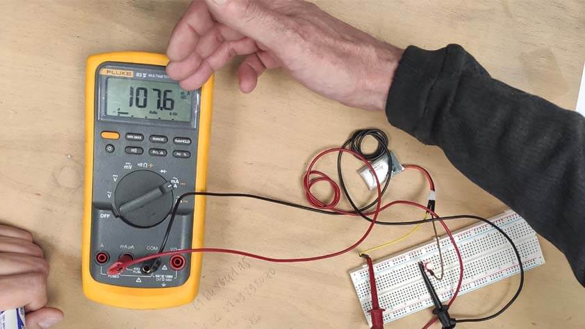
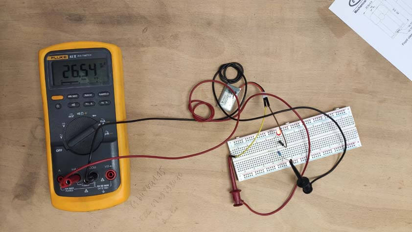
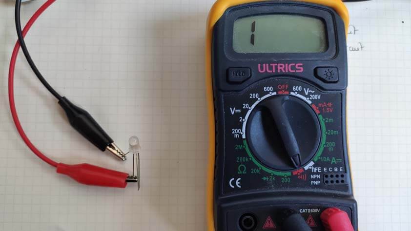
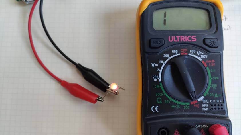
During the group assignment we used the multimeter to measure the electrical consumption of a LED with and without a resistor. On the images below we can see that it takes more energy when the current is not regulated by the resistor.
Here is our setup to measure the power consumption with the Keithley DMM7510, a bigger multimeter.
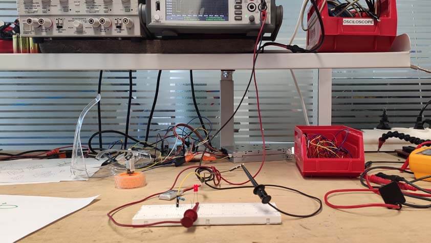
This multimeter which is more powerful allowed used to visualize the power consumption through time, and with a great precision.
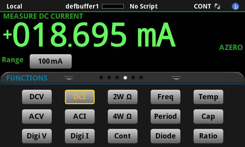
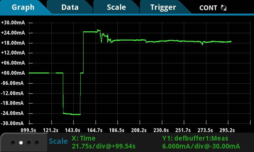
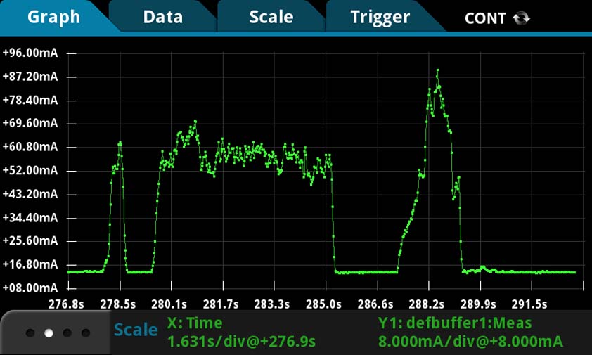
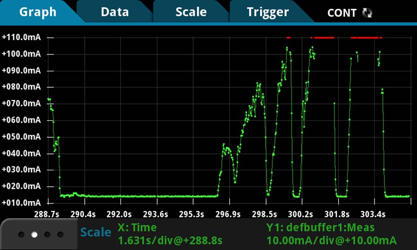
We used the Keithley DMM7510 to visualize the power consumption of a 12V dc motor.
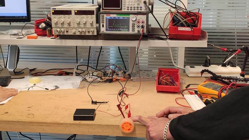
We applied resistance to the wheel attached to the motor, it created peaks in the power consumption as it has to "work harder".
Here are the screenshots where we can the those consumption peaks :
☛ Testing LEDs
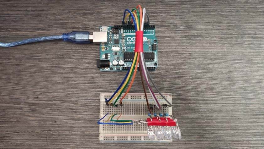
I tested several output devices, I began by LEDs.
▸ RGB LED
My first try was with a RGB LED, this link was useful to start : How do RGB LEDs works. To begin, I used the multimeter in contonuity mode to check if my RGB LED was with a common anode or with a common cathode : I have common cathodes RGB LEDs.
I followed a tutorial to control the colors of an RGB LED with a joystick as I need to practice with the joystick for my final project, there it is : Tutorial to control a RGB LED using a joystick.
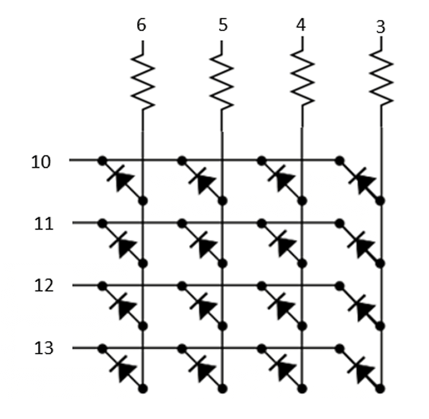
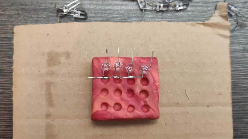
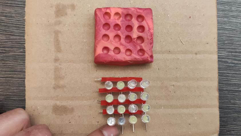
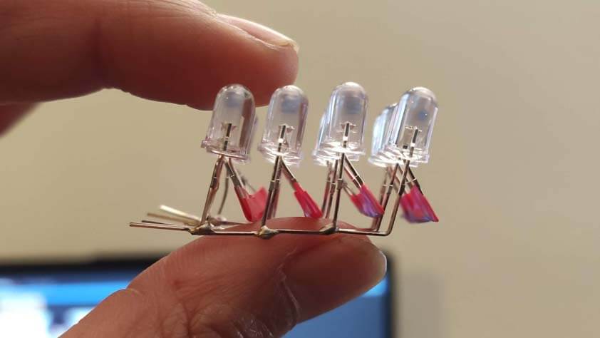
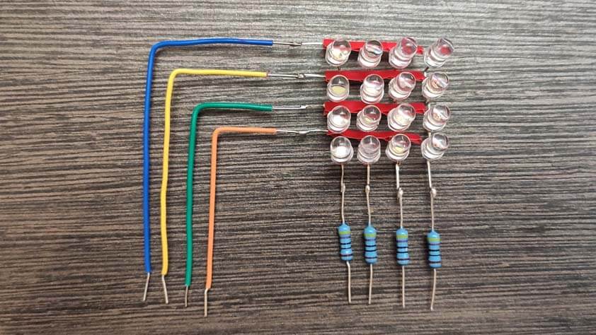
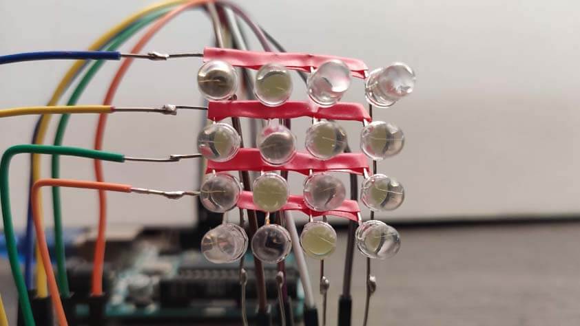
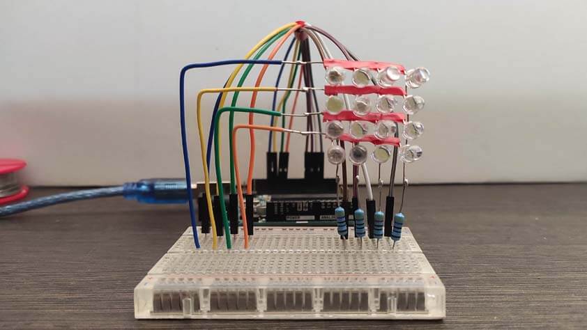
▸ DIY LED Matrix
I have always been interested in these kind of matrix, I didn't know it was so easy to make, so using the following diagram and this tutorial : (Quick) Tutorial for a 4x4 LED matrice.
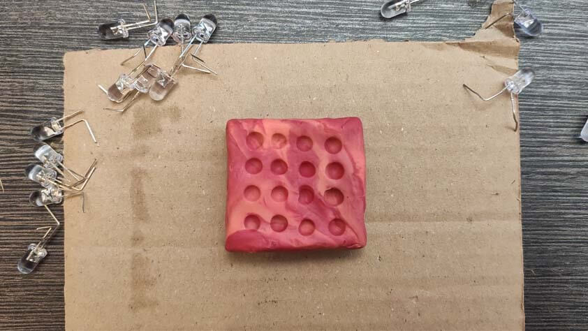
I needed a something to maintain the LEDs for soldering them in an ordered manner, I had clay and it was perfect for this job. I bended each LED pins in order to use those to structure the matrix.
Here is the code I use in the video :
What is cool about this thing is that I can use it to practice for loops !
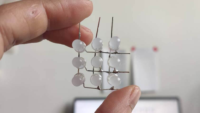
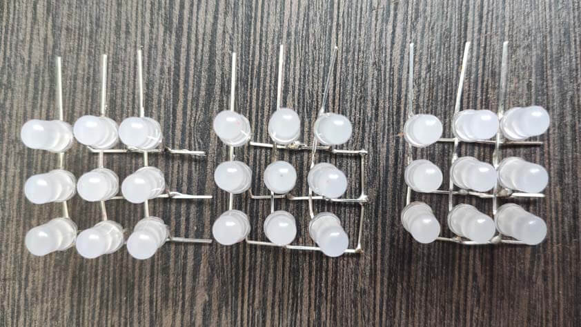
▸ DIY 3*3 LED Cube (with a non-cubic shape)
this video inspired me to make a cube made of LEDs, I prepared and soldered three matrix of 3*3 LEDs and I had to find how to assemble the trhee layers, it did not look like a cube at the end, but the result is cool anyway. I was missing time a found a code to light the LEDs randomly on this PDF file Here I found the code to light LEDs randomly.
ANd here is another tool for me to practice for loops and LED displays.
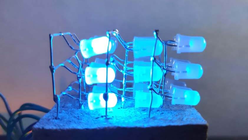
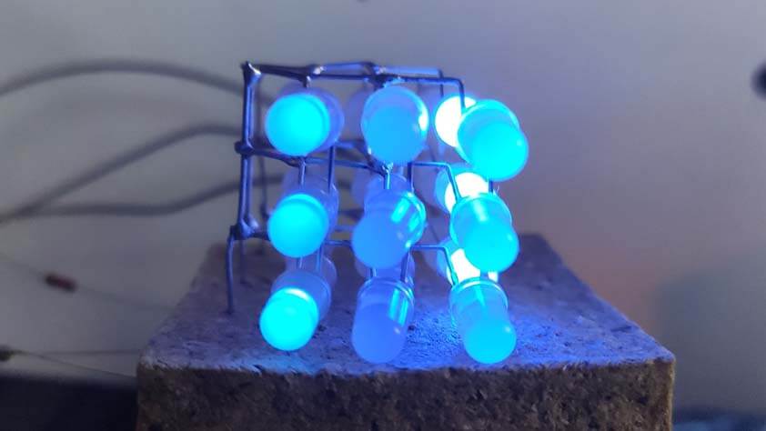
This is a video of the code running, I must have miss somthing as complete columns are lit and not singles LEDs.
▸ Inductive Charging Set
We have this Adafruit Inductive Charging Set 5V, this is a very handy thing as it does not need any code to work, both parts has to be power supplied and the magnetic field acts.
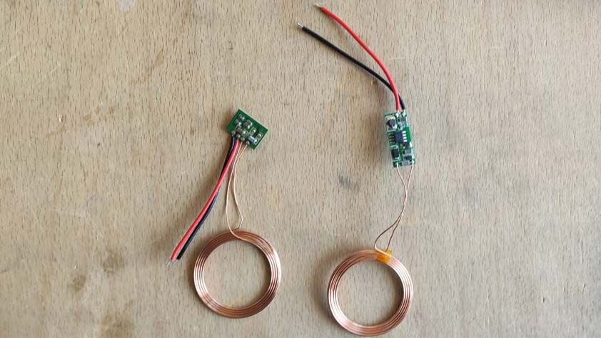
Here is a video of the inductive set working, the LEDS are turning when both parts are close.
☛ Testing Motors
I tested dc gearmotors and servo motors :
▸ Servo Motor
First, I used a servo motor alone, using this link as a reminder Adafruit lesson about Servo motors, the video following is a test with a servo motor.
▸ DC motors
I used a L293D motor driver to control two dc motors : A useful link regarding the L293D used as a motor driver
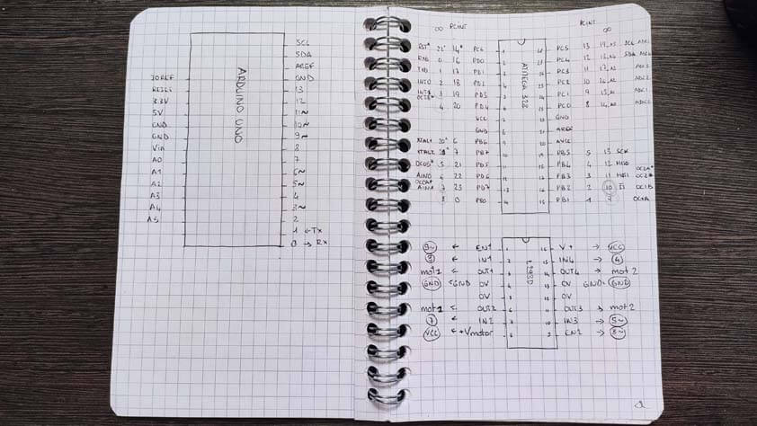
Next, I made a circuit composed of 2 dc motors, and a servo motor. Such a board is what I need for the drawing car of my final project. The image below is a sketch of the board I'am using and their pins. As I worked on an Arduino Uno, I need to "translate" my pins to the AtMega328p pins.
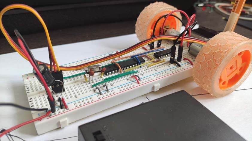
Here is the final circuit :
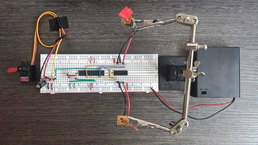
Here is the final circuit working, I am using a 6V power supply, it is not enough for the motors, but is works as a demonstration :
I upgraded the breadboard with orange wheels and taped a pen to the servo motor, let me present you the Drawing breadboard :
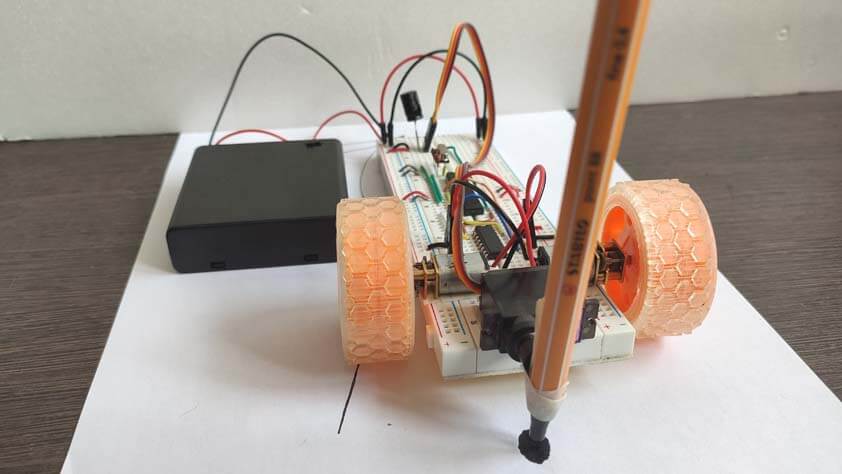
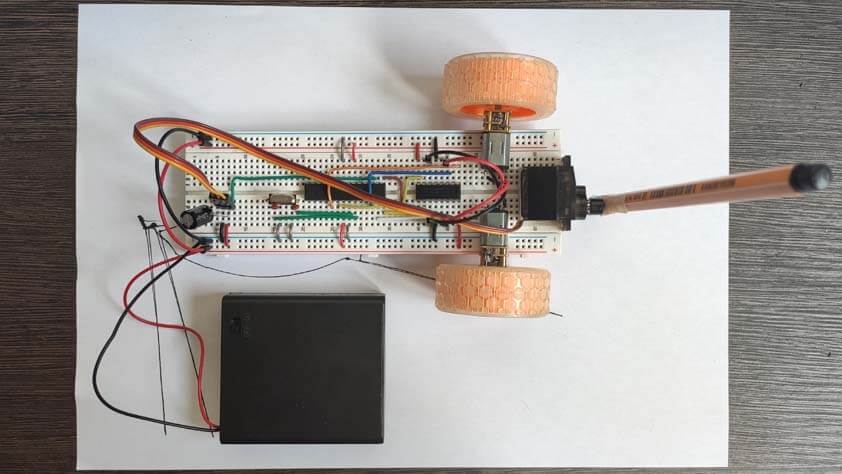
Here it is moving :
☛ Making the PCB for the Drawing Car
This part is updated and published on June, 1st.
▸ PCB design using Eagle
I designed a board for the drawing car, by using the circuits I made on breadboard and translating these into a PCB, by using EAGLE. I forgot importants component in my first attempt, such as a resistor for the rest pin, and capacitors for the microcontroller. Following Jonah's advices, I added other components to secure the board polarity.
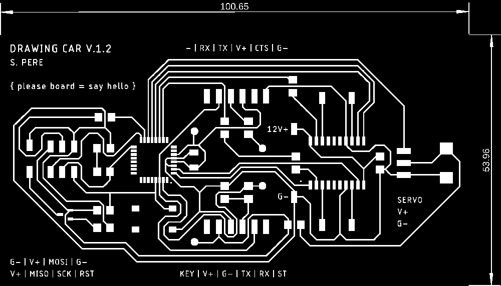
Here is the final circuit schematics for the drawing car, I use several 0 Ohm resistors as jumpers.

▸ Lasercutting & Soldering
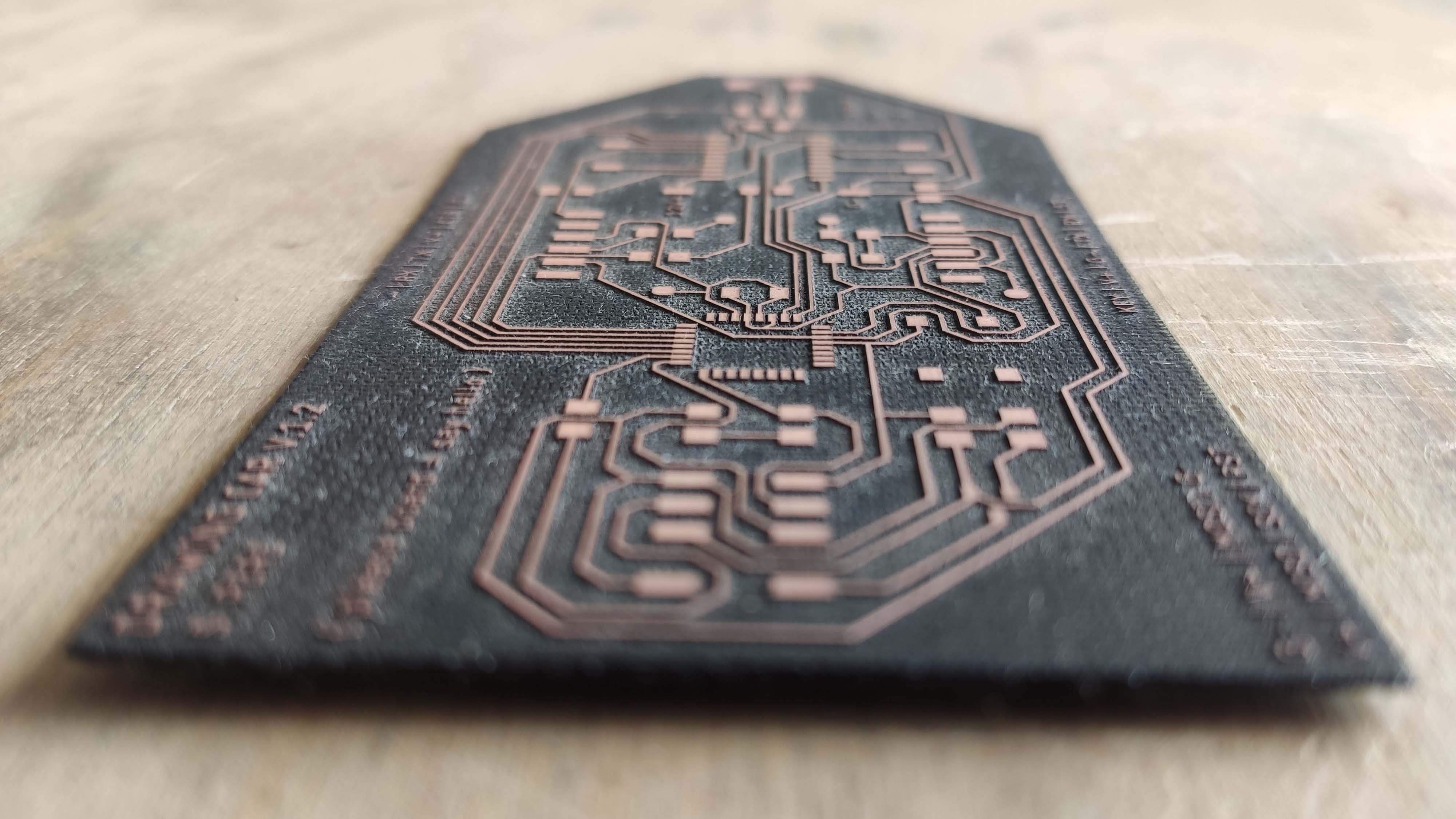
Here is the laser cutted board for the drawing car, using what I learned from my previous errors in the PCB making process, this board came out well !
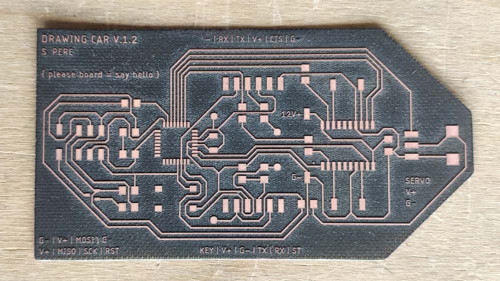
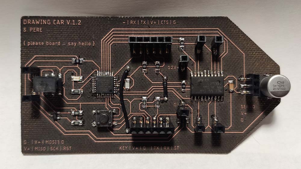
After checking the board with a multimeter I could solder it, and here is the result.
▸ Programming and testing
In order to make it work, I wrote a kind of incantation on the board.
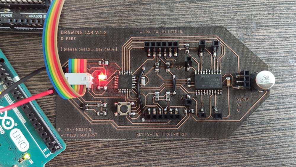
Then I used the Arduino IDE to program it, by using an Arduino as an ISP, and a second Arduino to power the Drawing Car board. I compiled the Blynk example program on it, and it worked !
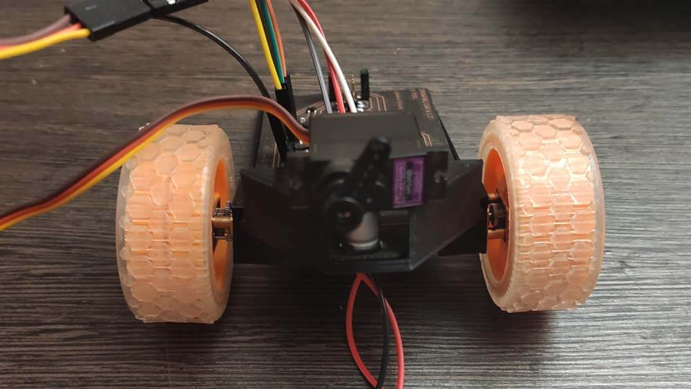
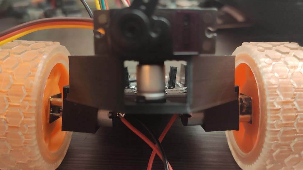
In order to test the motor I designed motors and servo motors holder integrating the board.
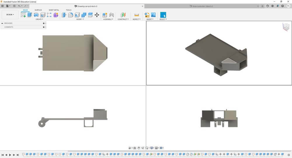
This step is useful, the board is much bigger than I expected and my original design is not adapted anymore. I Also need to integrat a system to lift-up the pen.
I uploaded a code to control the motors in one direction at a time, but unexpectedly, the motors are only moving in one way, as if the motor driver wasn't doing anything. Like shown on the video below.
I uploaded the code to control the car with the controller, through the HC-05 bluetooth module, in this configuration the motors are actually being controlled. What is unexpected here is that one motor is only turning forward. Here is the video :
Here is the code I use to (try to) control the motors in the first video : The second video uses the teacher-students codes I wrote in week 12.
▸ Drawing Car board files (zipped)
The board working is displayed in the next week, Networks and Communication.
☛ Making the PCB for the Labyrinth
I also designed a board to control two servo motors.
▸ PCB design using Eagle
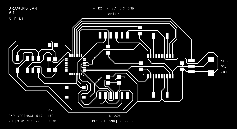
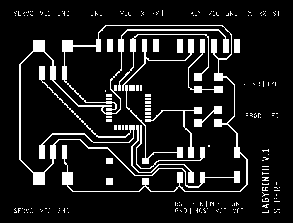
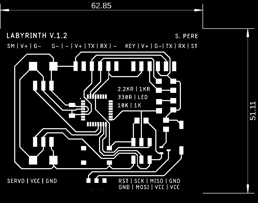
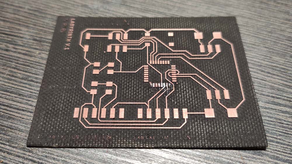
Here are the traces of the board, as for the Drawing Car, my first attempt is missing important components, the second image is more complete.
Here are the schematics for the Labyrinth board :

▸ Lasercutting & Soldering
In my first attempt in soldering, with my own solder iron, the one with a big tip and with a temperature that is not totally reliable, I burnt the traces, causing them to go off the board.
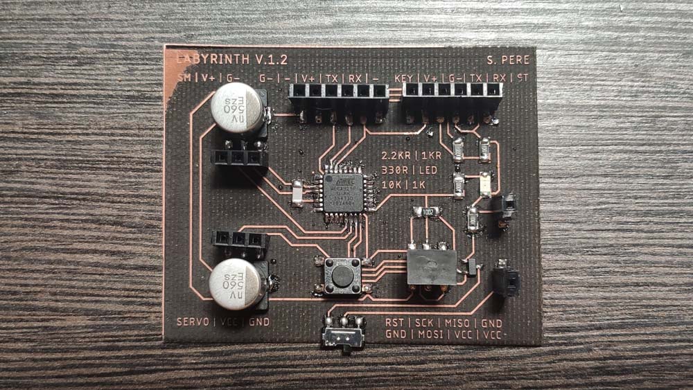
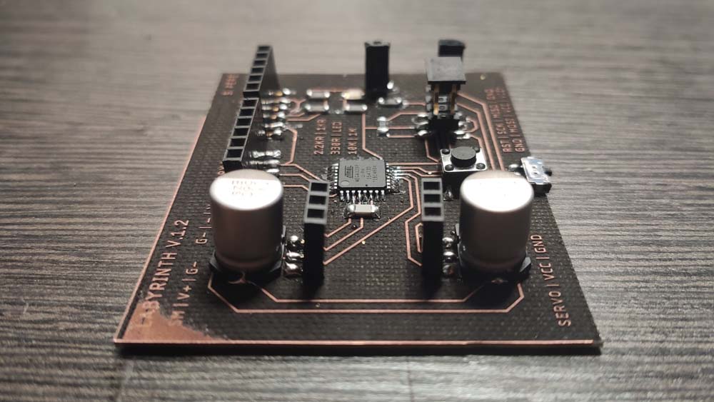
I lasercutted it again, this time the FR4 material was not totally plane so a corner is not totally engraved. Nevertheless, this issue is only esthetic and does not interfere with the circuit traces. Here is the board soldered :
▸ Programming and testing
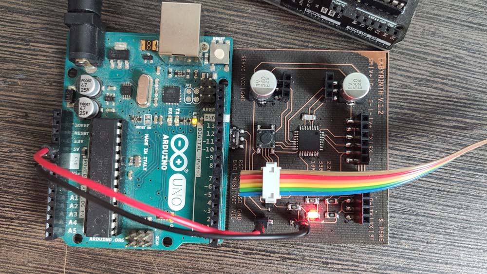
As before, I use the Arduino IDE to program the board, I compiled the Blynk example program and it blinks fine.
I uploaded a code to turn the servos to different angles, I used this labyrinth which was the first iteration of an old project. I made this using Illustrator, here are the Ilustrator and PDF files for this labyrinth.
And here is the super simple code I wrote to control these servo motors :