☐ 1. Measure something: add a sensor to a microcontroller board that you have designed and read it
☐ 2. Probe an input device's analog levels and digital signals
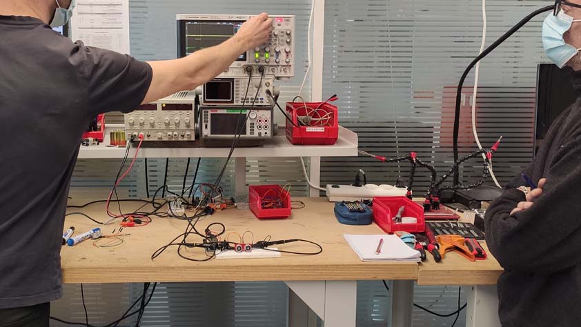
☛ Group Assignment
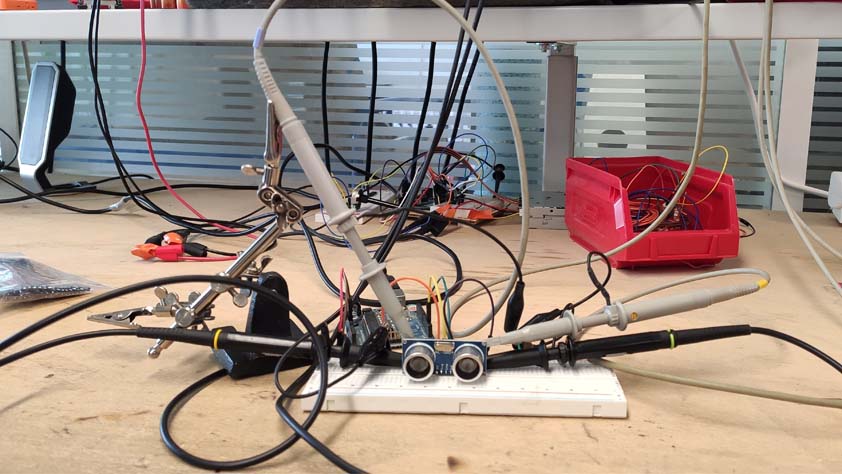
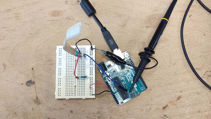
As a group assignment we took an afternoon to analyze an input sensors using the oscilloscope.
▸ Distance sensor
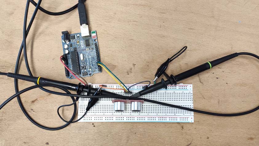
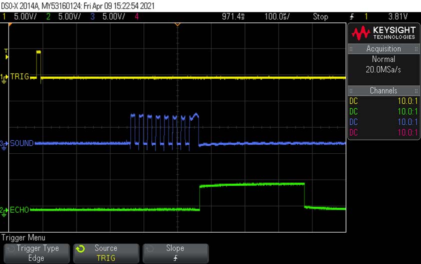
The first sensor we tried was an Ultrasonic Sensor HC SR04, a simple tutorial for using it can be found here.
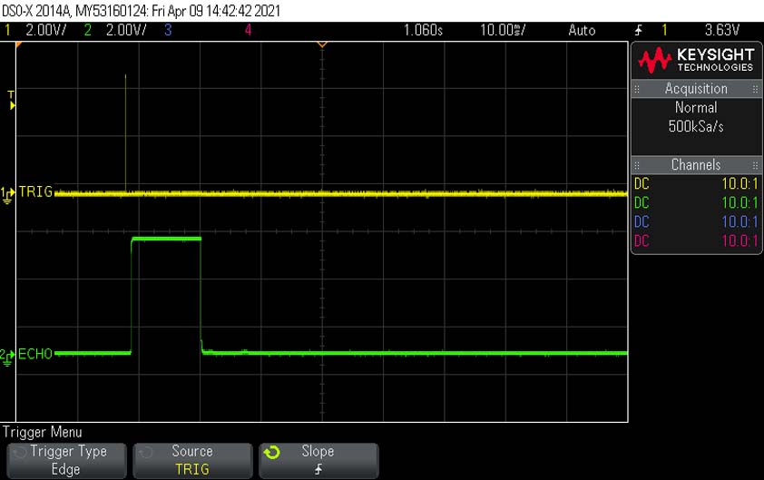
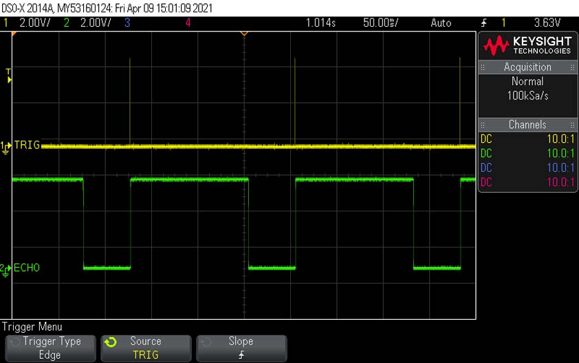
We probed the Trigger and Echo pins to watch their behavior when transmitting/receiving data, the size of the echo variation is related to the time of reflection of the signal, based on which the distance is calculated.
▸ Bend sensor
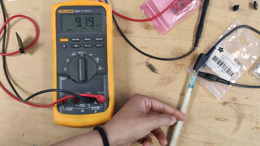
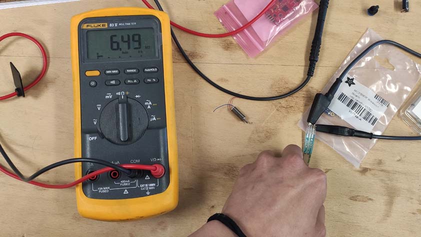
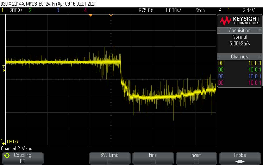
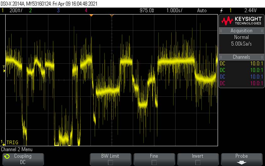
We took a look at the signal providing from the bend sensor. Its resistance is lowering as it is bended.
The first scope below show the behavior of the signal when we bend the sensor once. The second is when it is bended multiple times.
☛ Designing a board with an input to read it
This week I would like to design the board for the controller of my final project. I need to input a motor, four buttons or a joystick, a on/off switch and 4 LEDs for feedback signals. As I am using the Attiny44 so far I need more I/O pins to use all of these. Plus, I will need more pins to add a wireless module later.
/*
Shift Register Example
for 74HC595 shift register
This sketch turns reads serial input and uses it to set the pins
of a 74HC595 shift register.
Hardware:
* 74HC595 shift register attached to pins 8, 12, and 11 of the Arduino,
as detailed below.
* LEDs attached to each of the outputs of the shift register.
Created 22 May 2009
Created 23 Mar 2010
by Tom Igoe
*/
//Pin connected to latch pin (ST_CP) of 74HC595
const int latchPin = 8;
//Pin connected to clock pin (SH_CP) of 74HC595
const int clockPin = 12;
////Pin connected to Data in (DS) of 74HC595
const int dataPin = 11;
void setup() {
//set pins to output because they are addressed in the main loop
pinMode(latchPin, OUTPUT);
pinMode(dataPin, OUTPUT);
pinMode(clockPin, OUTPUT);
Serial.begin(9600);
Serial.println("reset");
}
void loop() {
if (Serial.available() > 0) {
// ASCII '0' through '9' characters are
// represented by the values 48 through 57.
// so if the user types a number from 0 through 9 in ASCII,
// you can subtract 48 to get the actual value:
int bitToSet = Serial.read() - 48;
// write to the shift register with the correct bit set high:
registerWrite(bitToSet, HIGH);
}
}
// This method sends bits to the shift register:
void registerWrite(int whichPin, int whichState) {
// the bits you want to send
byte bitsToSend = 0;
// turn off the output so the pins don't light up
// while you're shifting bits:
digitalWrite(latchPin, LOW);
// turn on the next highest bit in bitsToSend:
bitWrite(bitsToSend, whichPin, whichState);
// shift the bits out:
shiftOut(dataPin, clockPin, MSBFIRST, bitsToSend);
// turn on the output so the LEDs can light up:
digitalWrite(latchPin, HIGH);
}
Here is a video of the counting program :
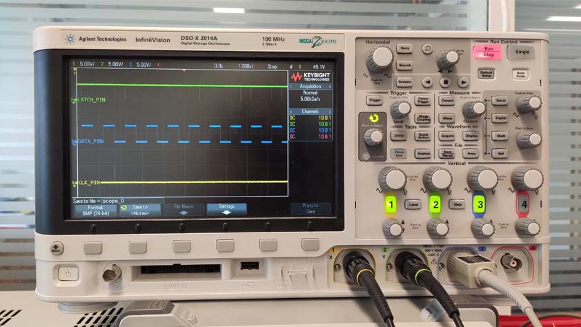
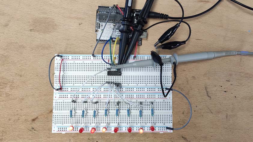
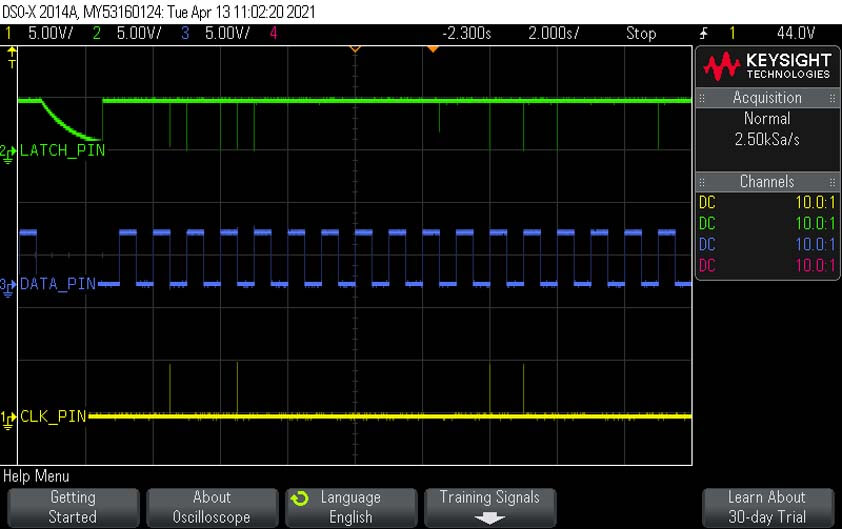
I plugged the circuit to watch the Data pin, the clock pin and the latch pin behaviors on the oscilloscope :
☛ Making a board with an Atmega328p (wip)
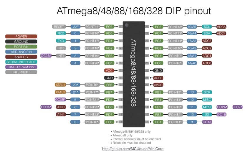
After discussing with Jonah I was advised to use an Atmega 328p microcontroller, which has more I/O pins and therefore it makes it easier to begin. I decided to draw a sketch for my circuit on fritzing before making it.
My best friend for this task, the 328 chip pinout diagram :
▸ Prototyping the BlowController circuit with switch buttons
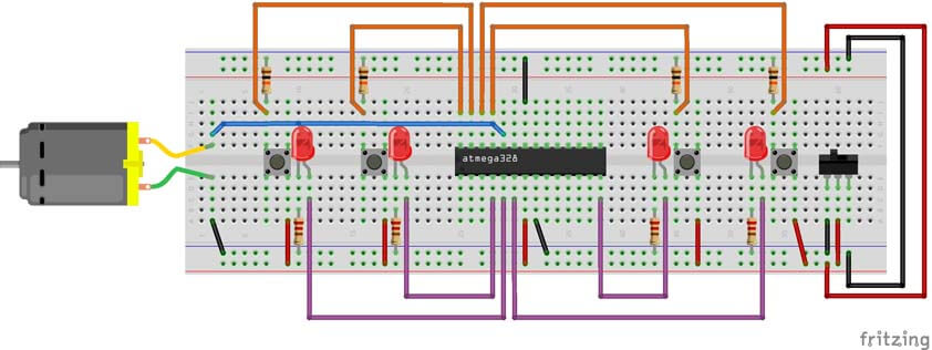
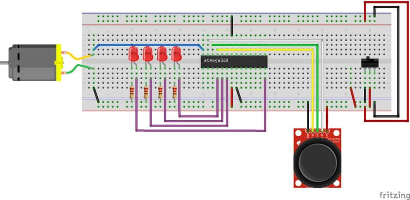
Here I want to program the Blow Controller for my final project. This controller has to be able to take the blow as an input, and to control at least four outputs, when the blow is reaching a predefined level. The following circuit should be able to do that. I use LEDs as a feedback when the button right next to it is pressed and the blow level is reached.
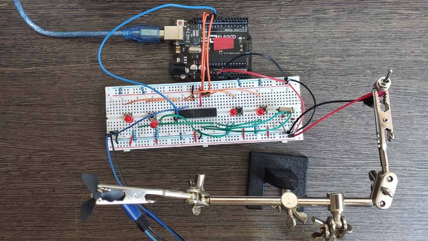
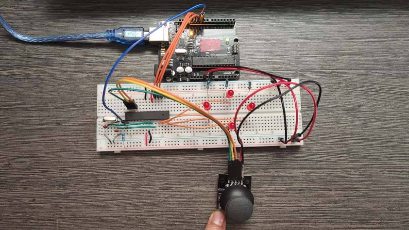
Here is the controller connected to an arduino to simulate its operations :
As it was working fine on the Arduino, I reproduced the circuit using the ATmega328 chip instead of the Arduino. The arduino visible on the video below was used to program the (braed)board.
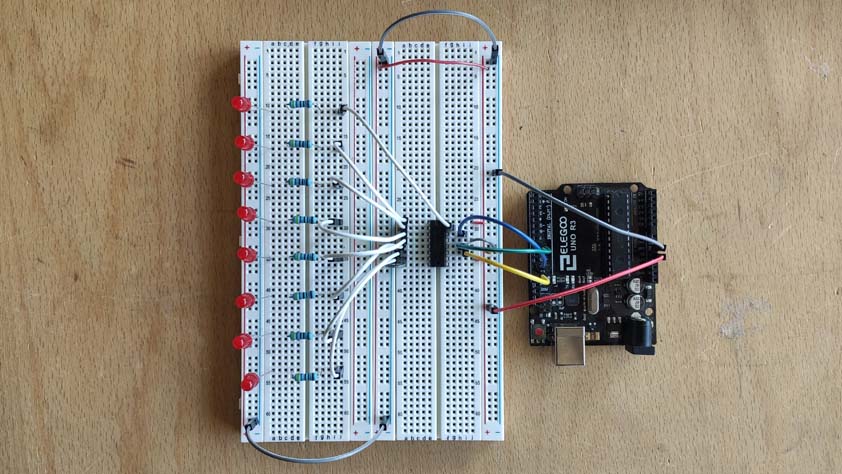
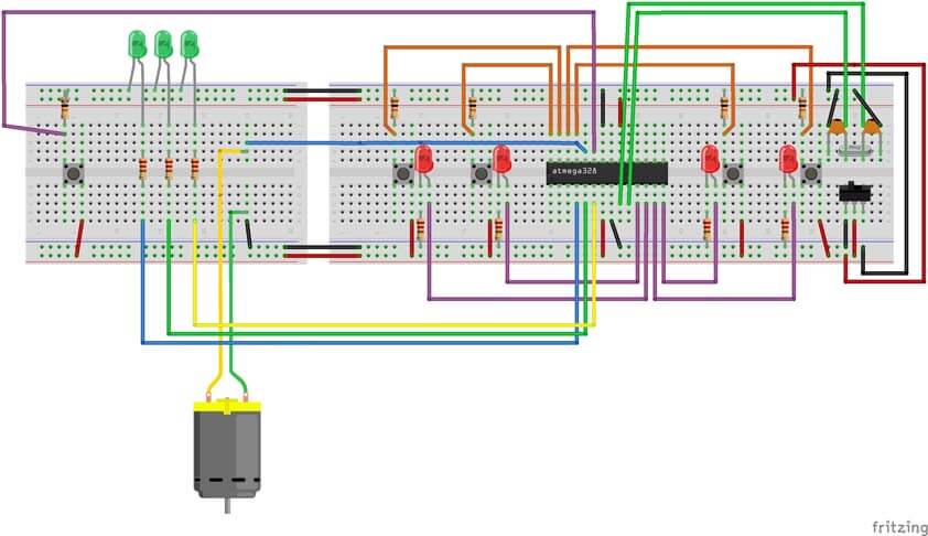
As it was working as expected, I added another function to the controller, the ability to visualize the level of blow received as an input. On the circuit below, the left breadboard is a "bargraph" activated when the switch button next to it is pressed.
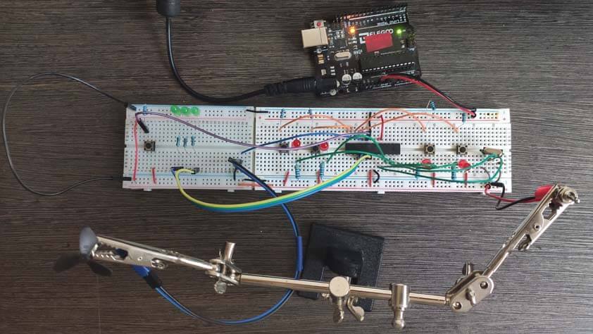
Here is the circuit on a breadboard :
The following video shows how the "bargraph" behaves. I need to find a way to "calibrate" the blow input, using a potentiometer, or an Op-amp which could amplify the signal received.
Here is the final code for this controller I manage to structure, the AnalogReadSerial Arduino sketch example helped for starting, then I am glad I spent so much time on it to make it work ! (I even created functions to make it more readable, Ok it is not much, but I feel like it is at my level.)
/*
Blow Controller using buttons
Created 24 Apr 2021
by Selena Pere
*/
int pinButton1 = A5;
int pinButton2 = A2;
int pinButton3 = A3;
int pinButton4 = A4;
int LED1 = 8;
int LED2 = 7;
int LED3 = 5;
int LED4 = 6;
int blowSensor = A1;
int barLED1 = 2;
int barLED2 = 3;
int barLED3 = 4;
int barButton = A0;
void setup()
{
Serial.begin(9600);
pinMode(pinButton1, INPUT_PULLUP);
pinMode(pinButton2, INPUT_PULLUP);
pinMode(pinButton3, INPUT_PULLUP);
pinMode(pinButton4, INPUT_PULLUP);
pinMode(barButton, INPUT_PULLUP);
pinMode(barLED1, OUTPUT);
pinMode(barLED2, OUTPUT);
pinMode(barLED3, OUTPUT);
pinMode(LED2, OUTPUT);
pinMode(LED3, OUTPUT);
pinMode(LED4, OUTPUT);
pinMode(LED1, OUTPUT);
pinMode(blowSensor, INPUT);
//Beginning LED "animation"
Serial.println("controller ON");
digitalWrite(LED1, HIGH);
digitalWrite(LED2, HIGH);
digitalWrite(LED3, HIGH);
digitalWrite(LED4, HIGH);
delay(300);
digitalWrite(LED2, LOW);
delay(300);
digitalWrite(LED3, LOW);
delay(300);
digitalWrite(LED4, LOW);
delay(300);
digitalWrite(LED1, LOW);
delay(300);
digitalWrite(LED1, HIGH);
delay(300);
digitalWrite(LED4, HIGH);
delay(300);
digitalWrite(LED3, HIGH);
delay(300);
digitalWrite(LED2, HIGH);
delay(300);
}
void loop()
{
// read the input of blowSensor pin A1:
int blowValue = analogRead(A1);
Serial.println(blowValue);
delay(1);
//Display Bargraph
int barButtonState = digitalRead(barButton);
if (barButtonState == HIGH){
barGraph();
}
//LED lit when blowed on rc motor
if(blowValue > 50){
buttonLitLed();
}
else {
turnLedOff();
delay(10);
}
}
void barGraph()
{
// read the input of blowSensor pin A1:
int blowValue = analogRead(A1);
Serial.println(blowValue);
delay(1);
if(blowValue < 50){
digitalWrite(barLED1, LOW);
digitalWrite(barLED2, LOW);
digitalWrite(barLED3, LOW);
}
else if(blowValue >= 50 && blowValue < 100){
digitalWrite(barLED1, HIGH);
digitalWrite(barLED2, LOW);
digitalWrite(barLED3, LOW);
}
else if(blowValue >= 100 && blowValue < 200){
digitalWrite(barLED1, HIGH);
digitalWrite(barLED2, HIGH);
digitalWrite(barLED3, LOW);
}
else if(blowValue >= 200 && blowValue < 1023){
digitalWrite(barLED1, HIGH);
digitalWrite(barLED2, HIGH);
digitalWrite(barLED3, HIGH);
}
delay(500);
digitalWrite(barLED1, LOW);
digitalWrite(barLED2, LOW);
digitalWrite(barLED3, LOW);
}
void buttonLitLed()
{
// read the buttons value
int button1State = digitalRead(A5);
int button2State = digitalRead(A2);
int button3State = digitalRead(A3);
int button4State = digitalRead(A4);
Serial.println(button1State);
Serial.println(button2State);
Serial.println(button3State);
Serial.println(button4State);
if (button1State == LOW){
digitalWrite(LED2, LOW);
}
else {
digitalWrite(LED2, HIGH);
Serial.println('UP');
}
if (button2State == LOW){
digitalWrite(LED1, LOW);
}
else {
digitalWrite(LED1, HIGH);
Serial.println('DOWN');
}
if (button3State == LOW){
digitalWrite(LED4, LOW);
}
else {
digitalWrite(LED4, HIGH);
Serial.println('RIGHT');
}
if (button4State == LOW){
digitalWrite(LED3, LOW);
}
else {
digitalWrite(LED3, HIGH);
Serial.println('LEFT');
}
}
void turnLedOff()
{
digitalWrite(LED1, LOW);
digitalWrite(LED2, LOW);
digitalWrite(LED3, LOW);
digitalWrite(LED4, LOW);
}
▸ Prototyping the BlowController circuit with a joystick
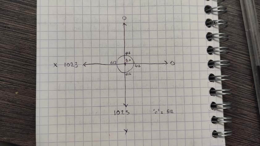
Programming is still new to me, and I think there is a solution that is lighter to make the same thing. The sketch below shows the joystick axis and their values, I defined a "mid zone" and used the values out of it to specify when a direction is taken. (ok, sentence to clarify).
Here is the result for this :
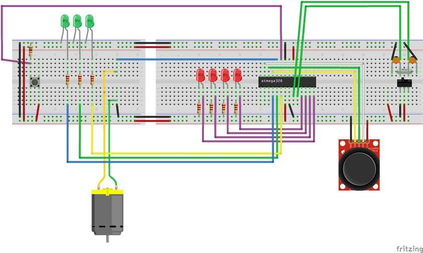
Next, I added the bargraph to this controller as well.
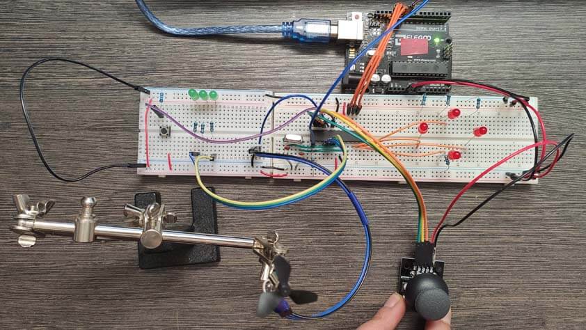
Here is the circuit of the Blow Controller with a joystick on a breadboard.
And here it is working :
Here is the final code for this second controller, the tutorial linked helped me to understand how to control the joystick, and here again I am glad of what I achieved in programming :
So far, I wasn't able to read the serial communication from the board. I think I don't have the right FTDI cable. Update to come.
☛ Making the PCB for the Blow Controller
This is the update, published on june 1st.
▸ First attempt
I used the circuits I made on breadboards to translate these big circuits in a condensed one. I designed the PCB using Eagle, the process I used is described in Electronics production.
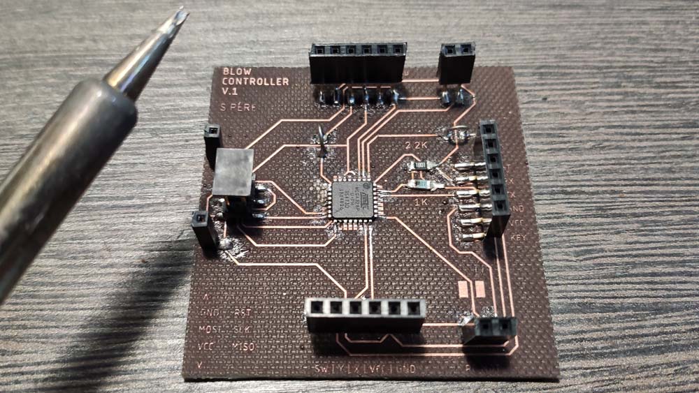
This first attempt has several issues : the text didn't came out well as the size is too tiny for the letters to survive this process, I will modify the text size to 0.5 instead of 0.4.
Antoher issue I met was soldering itself. My soldering iron has big tips, and therefore it was complicated to soder the microcontroller. In this attempt I only soldered the pins that are being used in the circuit. A bigger issue this board has is missing components, after showing it to my insructor, I forgot the reset resistor that is required. Also, a capacitor for the microcontroller and a polarity protection would be better to add.
▸ Lasercutting & Soldering
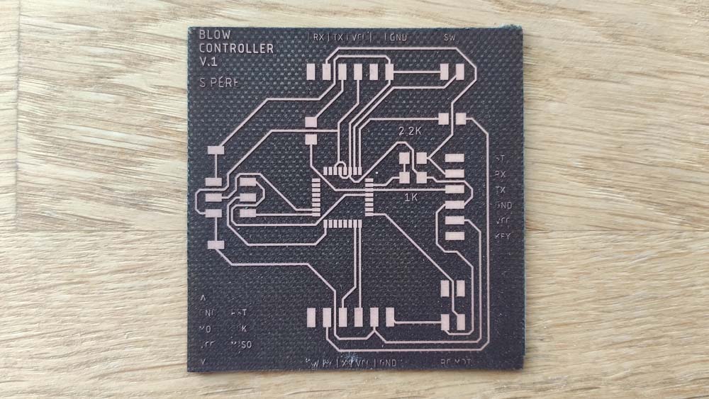
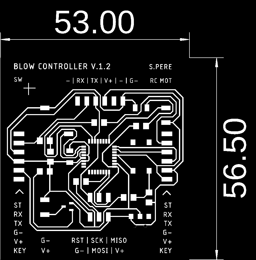
Using the advices Jonah provided me, I modified the board and added the components that were missing.
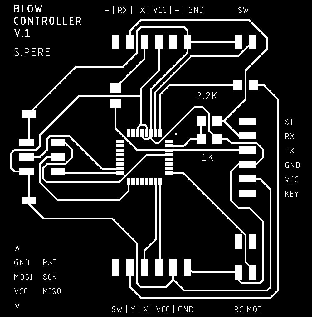
Here is the final circuit schematics for the Blow Controller, the image can be enlarged in another window.
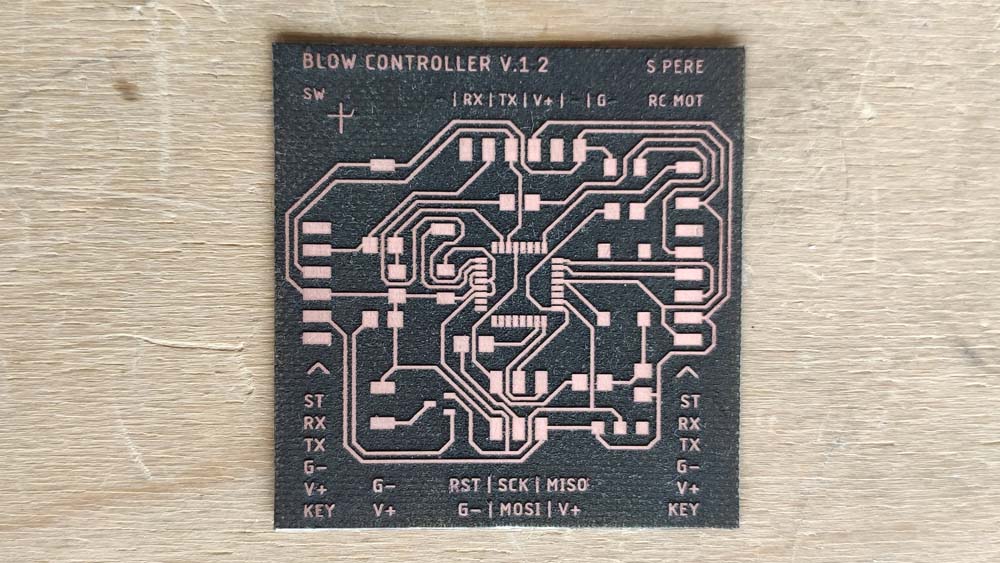
This time, using a heavier size for the font, the text came out very well.
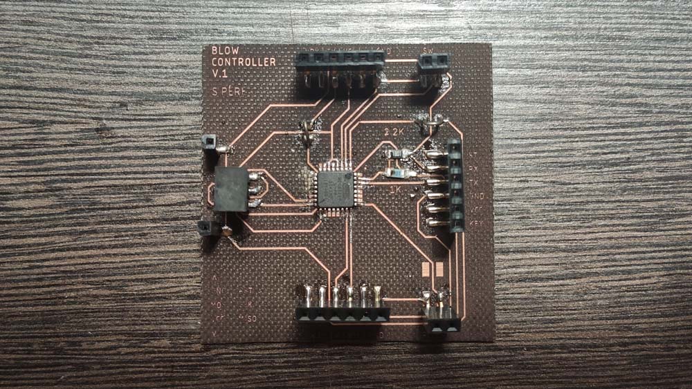
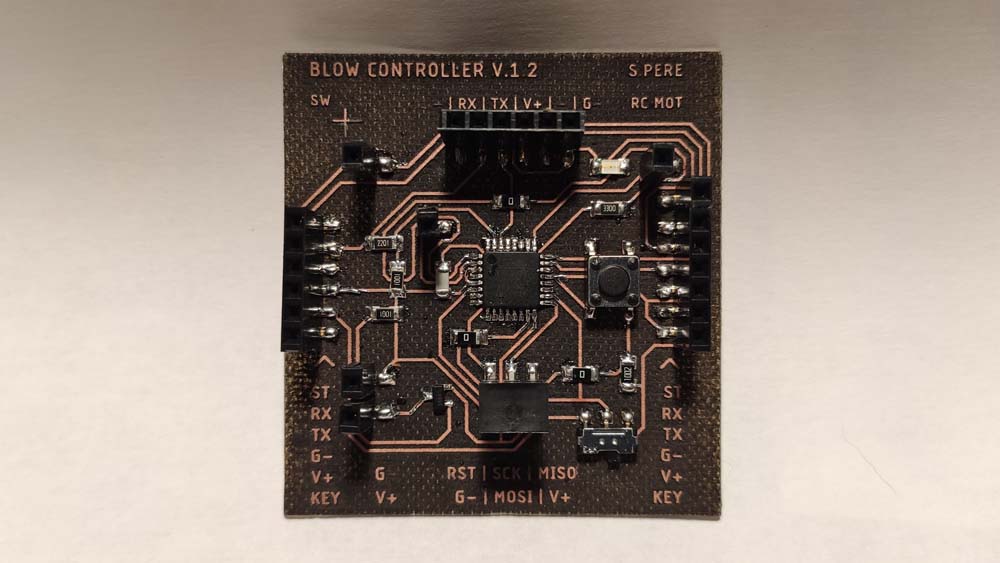
The soldering part was also easier by using a soldering iron from the fablab, their tips are thiner, the microcontroller was a little bit easier to solder.
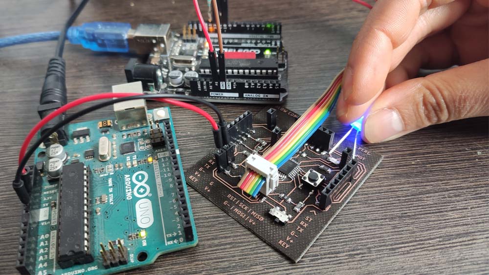
▸ Programming and testing
I used the Arduino IDE to program the board using an Arduino as an ISP and another Arduino to power the Blow Controller board. I uploaded the Blynk example in it and it works, but the LED isn't working. I will have to desoldered it to solder another one.
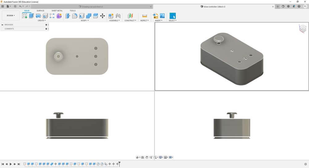
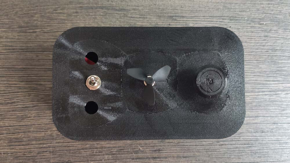
I designed this box in which I will integrate the board. It is alo a useful print to test the ergomy and proportions of the controller.
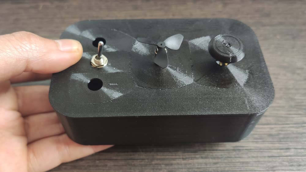
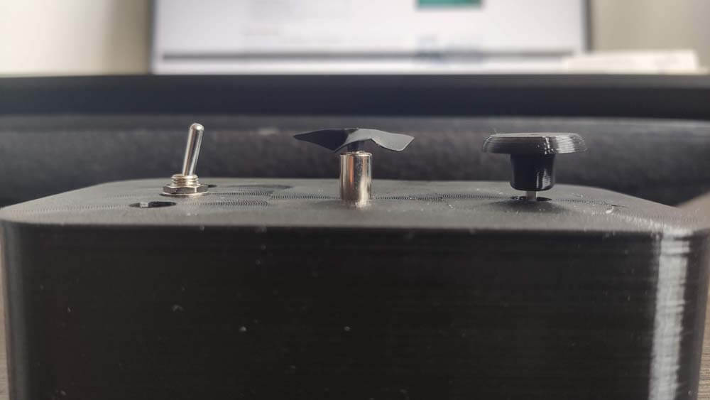
After a few hours printing :
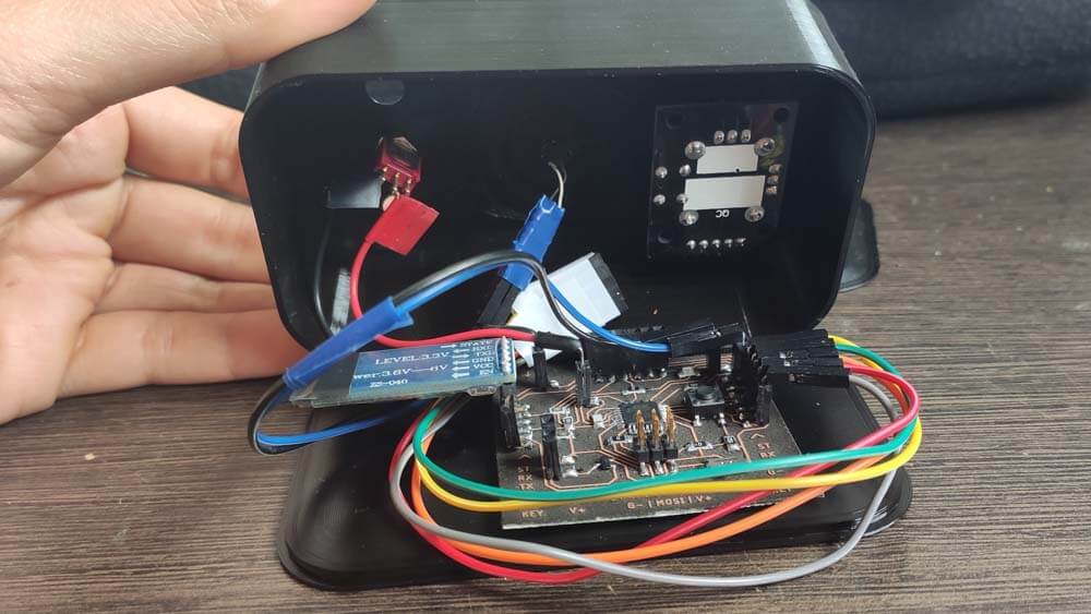
I still need to make some soldering and tidying in the wiring. Also, it needs a few modifications to add the bargraph and another switch.