Week 5 : 3D Scanning & Printing
☛ Group Assignment
☐ 1. Test the design rules for your 3D printer(s)
☛ Individual Assignment
☐ 2. Design and 3D print an object (small, few cm3, limited by printer time) that could not be made subtractively
☐ 3. 3D scan an object (and optionally print it)
☛ Testing the design rules of our 3D Printers
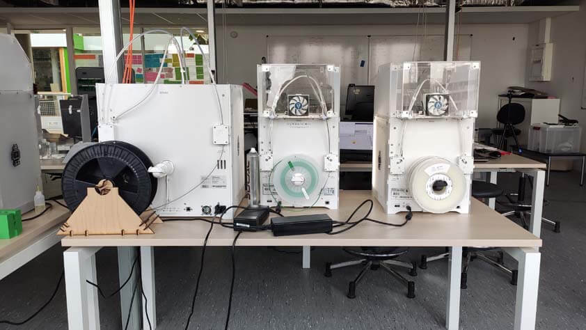
This week we are discovering and testing the 3D printers at the Fablab Digiscope, several models from Ultimaker.
☛ Ultimaker 3, Ultimaker 3 Extended, Ultimaker S5
At the beginning of the week only 2 of the 5 Ultimakers installed in the lab were working properly, mainly because there is less users at the moment. As we are now more users for those machines we decided to begin by cleaning the machines before using it : the print cores, the built plates, inside the box itself. This was a very useful first encounter it permitted us to understand how it works.
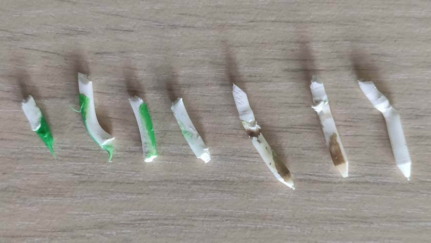
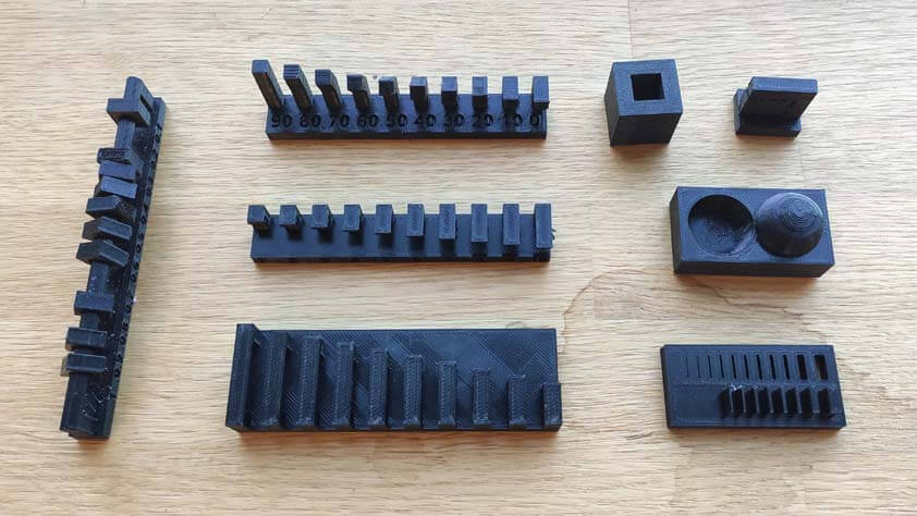
We easily found tutorials to go through these steps. This one, the Hot and Cold Pull is the process to clean the print cores. We didn't have Cleaning filament so we took white PLA Filament instead, the first four pieces of PLA in the picture below are demonstrating the Hot Pull process. It consists in inserting filamanet through the head until it resits when touching the hot print core. Then pull it of in a movement, and doing it again until the filament becomes clear. The three next pieces demonstrates the Cold Pull process, the 3D printer heats the print core, tha filament has to be inserted, but instead of pulling it off right away we have to wait for the nozzle to lose heat. When the print core is maintained at a low temperature we can pull it off. The process has to be repeated until the filament is clear.
The next step is to calibrate the built plate, so the print core can let out filament in an harmonious way. Here a several tutorials from Ultimaker to set up their 3D printers properly, the process is slightly different regarding the interface of the model, but the process is basically the same, plus in comparison with of the Ender 3, Ultimakers model are very assistive during these steps.
The last link is the error one of the printers shows, we didn't have time this week to look into it deeper, so this is a reminder.
- Inserting filament
- Levelling the Ultimaker 3 build plate
- Levelling the Ultimaker S5 build plate
- ER17
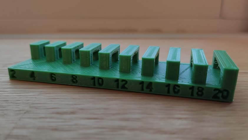
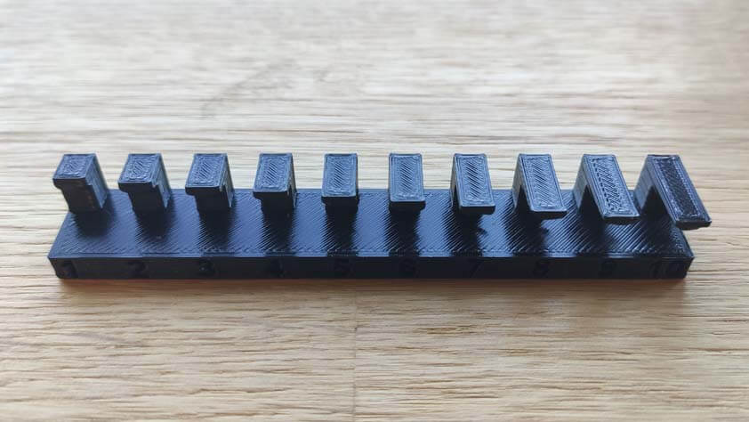
☛ Ultimaker 3 / Nozzle 0.4mm / Layer height 0.1mm
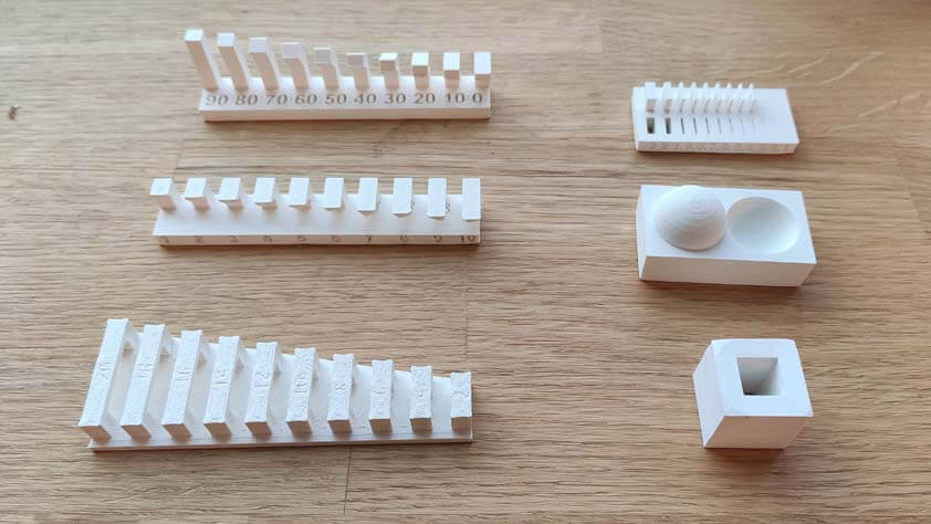
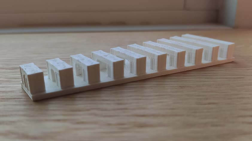
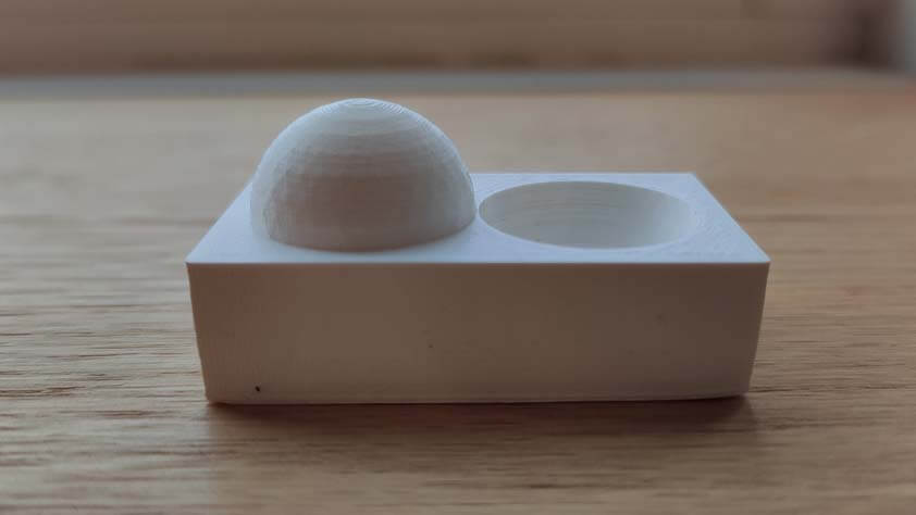
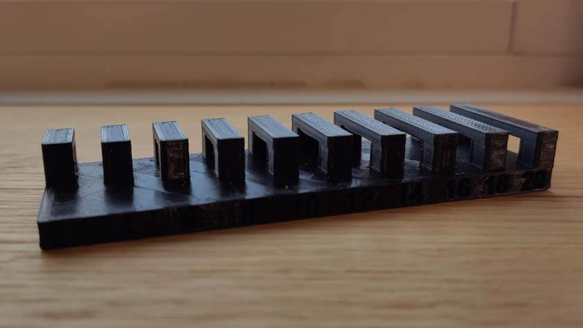
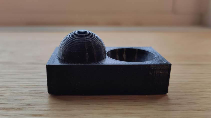
To go through his assignment we decided to use the files provided in the course page. Printing these models allowed us to discover the limits of the printers regarding their capabilities and the parameters we were using. Here is a table showing the results we obtained :
| Test | Minimum result |
|---|---|
| Angle | 30°-40° |
| Overhang | 1-2mm |
| Bridging | 14mm |
| Wall thickness | 0.4mm |
| Surface finish | Great |
| Dimension | - |
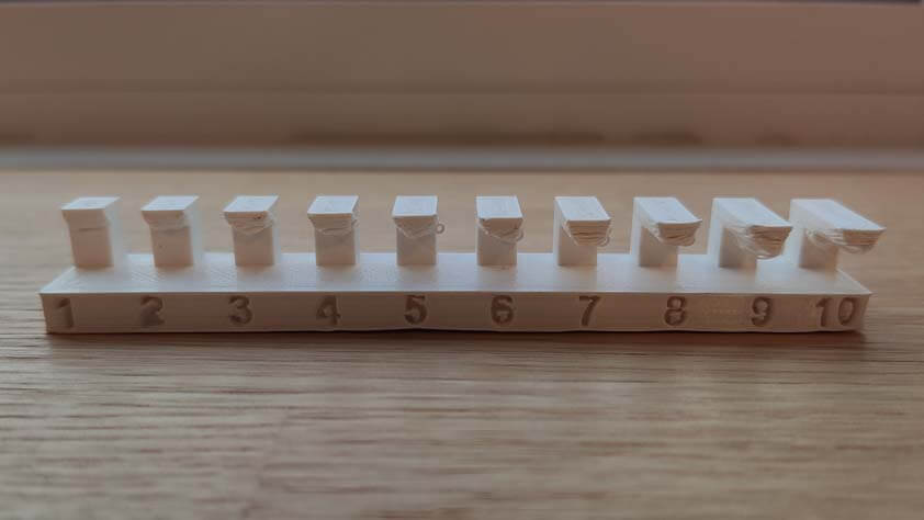
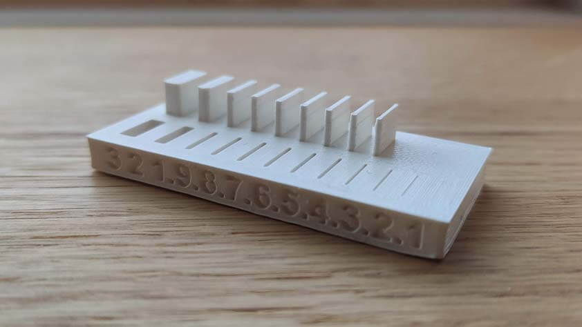
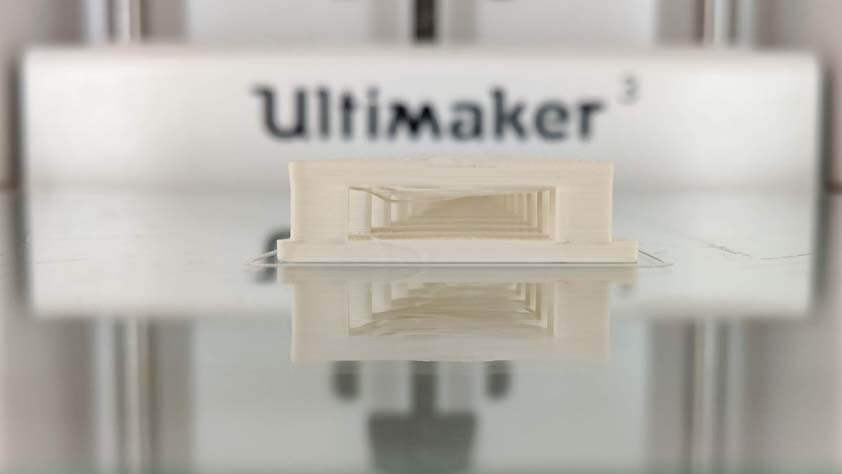
Ultimaker designers probably thought about this particular moment in the users practice, taking picture in course and at the end of the printing process. This is neat, maybe too much, but this is a satisfying display.
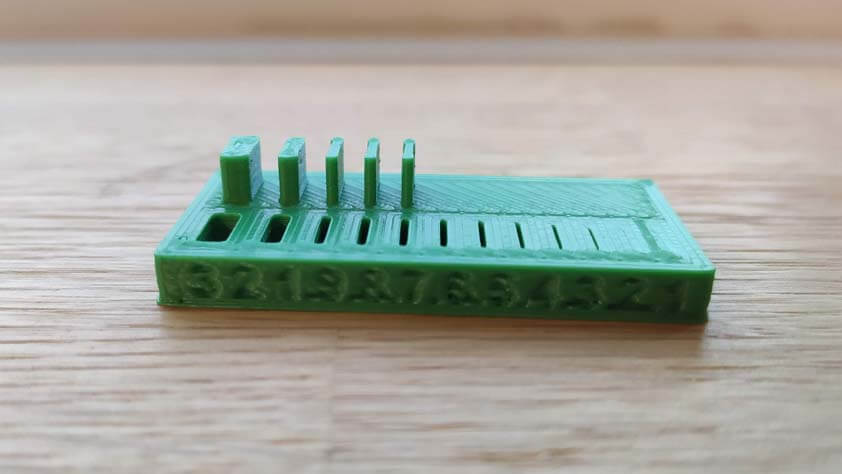
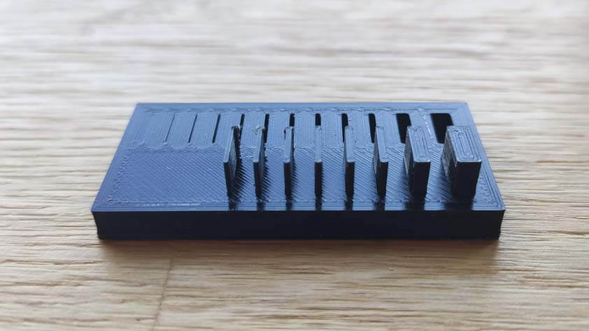
☛ Ultimaker S5 / Nozzle 0.8mm / Layer height 0.2mm
This printer was longer to put to work, it kept showing error messages like "Nozzle probe failed. Please check the nozzles and bed and try again", "Active leveling could not be performed. Please check the nozzles and bed and try again.", "Difference between detected height of both print cores exceeds realistic values.", or "I decided I will not work for the moment, but something check somewhere else and try again later."
This was frustrating because at first I checked the nozzles and bed the three first times it asked me for, so I decided to try again without checking anything, and it worked. It was a fast job, so I started it again, and nope again.
The printer became more compliant and we could 3D print the calibration tests. Here are our results :
| Test | Minimum result |
|---|---|
| Angle | 30° |
| Overhang | 2-3mm |
| Bridging | 16-18mm |
| Wall thickness | 0.8mm |
| Surface finish | Rough |
| Dimension | One side is larger thant the other .8 mm of difference |
☛ Ultimaker 3 Extended / Nozzle 0.25mm / Layer height 0.1mm
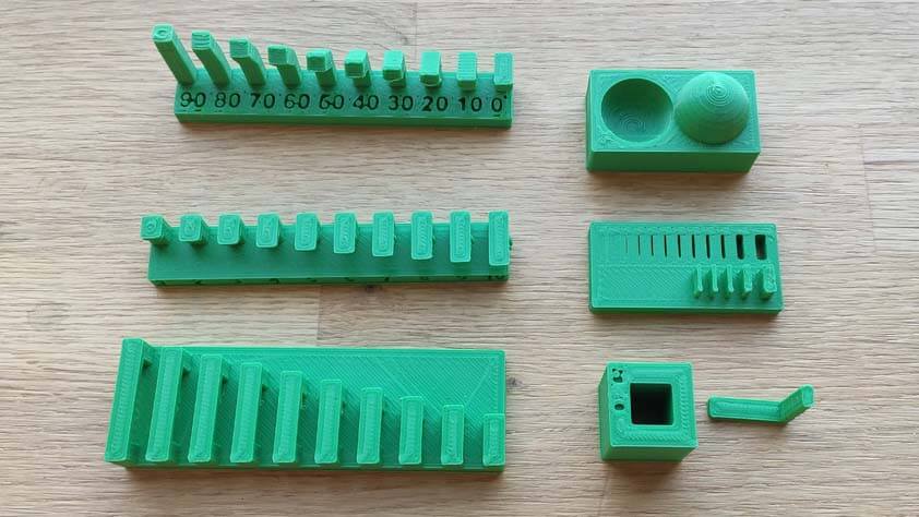
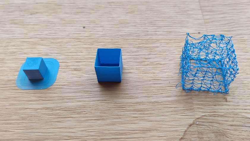
The Ultimaker 3 extended is the Ultimaker 3 but higher. We installed a 0.25mm print core, so we have 3 differents settings we can test. Here are quick experimentations on cubes using Cura Special and Experimental Modes.
- The first on the left is a 10x10mm cube with a brim.
- The second is a 15x15mm cube with "Spiralize Outer Contour" and 0.3mm "Fuzzy Skin" ticked.
- The third is a 20x20mm cube with 0.3mm "Fuzzy Skin" and "Wire Printing" ticked
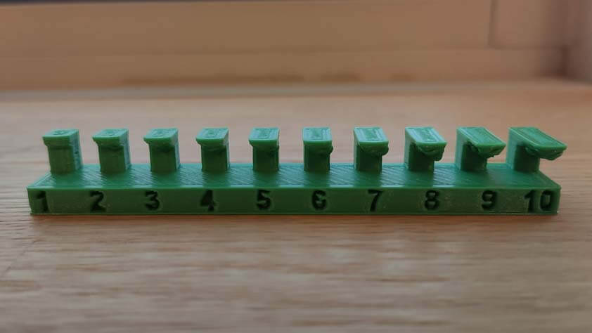
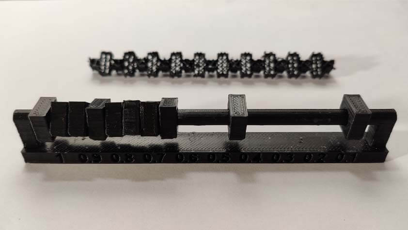
☛ Creality Ender 3 / Nozzle 0.4mm / Layer height 0.2mm
I made the acquisition of a Creality Ender 3 almost a year ago, it is 18 times cheaper than an Ultimaker 3, and so far I think that it is a more comfortable machine to use because you can make errors on it that will clearly show you what's is mechanically wrong. I found that this is limited on an Ultimaker because it doesn't let you that ability, it shows error messages before. But yes, okay, you can simply plug and unplug a new nozzle, basic tasks as the calibration travel and heating/cooling when it is time to change the filament or cleaning the print cores are mostly automated and supported by sensors. And, yes also, the Ender 3 is a very noisy machine (regarding this, upgrading to the silent motherboard V4.2.7 has been a real improvement regarding noise emitted. The noise remaining is mostly caused by the fans cooling the extruder and the nozzle.), it takes a large amount of time to calibrate the build plate the first times, and changing a nozzle is much more challenging than with an Ultimaker. Even with that, my preference goes to Creality.
I reproduce the calibration tests using the Ender 3, and the results are quite satisfying, particularly regarding the angle of printing and the bridging tests.
| Test | Minimum result |
|---|---|
| Angle | 10-20° |
| Overhang | 2mm |
| Bridging | 20mm |
| Wall thickness | 0.5mm |
| Surface finish | Cool |
| Dimension | One side is larger thant the other . mm of difference |
| Clearance | 0.2mm is tight but moves, 0.1mm is stuck |
☛ Design something that could not be made subtractively
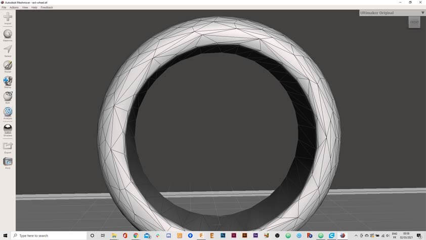
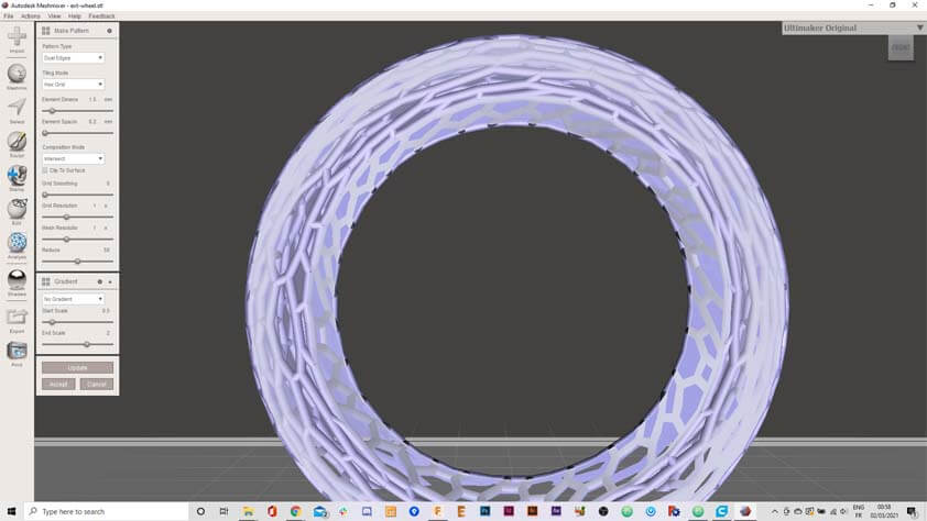
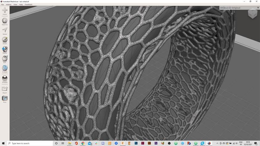
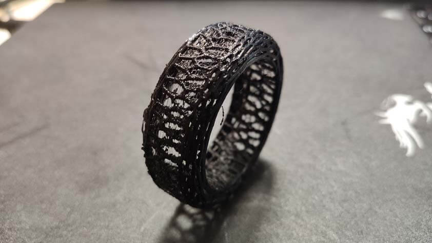
For this part I tried to make sort of airless tires for the "Drawing Car" I designed during Week 2. I exported a STL file from my previous work and imported it in MeshMixer Autodesk. Here are the steps I went through :
- Select the model and display meshes, then
- Click Edit > Reduce 50%, and repeat this step : it works better if there is less triangles
- Clear the Selection
- In the left panel, select Edit > Create Pattern
- In the window appearing select Dual Edges pattern and modify the parameters until it fits, and click Accept
- You can then export the file
Here is the 3D model of this object on Sketchfab
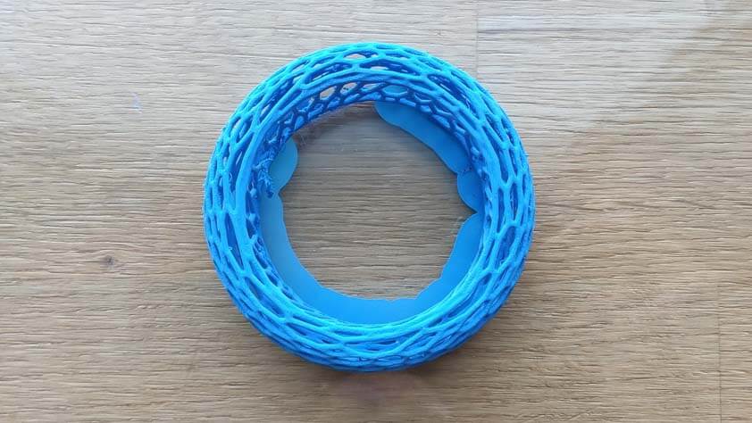
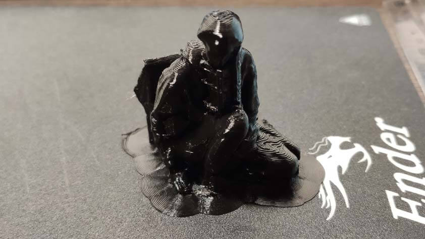
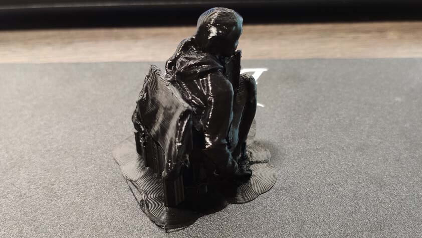
Here is the 3D printing attempt with the Ender 3. I reduce the size of the tire from 80mm of diameter to 50, so it would take less time to print. Thinking twice, this was not a good idea as the meshes were already 1mm of width. The result shows a lot of stringing on the printed model, it probably means that the retractation of the filament is too slow in that attempt.
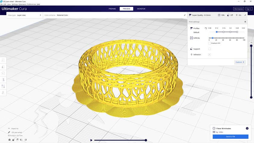
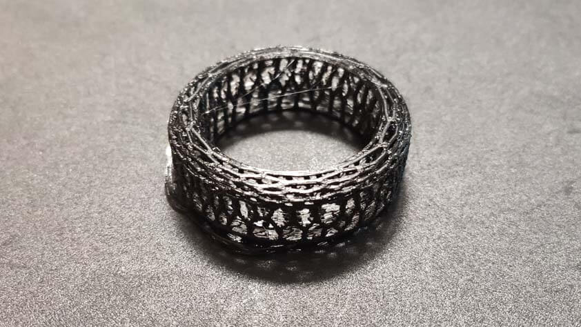
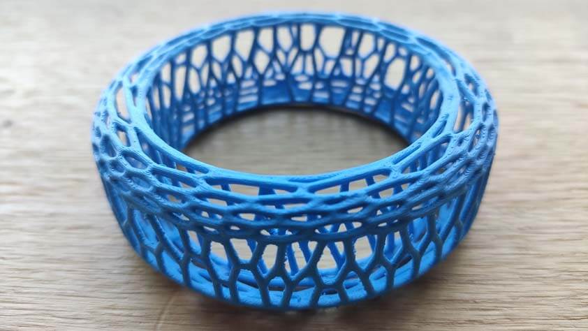
I made another try with the Ultimaker 3 Extended, using a nozzle of 0.25mm. I kept the reduced size of the model for this test as well, there is less of the stringing effect, but there is still. I had to use an adhesion support, between the model and the build plate only, because it would not adhere to it without. This is not ideal as it is hard to pull it off of the model without damaging it.
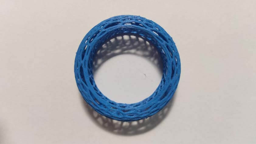
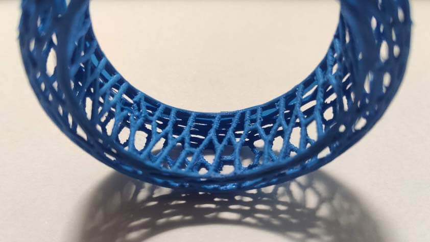
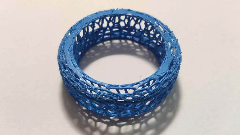
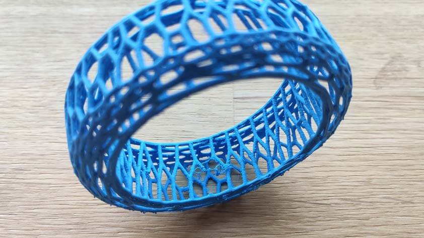
Here is another attempt, still using the Ultimaker 3 Extended, with 0.1mm of layer height, 20mm/s of travelling speed, 28mm/s of retractation speed, and "Enable retractation at layer speed" ticked, in Cura slicer. Stringing is less present but the brim is still hard to get rid of, and the bottom layers (the first layers printed) are not very smooth. At this point I could try to lower the heat of the print core, or just redraw this model so the angle is easier to produce with this machine.
☛ 3D Scanning
Sample text
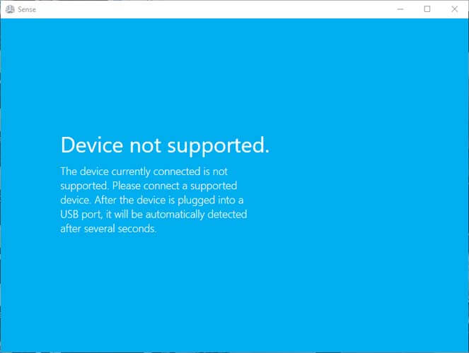
☛ 3D Scanning with the Sense (failed attempt so far)
I tried a long time to understand why it would not work, but it doesn't work, I installed both versions of the software, in case I was wrong from the beggining. I probably missed a step and it took me hours not to succeed in making it work with my computer.
3D Systems Sense v.1 Sense Scanner softwares Intel RealSense SDK 2.0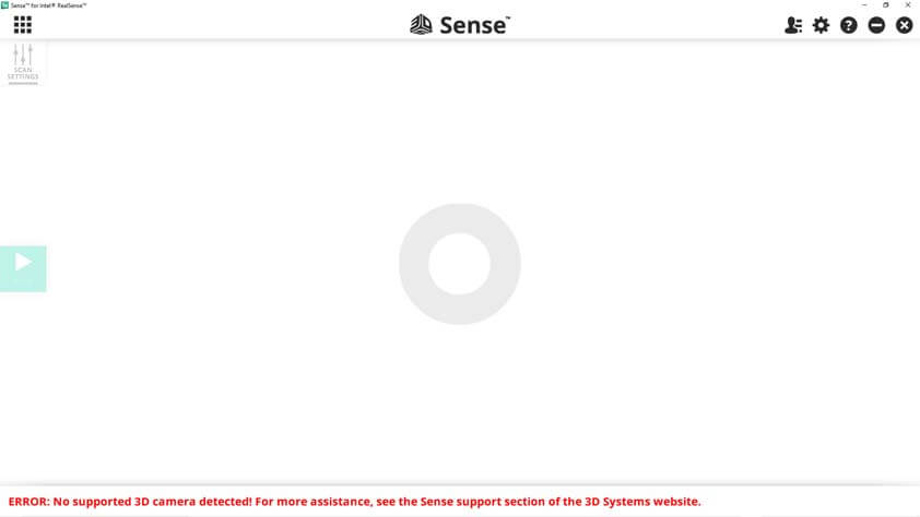
☛ 3D Scanning with a Kinect
Fortunately, we have a Kinect at the Fablab, I had issues to find a software that would work with it. I first followed a tutorial to use it with Skanect software but it did not detect the Kinect and I still don't know why. I installed Kinect Studio but it asked for a Kinect Enabled App, so I went through installing different softwares that are "Kinect Enabled", none of them worked. I tried 3D Scan, whiwh was suggested in the Microsoft app store, it detected the Kinect at first opening so I went with it.
Kinect for Windows SDK v1.8 and the Kinect for Windows Developer Toolkit v1.8
"4 Kinect enabled apps" 3D Builder 3D ScanThe process is very simple, as minimalistic as the interface. In the 3D Scan left panel it possible to
- Adjust the depth
- Adjust the width
- Adjust the height
- Rotate the Scan zone
- Add a timer
The first test I made were using my desk chair, which is the only rotative thing I could think of and find at my place. I installed the Kinect on a tripod and adjusted the parameters to scan properly.
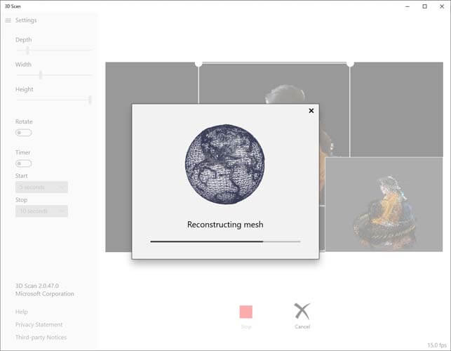
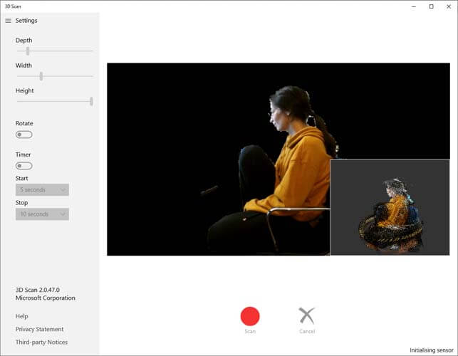
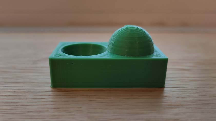
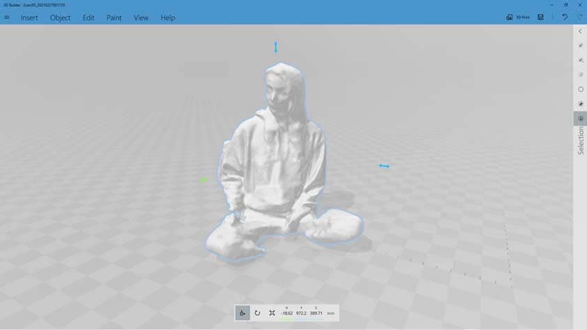
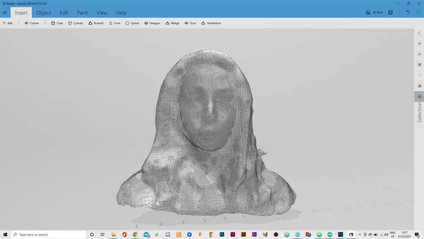
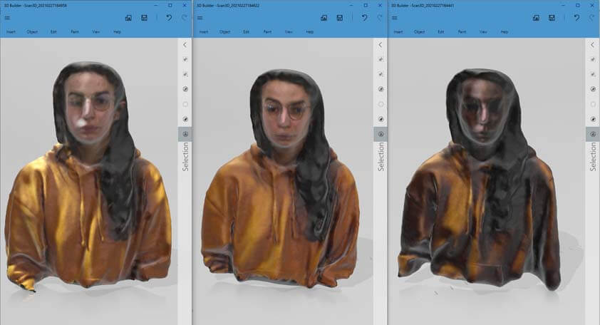
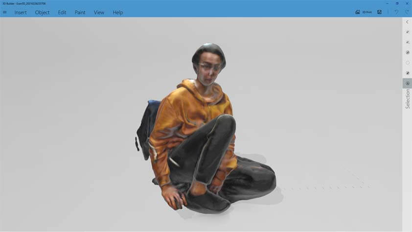
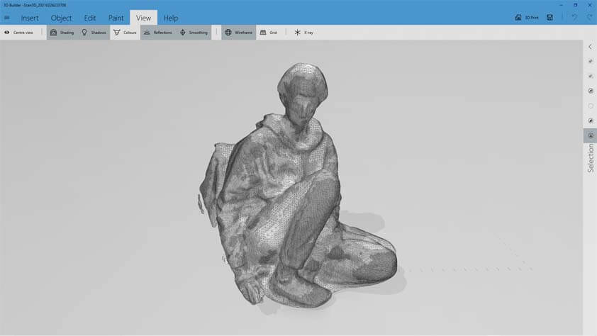
Once the scan is done, 3D scan constructs the meshes that can be open in 3D Builder. This was my first time using a 3D scanner, so the result is quite pleasant. I tried to makke a closer scan, and modified the lighting "set up" I have (lamps). There is less details when the scene is under-lighted, but too much light seems to distort the subject. (Or it could be me).
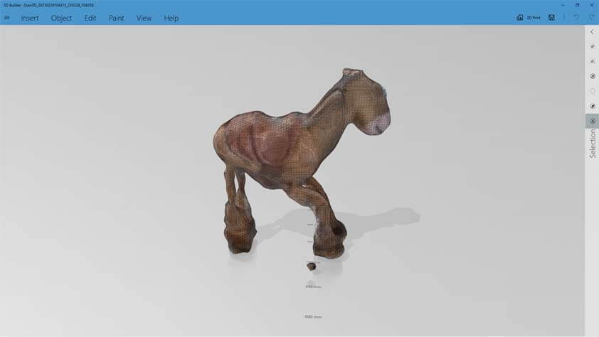
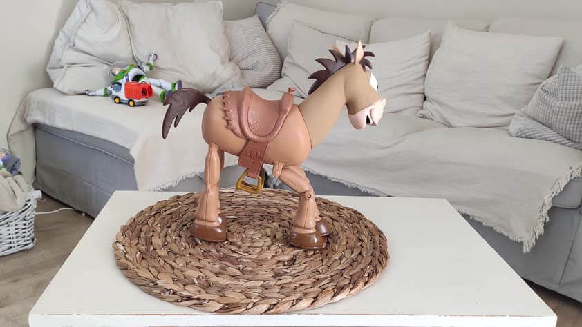
I tried to scan a toy from my nephew (I tried to scan my nephew first, but the "not moving" part was complicated to achieve). And I think the light set-up is in cause in that result, there wasn't enough light.
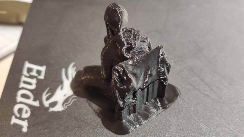
I selected the more detailed scan I had made so far and exported it top open it with Cura Slicer without any modification.
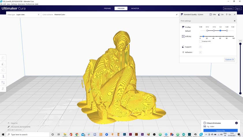
It was printed with support, as the model is not "plane", and with a brim because it would not adhere - adhesion issues on my buildplate ? After two hours and ten minutes :
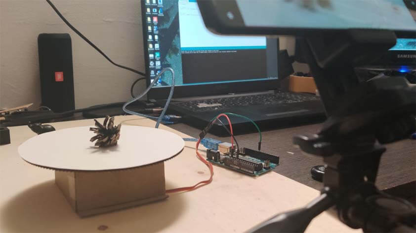
☛ Photogrammetry setup
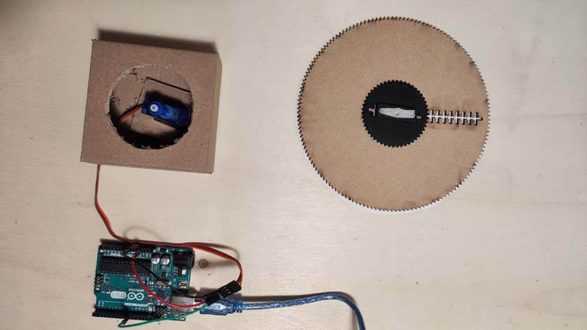
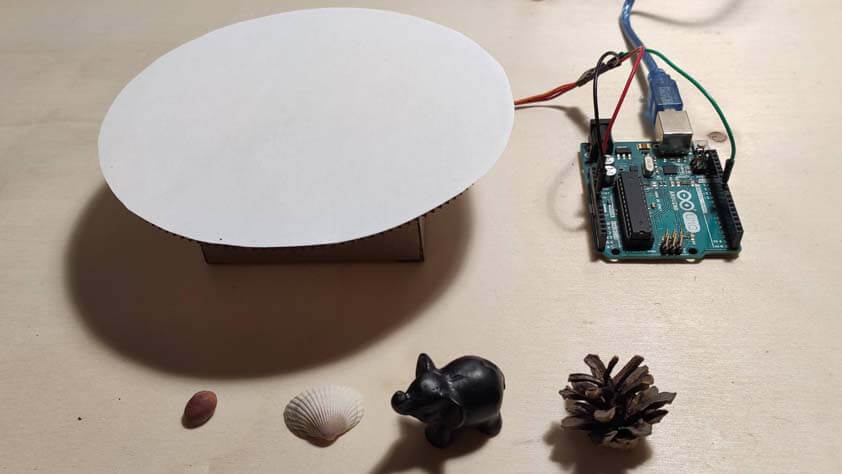
I really wanted to try photgrammetry with a turntable so I made one. I took a part of an older project, a large laser cutted gear and a continuous servo. The continuous servo was installed in a card board box, the gear was slightly modified so the servo can make it turn. Then I double taped a white piece of paper as a clear background.
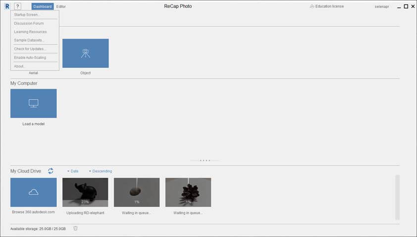
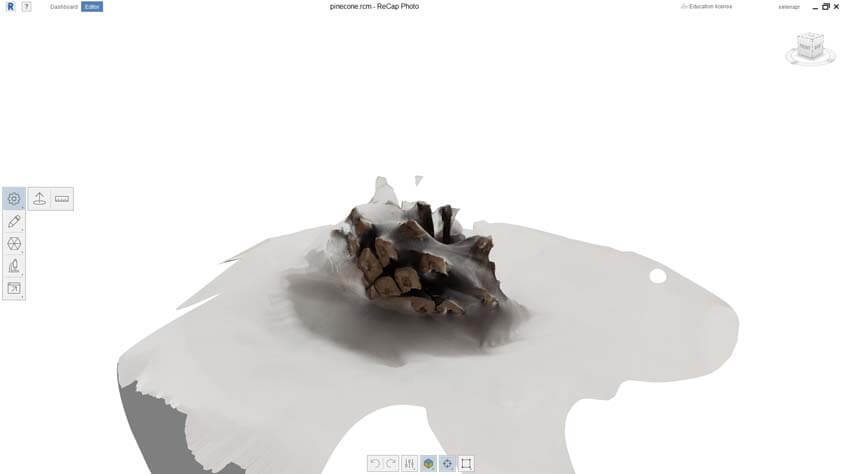
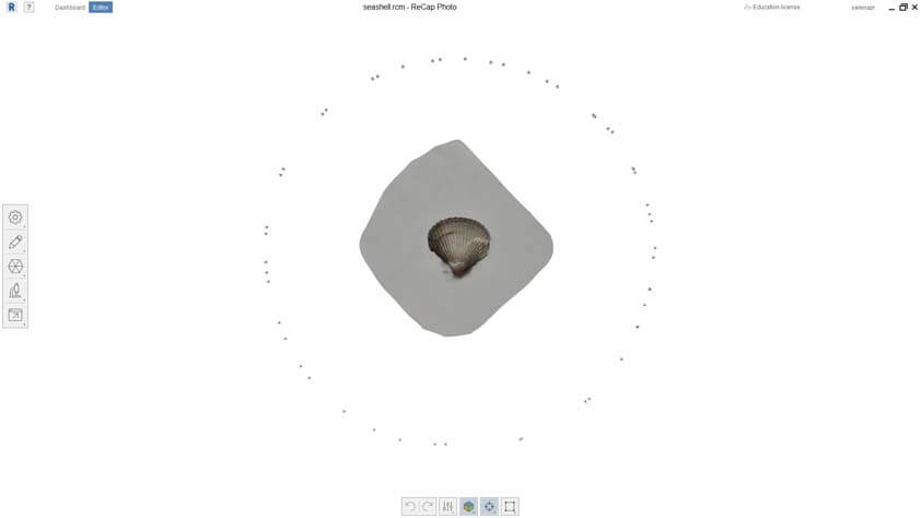
☛ 3D Scanning using ReCap from Autodesk
Recap Photo is an Autodesk scanning software.
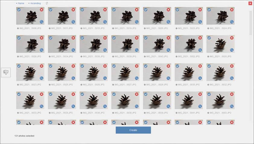
Once I had took all the pictures I needed, I tried to import them in ReCap. The amount of images you can import is limited, 100 is the maximum pictures you can process at a time.
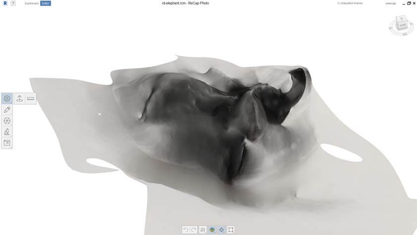
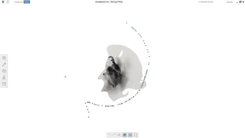
Here are three reconstructed mesh from my pictures. The first image is a little black elephant, but as you can see on the picture below it, the cameras are not placed all around the scene. But it was a dark and reflective material.
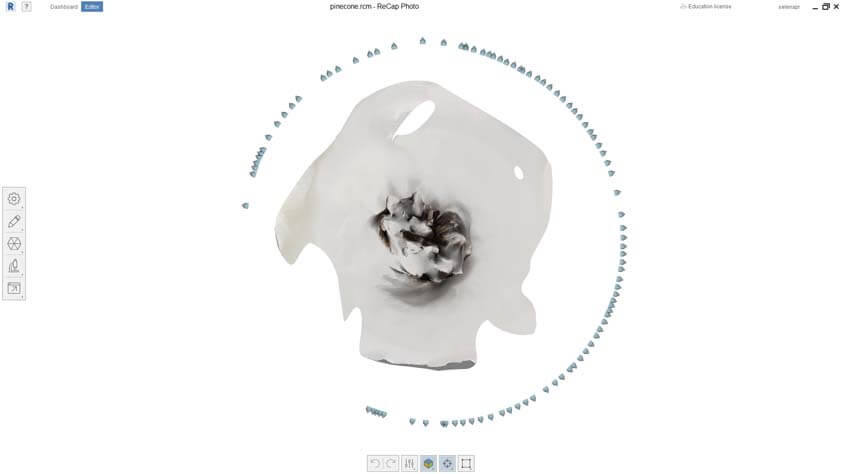
the second image shows the reconstruction attempt of a little pinecone I brought from Lahti in Finland (very important detail), as it is a complex shapethe result is not totally surprising, plus the cameras aren't tracking efficiently again.
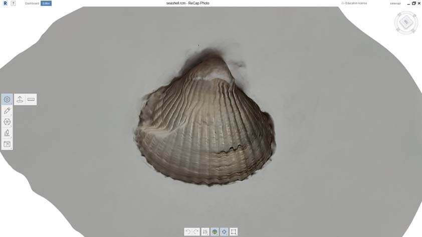
The last one is a seashell, as it is a simple shape with a poor reflective capability, the result is more accurate, there is still an issue regarding tracking.
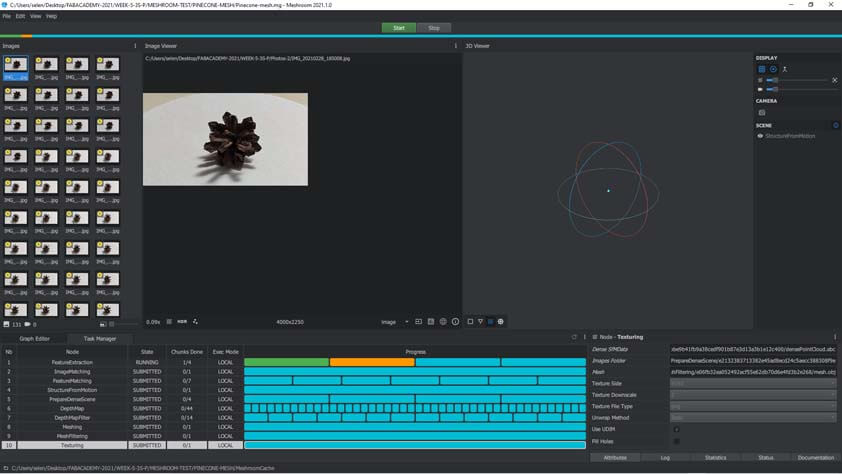
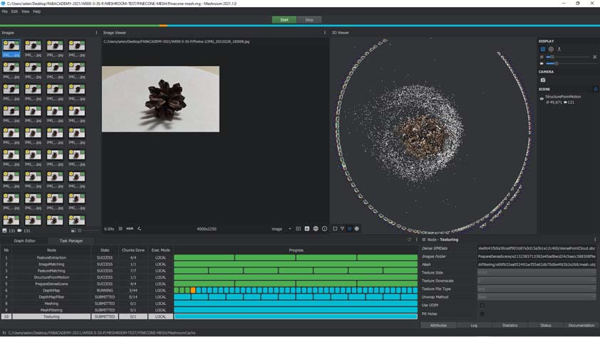
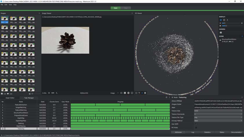
☛ 3D Scanning using MeshRoom
The link to Meshroom
I tried to import my pictures in MeshRoom.
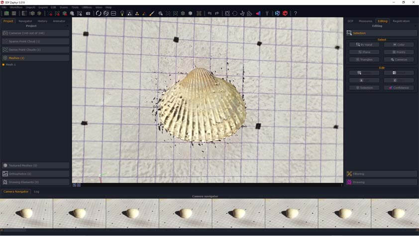
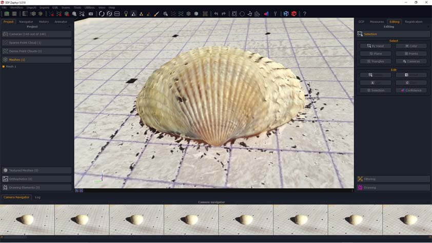
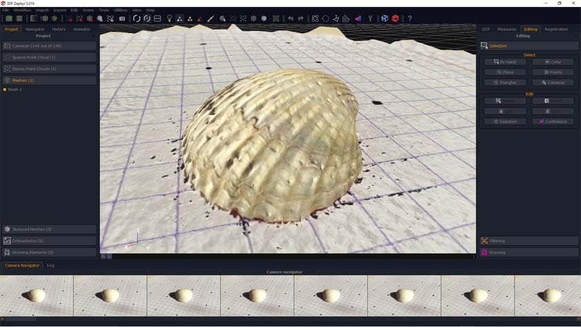
☛ 3D Scanning using 3DF Zephyr
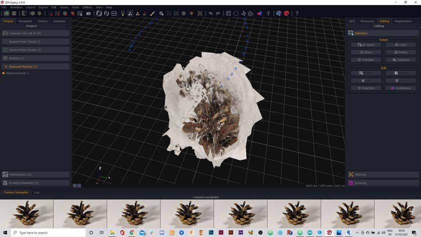
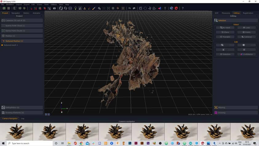
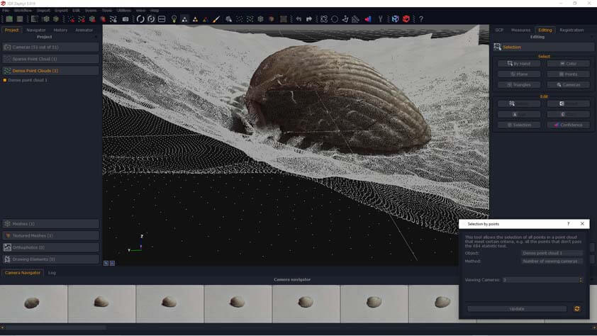
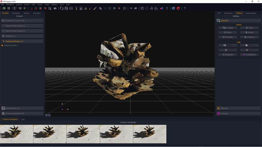
3DF Zephyr I downloaded 3DF Zephyr with the 14 days free trial license. I imported my pictures in it. I found the interface easier to understand than MeshRoom, and it is possible to edit the mesh after the reconstruction. This first row of images shows the reconstruction attempt of the pinecone, but the tracking is a real issue that I missed so far so I cannot do anything with that result.
I tried again with the seashell, the editing features allowed me to select a colour range an delete it. But I couldn't export a model anymore after this. This issue could probably be resolved with more time.
☛ Photogrammetry setup update
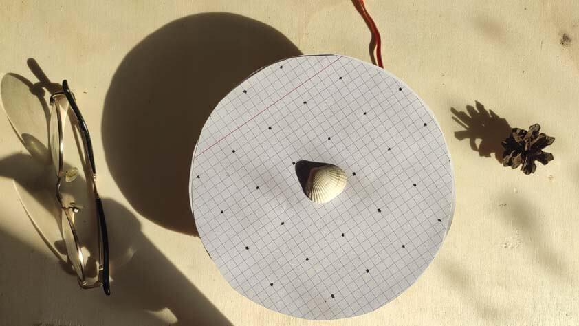
After realising several test it occured that the fact that I was using clear white paper was making it difficult for the software to track the object, so the result would not be useful as a scanned object. I took a grided paper and added dots on it. Ambroise told me that the result would be more efficient if the grided pattern is not regular, a page of newspaper would be better because with all the block of text of different sizes the sofwtare can differentiate where it is around the objets more easiy.
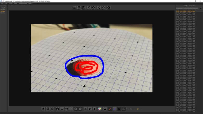
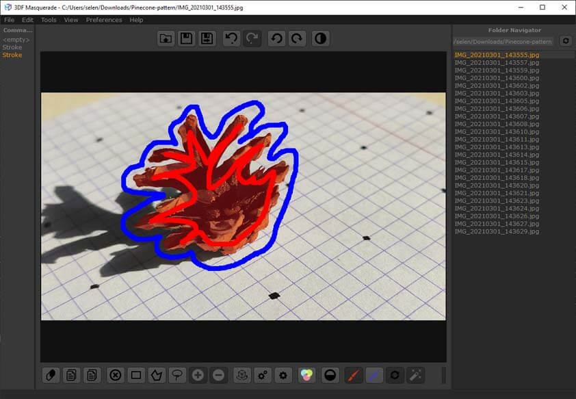
A tutorial for using the masking tool on 3DF Zephyr and another tutorial to do it with a turntable
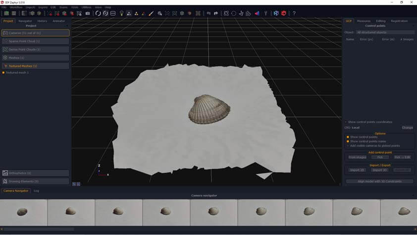
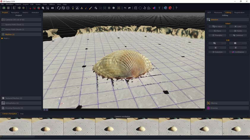
I added my grided background and the result was better, but the grided background is reconstructed as well. Ambroise advised me to look at those tutorials. The masking tool in 3DF Masquerade allowed to show manually what is the foreground (red strokes) and what is the background (blues strokes) to the sofware. This result is cleaner than the previous attemps !
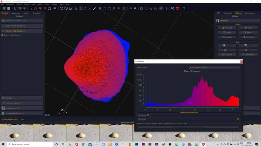
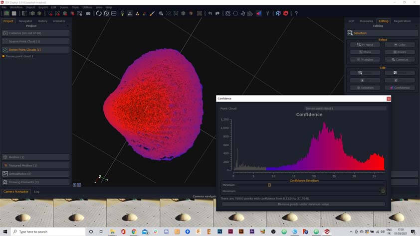
I tried the Confidence Tool in the editing section it makes a sort of topography of the model, this feature allowed me to take out the part that was more than the seashell - but again, I couldn't export a 3D model after this step.
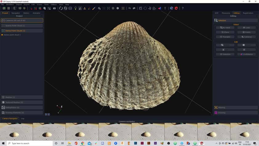
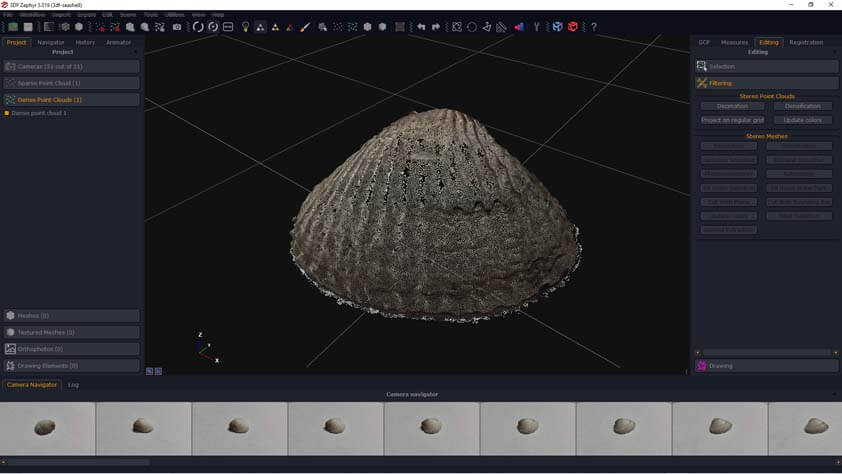
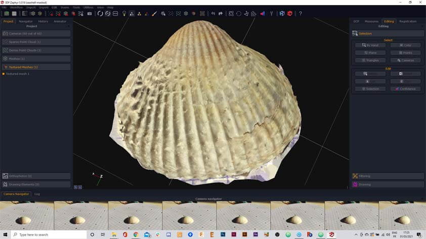
Here is the 3D reconstruction of the seashell :
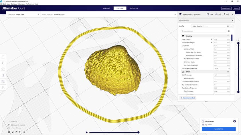
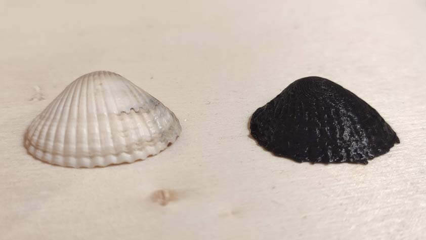
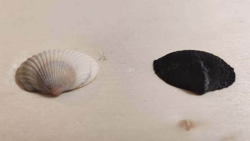
I imported the model in Cura and printed it. The result is missing details, but it is already satisfying regarding the previous results.
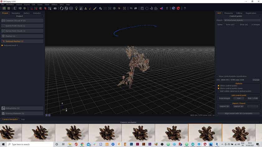
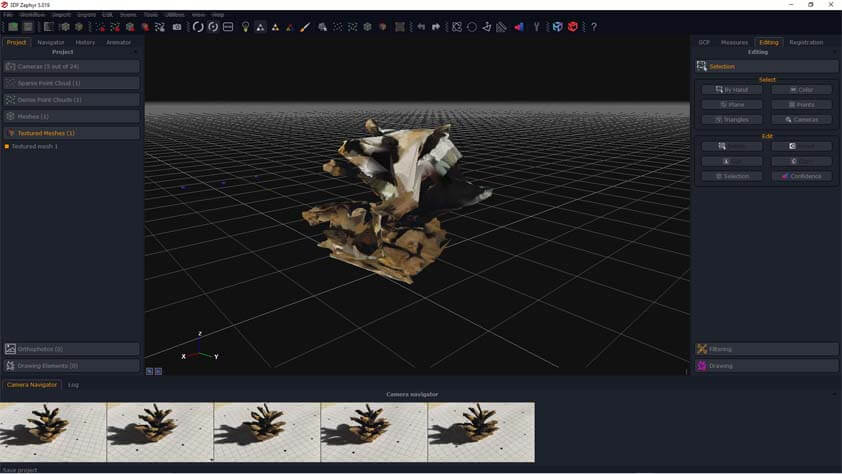
I thought I would do it again with the pinecone and using the masking feature, and I thought it would work this time. The first image I saw on the software was already much more detailed than my previous atttempts, but I turned the model around, and only the half of it had been reconstructed. 5 images out of 24 were used by the software. It demonstrates that the quality of the scan does not rely on using an high amount of images of the object. So far I learned that it does rely on the quality of the images, of the light exposure, on the fact that these good images has to overlap on each other. A good result also depends on the abilty of the software to detect the tracking around the object using images, a pattern that is irregular as a background is useful, its irregularity will be easier to track. The framing is also very important and wil impact the result, when using the photogrammetry process with a turntable it is best to avoid framing out of the turntable zone : the object is moving, but the background is not, the tracking is therefore more complicated to process, and it creates a lot of artefacts. Using the mask tool is also helping to prevent this.
A 3DF Zephy capability is to give it video and it exports images out of it. I thought it could be useful to try, as the camera is not moving maybe the tracking will be more accurate.
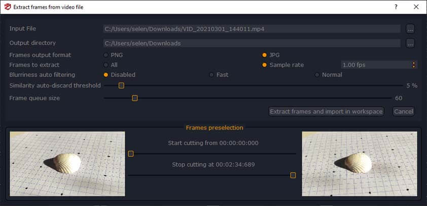
And yes it was, it is the best result I got using these softwares so far - I'll have to find how to edit and export mesh using 3DF Zephyr (in the 12 remaining days of my free trial).
☛ Textures
This part is a Bonus, what textures from different 3D sofwares look like.
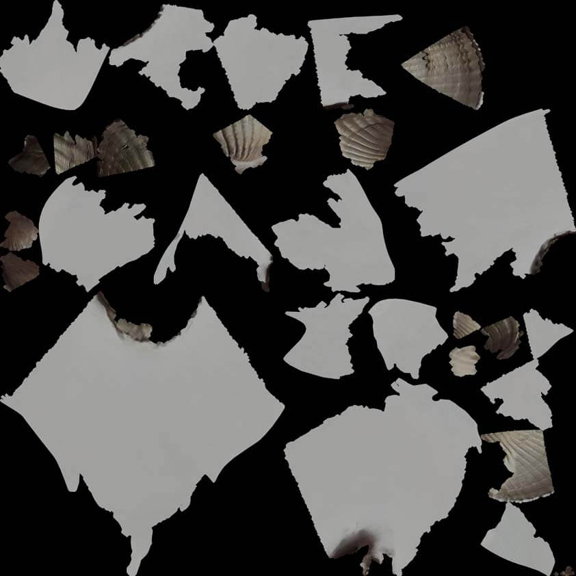
AutoDesk ReCap Textures
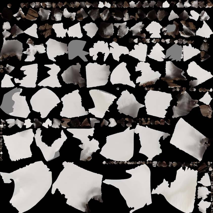

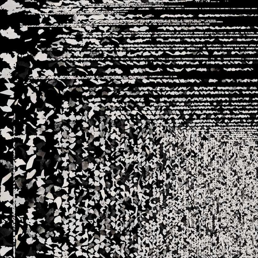
AliceVision MeshRoom Textures
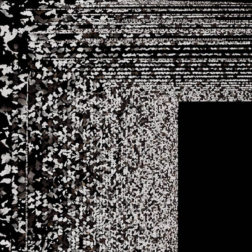

Microsoft 3D Builder Textures