Week 3 : Computer Controlled Cutting
☛ Group Assignment
☐ 1. Characterize your lasercutter's focus, power, speed, rate, kerf, joint clearance and types
☛ Individual Assignment
☐ 2. Cut something on the vinylcutter
☐ 3. Design, lasercut, and document a parametric construction kit, accounting for the lasercutter kerf, which can be assembled in multiple ways, and for extra credit include elements that aren't flat
▸ Introduction to the Roland GS-24 Vynil Cutter machine
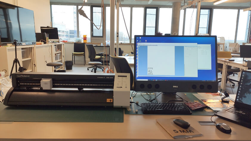
How it works
A VynilCutter is a 2 axis computer-controlled machine that uses an axis to carry and move a blade, while the ohter axis is moving a sheet or a roll of a thin material. The machine can cut out shapes using vector graphics, and even draw by replacing the blade by a pen. Its most known application might be cutting vynil signs into stickers, but it can also be used to design flexible PCBs, Origamis and Kirigamis design, Silk-screen printing, so this is a machine offering a lot of possibilities.
Machine specifications
- Sheet/roll width : up to 700mm.
- Maximum cutting area : 584 x 25000mm of operable range. The accuracy guarantee range is 1600mm.
- Thickness : up to 1mm. But it is not recommended to cut up this thickness of paper, materials that are too dense or abrasive may damage the blade.
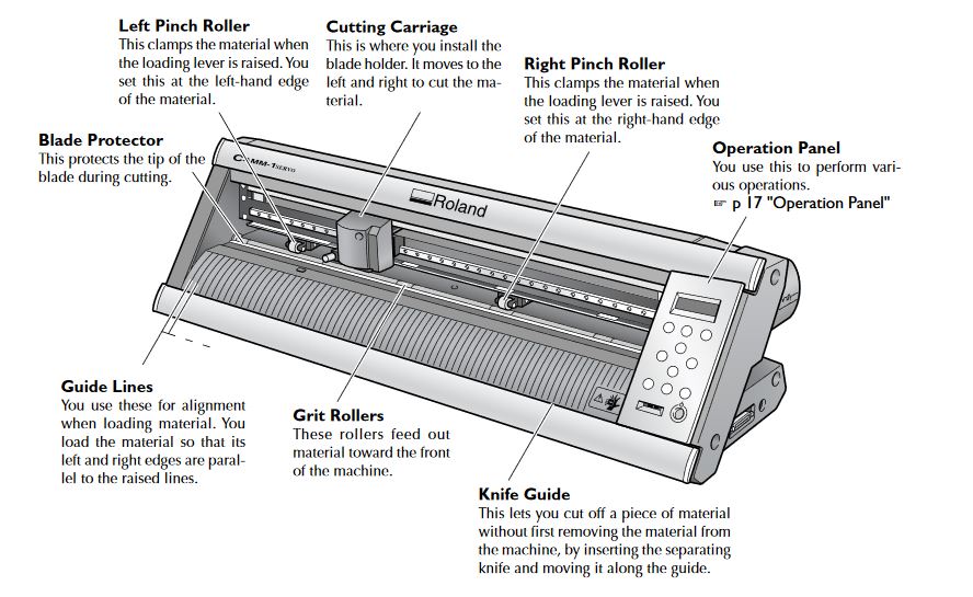
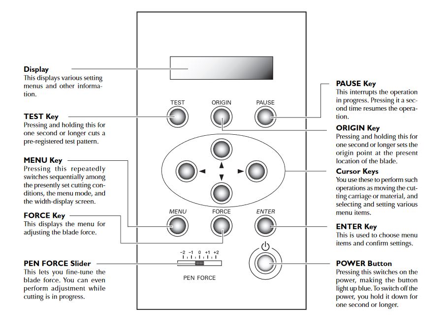
Machine components
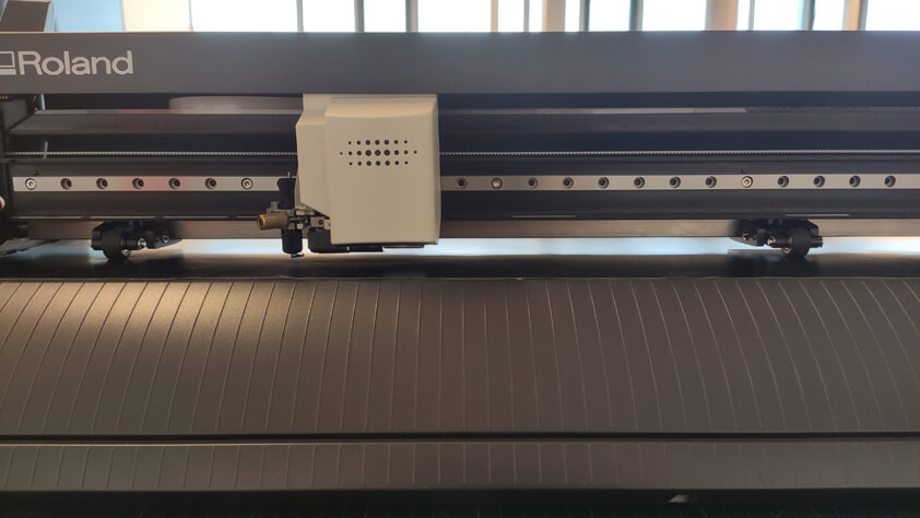
- Cutting carriage : Holds the cutter holder and moves on the right and on the left along an axis.
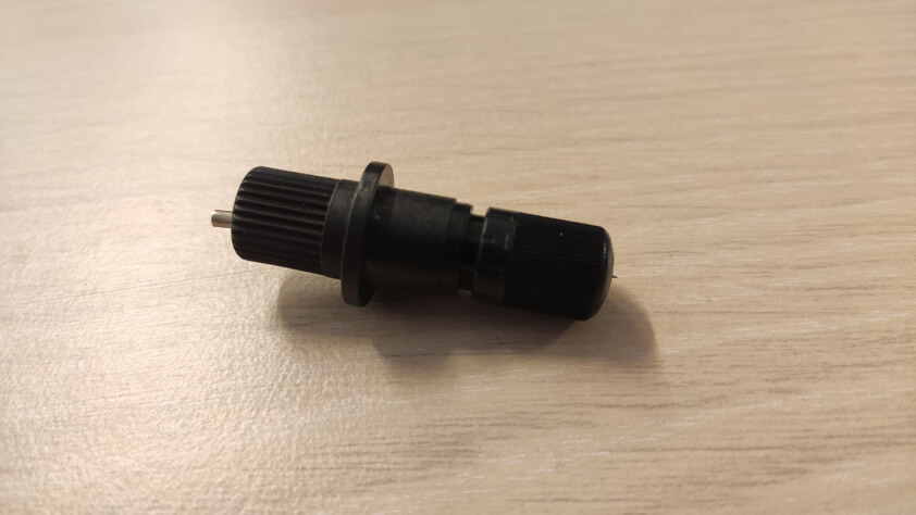
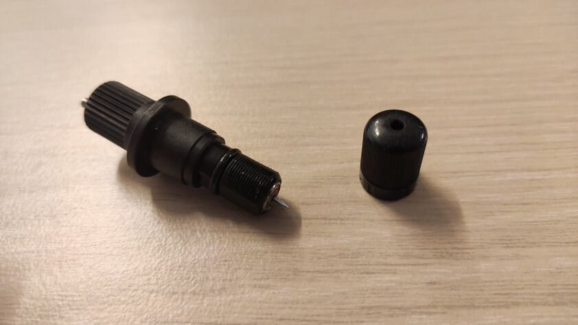
- Cutter holder : Carried on the cutting carriage, holds the blade or the pen holder. It cuts between the pinch rollers.
- Pinch rollers : Rollers that are manually moved along an axis to maintain the paper.
Here are useful images with details about this vynilcutter machine and its control panel. And there is a complete tutorial to use it here, it is where I took those images.
▸ Using the Roland GS-24 Vynil Cutter machine
Roland CutStudio
Roland CutStudio is the software used by the machine to process images before cutting them. We used a plug-in to import sketches from InkScape, here is the github repository regarding this plug-in. Plug-in to export directly from Corel Draw and Adobe Illustrator are existing too.
Steps
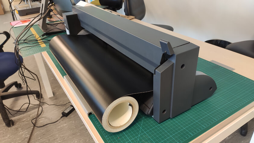
- Placing the sheet
- Preparing the files and importing them to Roland CutStudio
- Setting up the cut parameters
- Cutting
- After Cutting
Placing the sheet
Preparing the files
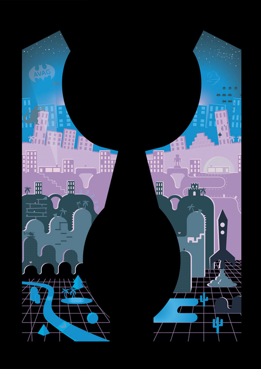
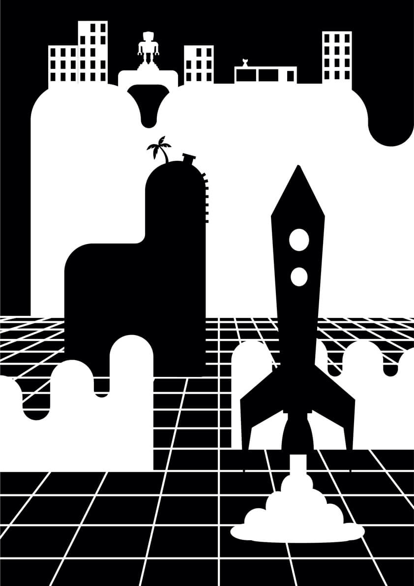
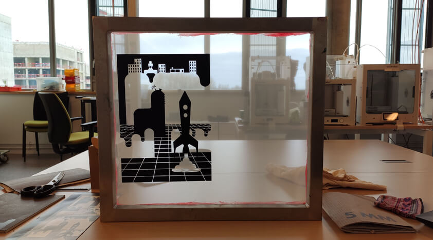
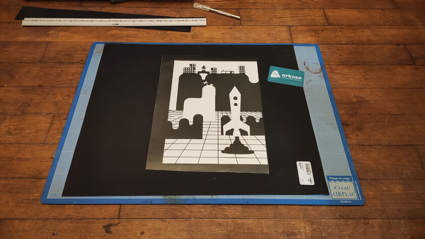
I reworked an illustration I did last summer using Illustrator, I selected a detail, cleared the illustration from effects and masks and made a monochrome version out of it.
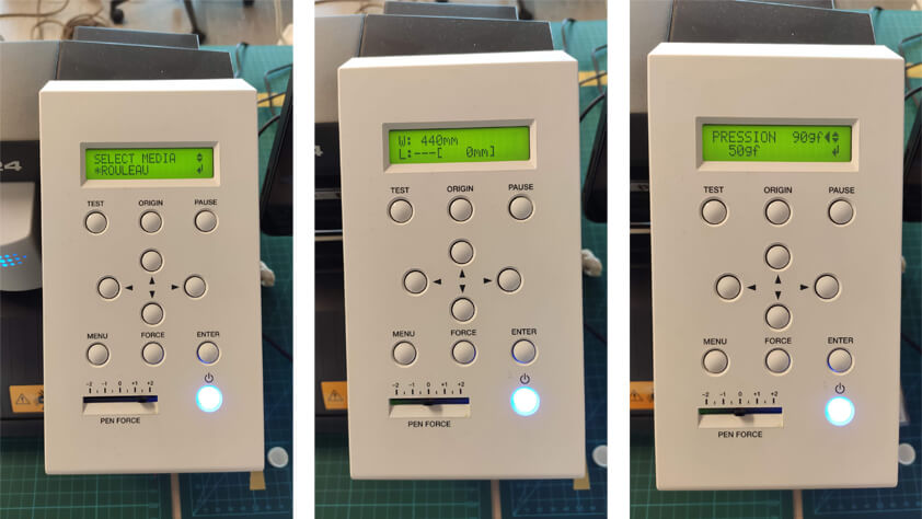
Setting up the cut parameters in Roland Cut Studio
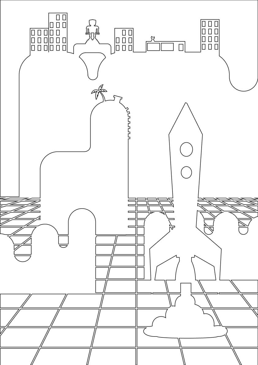
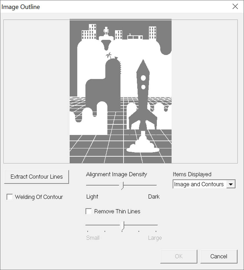
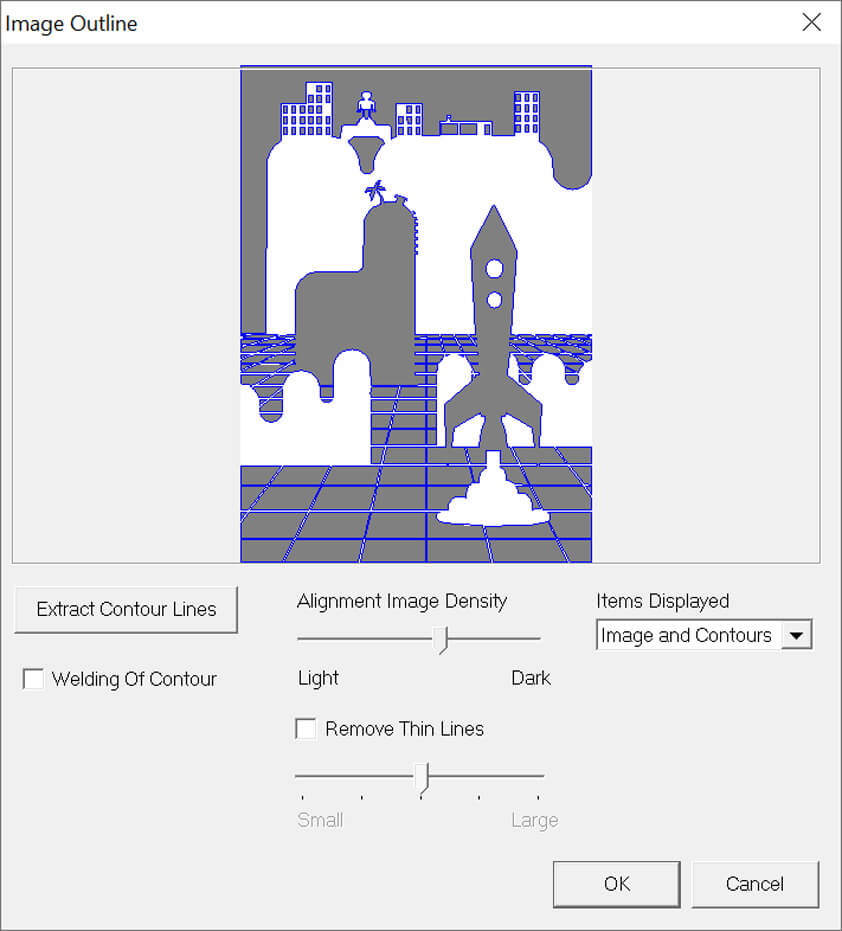
When the files are ready we can import them in Roland Cut Studio, and select the "Image Outline" tool to outline vectors from our image. When the image preview is fine, click "Extract Contour Lines" and the "Ok" button appears.
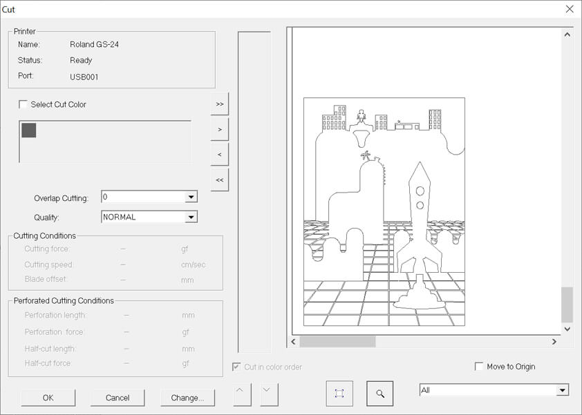
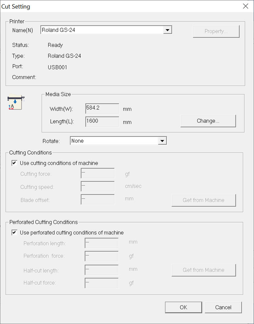
Click on the cut icon to open the cutting parameters, as I did tests with the machine settings before I clicked "Use cutting conditions of machine". Then click "Cut" and the job is sent to the machine.
After Cutting
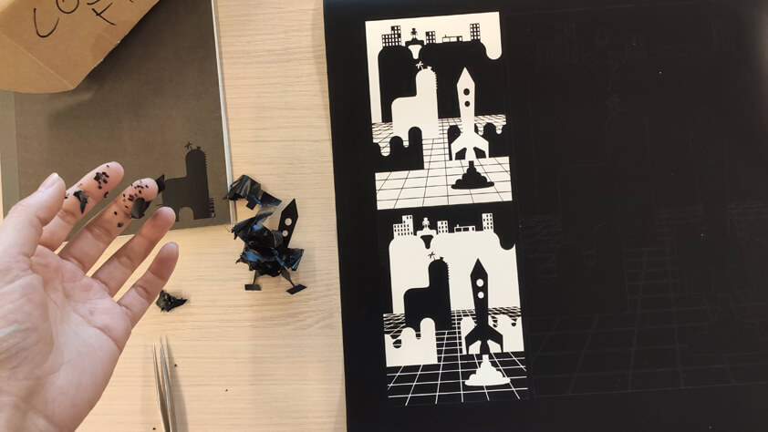
After cutting it is time to remove the sticker part we don't need. We use tweezers to do so. Here is a video my illustration being peeled.
A thick repositionable adhesive is used to transfer the sticker from its back paper to the final support. We use a tool to remove air bubbles.
Here is a video showing the sticking process to the silk-screen.
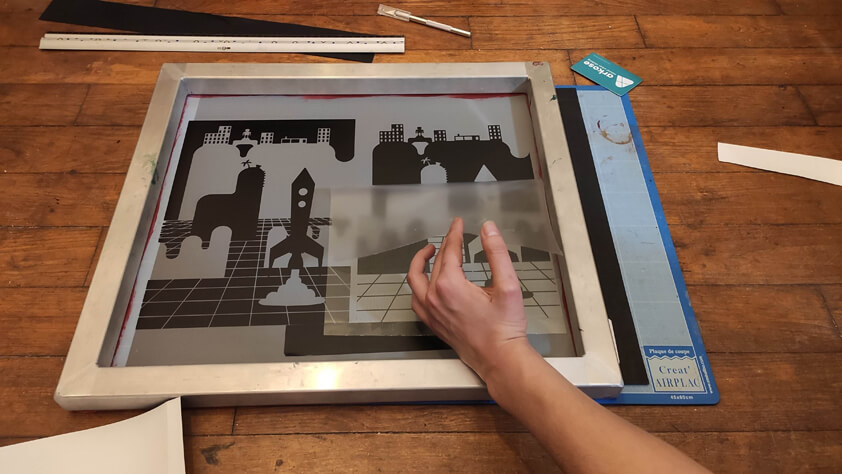
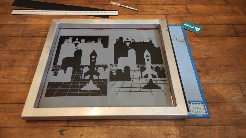
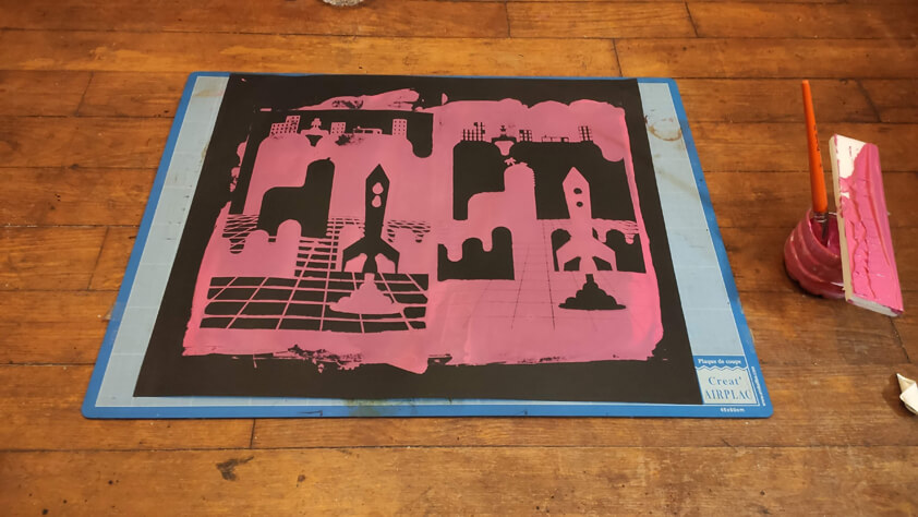
▸ "Silk-screen printing" with vinyle sticker
Here are some images showing the steps I went through - I have never silk-screen printed before so I only know the basics about it, plus beside the screen that I found in the Fablab I don't have the proper tools. I used dense foam that I double-tapes to make more rigid, in order to make something similar to a screen printing squeegee.
- Preparing the material
- Taking the vinyle off its back paper
- Placing the vynile and its support on the screen
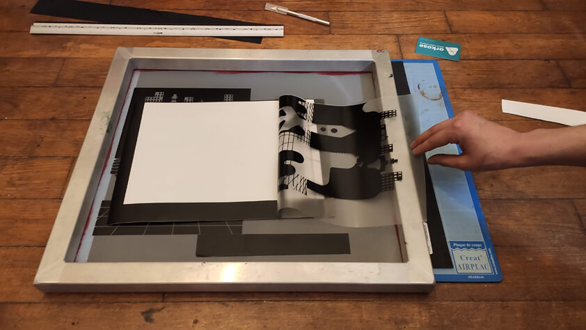
- Taking off the repositionable adhesive
- Preparing the material
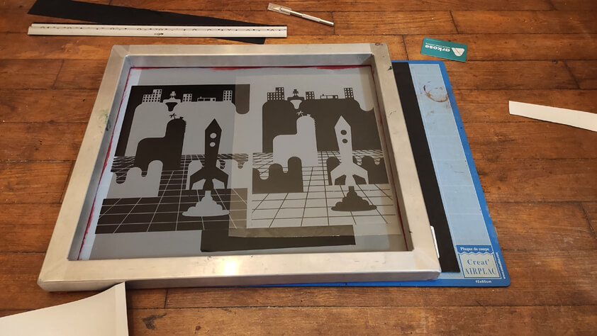
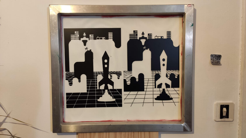
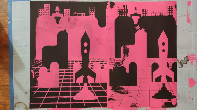
- Screen-printing
- Note : it is hard to wash the screen after the process
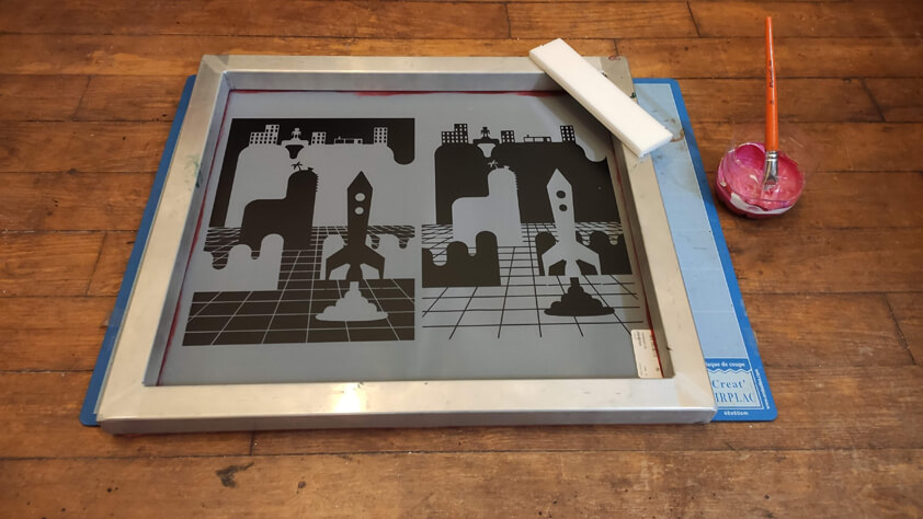
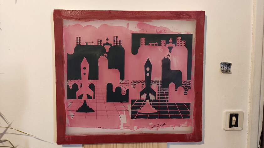
- I did a second try where I tried to make less pass with the acrylic paint - it was complicated to make a single and efficient pass (tools issues) but it was already way better than the first test.
▸ Introduction to the Epilog Fusion M2 40 Laser Cutting machine
How dangerous it can be
Using the laser cutting machine is literally "playing with fire", when using this machine it is important to watch and watch out, to take great care that the ventilation system is on before starting a job and to face the machine while it is working. The laser ignite the material, so it can catch fire and burn what's around basically. The fumes can also damage the lens.
How it works
A Laser cutting machine moves a laser-carriage along 2 axis, while a third axis is used to support the material on the right level according to the laser beam. An air comressor removes heat and combustible gases from the cutting by directing a constant stream of compressed air over it. There are different types of lasers, the Epilog Fusion M2 40 has CO2 and a Fiber laser.
The CO2 laser is generated from gas mixtures electrically stimulated, the Fiber laser are amplified by a special glass fibers, the first can be use to cut and engrave through several types of woods, cardboard, acryclic, and the second is most used to mark platics, PCB for instance.
Machine specifications
- Double source laser : CO2 and Fiber
- LaserCutting area : 1016 x 711mm
- Maximum Power : up to 75W for CO2 laser, up to 30W for Fiber laser
- Material thickness : up to 6mm, over 6mm it is better to use the CNC.
It is important to know what materials you can't use on these machines, because in the melting process these materials will emit unsafe fumes and gasses, catch fire easily or damage the machine (the lens has to be treated with care, disfunctional lens = disfunctional results). And here is a link detailing a wide variety of materials you can't cut, as well as those you can, with care.
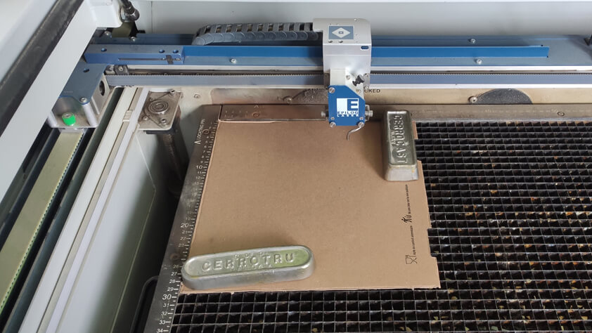
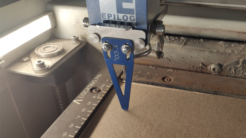
Material placement & Laser Cut Focus
- When placing the material on the LaserCut machine's bed we have to make sure it is flat, we can use weights to place on the mmaterial. Be careful with the height of those weights, they must not be in the laser carriage way.
- To focus the machine we use a tool for that, make sure to select the CO² laser focus tool, the Fiber one has a different size.
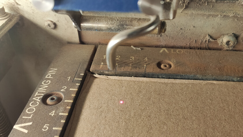
- The laser is not visible, a red dot can help to visualize where it is on the material.
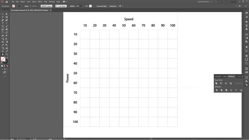
Group assignment
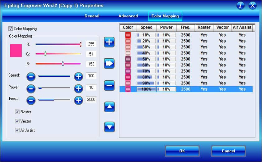
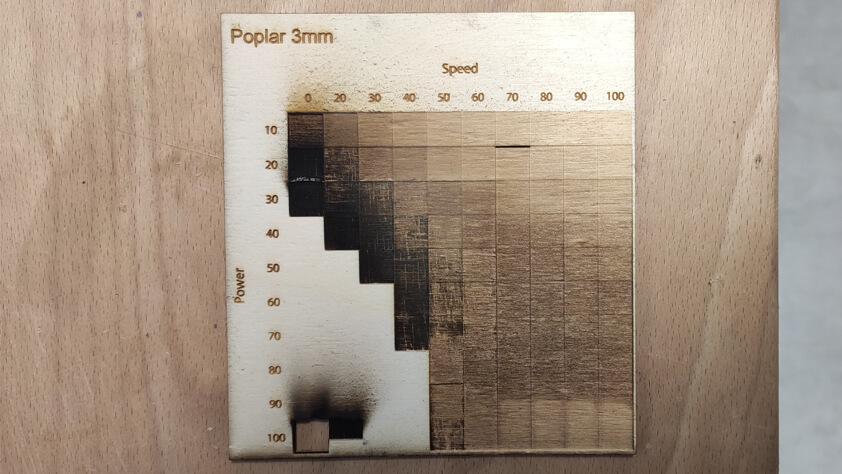
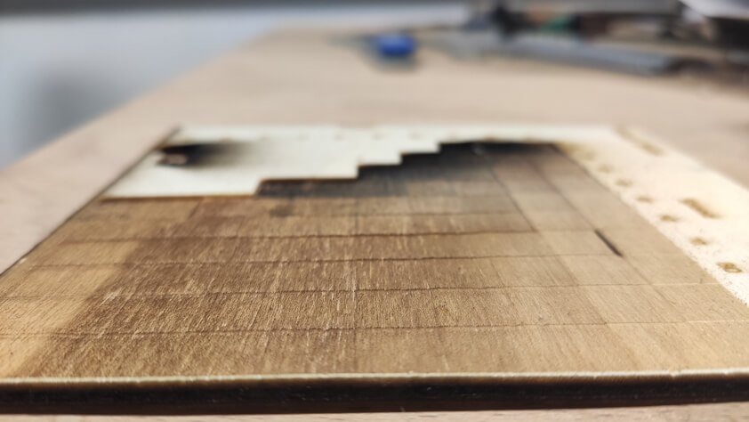
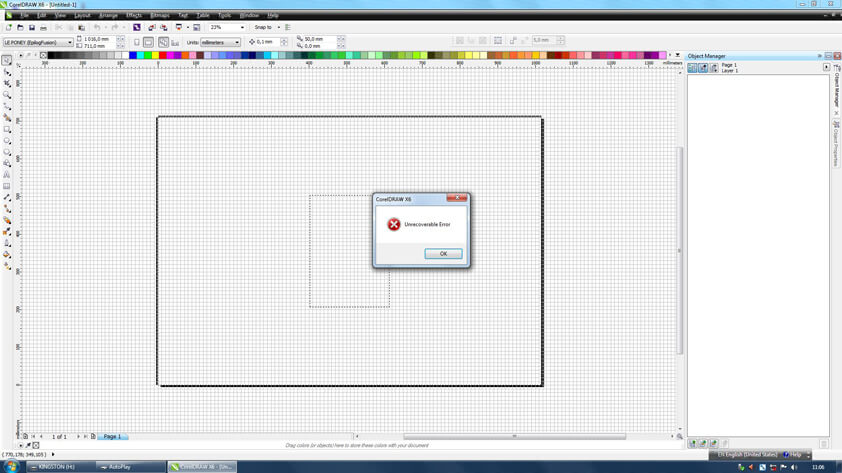
During the group assignement we thought of a way to test several parameters of the power and speed of the machine. I created a file on Illustrator with squares of 10 x 10 mm and I imported it in Corel Draw. I used the color mapping menu to "print" different paramerters at the same time.
A first test was made on thin cardboard, 1,5mm thick. But it quickly came through the material when the power and the speed were low.
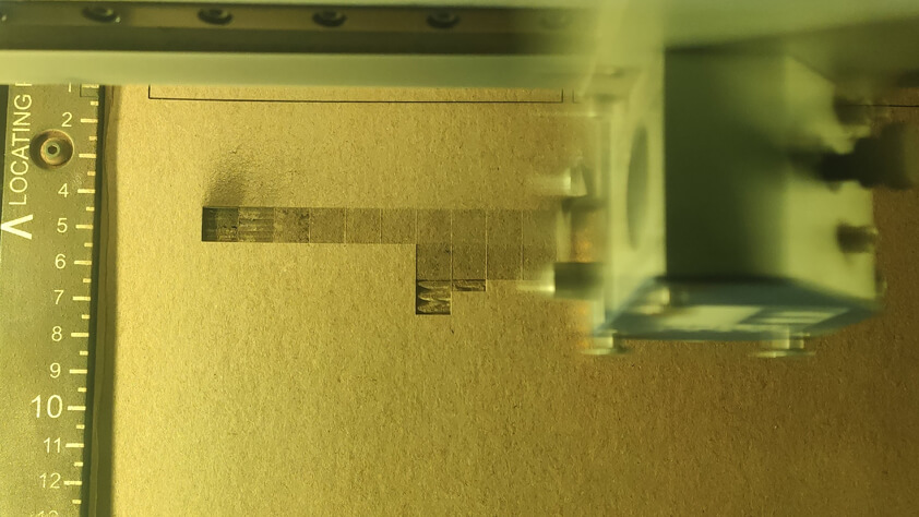
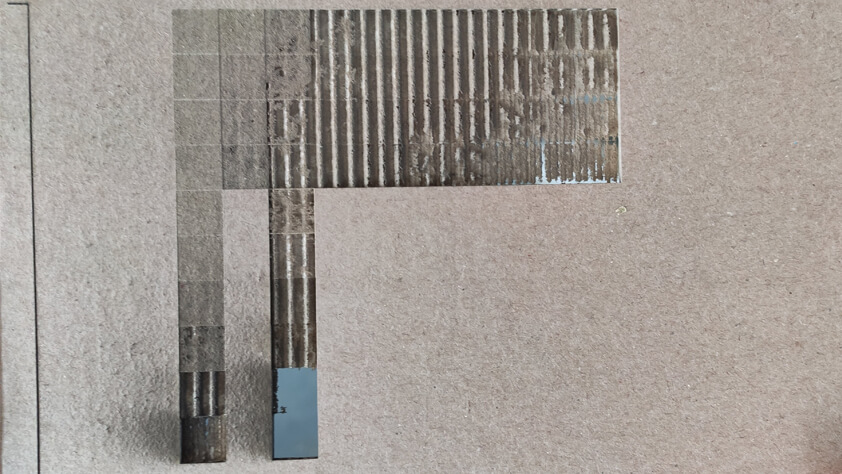
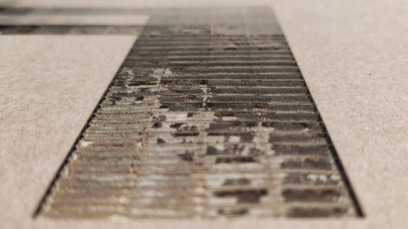
We made a second try using 3mm poplar wood, when the power was increasing at a low speed, it burned the wood. The process of laser cutting this file was very long even using the color mapping tool.
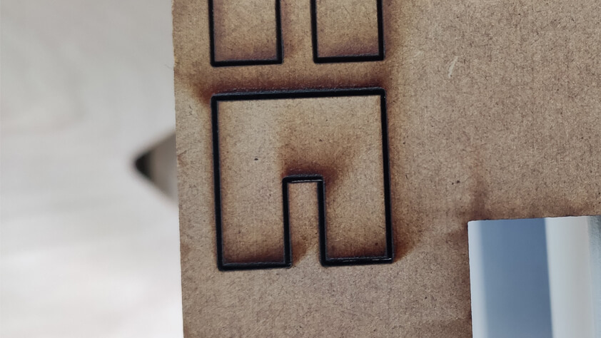
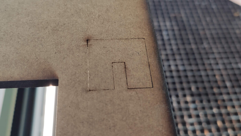
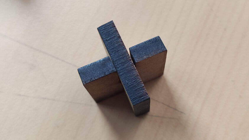
Kerf
To see how much kerf was, we cut a simple joint and tried to assemble it. We used 5mm MDF and had troubles to go through, it took 4 passes to cut it with those parameters, the kerf increased along this process.
Simple parametric press-fit shape
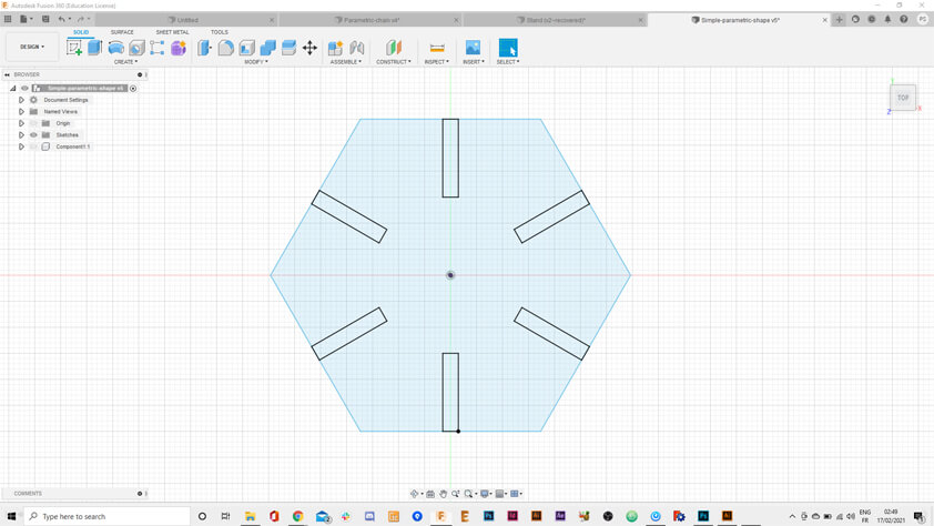
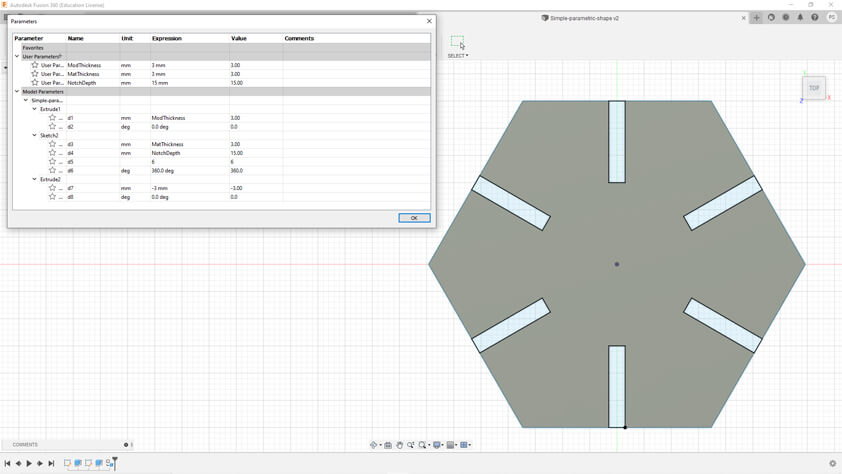
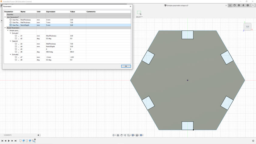
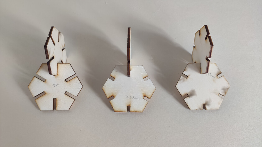
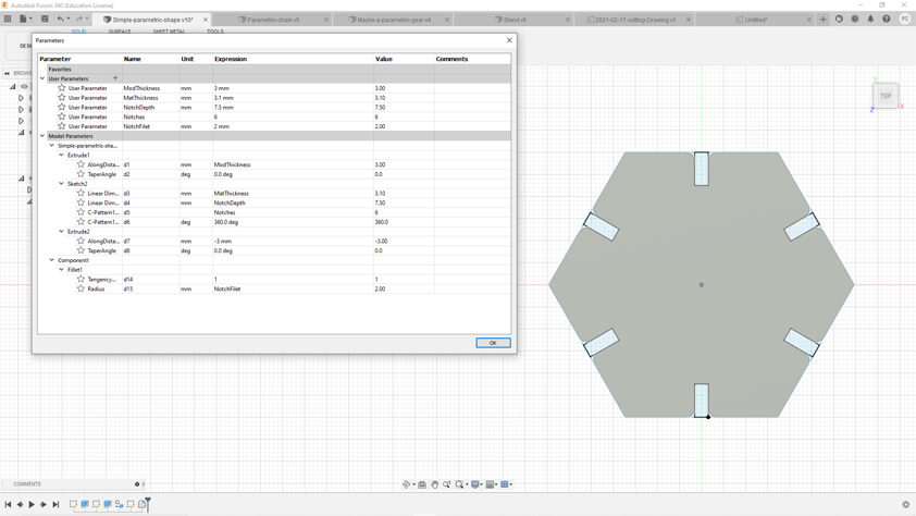
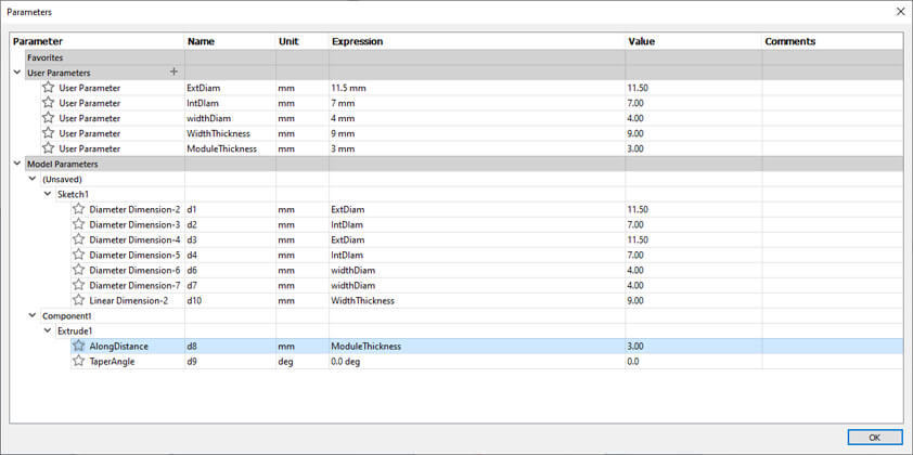
I designed a simple parametric shape using Fusion 360, I made a 6 faces polygon and cut notches through it. I created User Parameters to make this shape parametric, so its size, and thickness, and the notches and ther widthe and depth are parametric. I will re-take a look at this to make the number of faces of the polygon parametric too.
I had trouble to export a DXF file from Fusion, I did it from the Design menu and this 3 dimensionnal DXF could not be read by Corel Draw.
The right way to do it is to switch to the Drawing menu and select "from design". From this interface I imported a pdf file that I imported to Corel Draw.
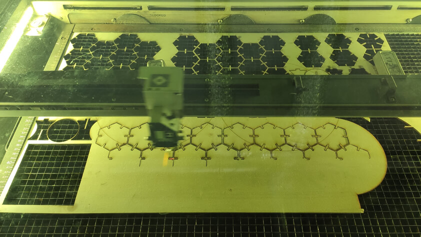
I entered the laser cutting parameters in the print menu and made several tests to find the right notch size in order to have a good clip when assembling the pieces.
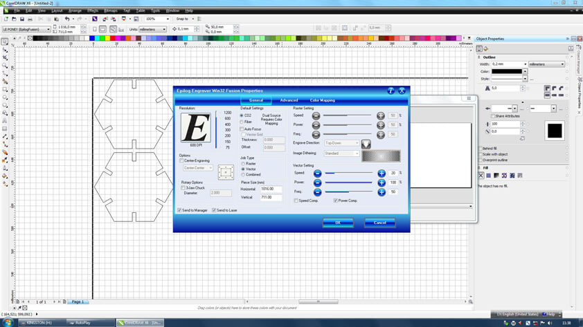
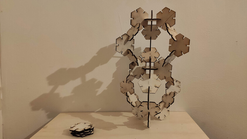
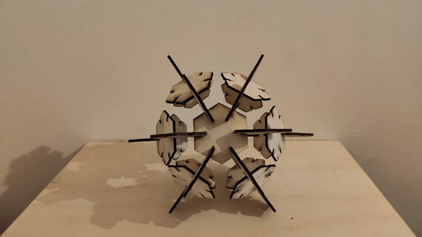
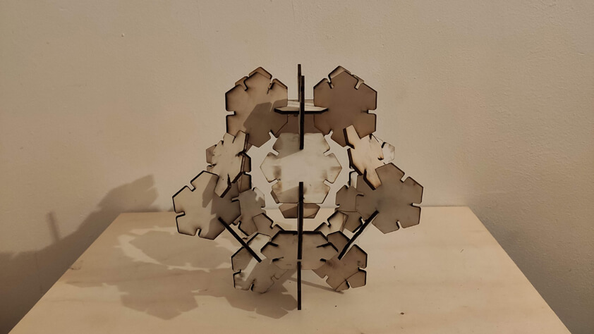
Once I had the right parameters (lasercutting parameters on the Epilog Fusion M2 : 20/100/50) I cut twenty of these shapes and began to try what kind of shapes were possible to make.
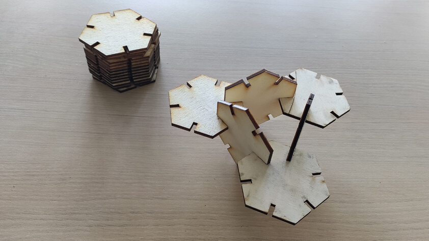
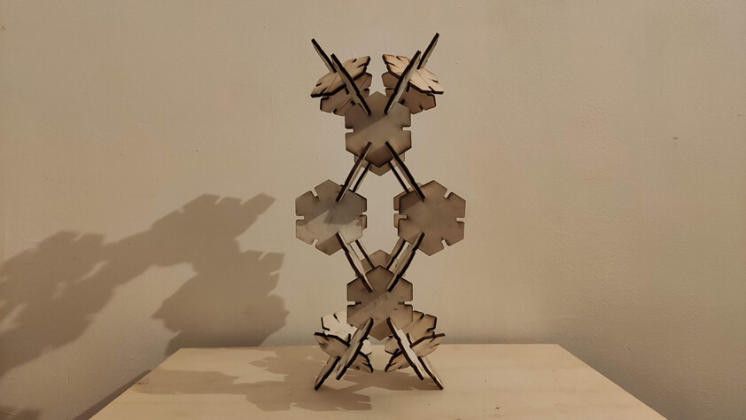
Shape 1
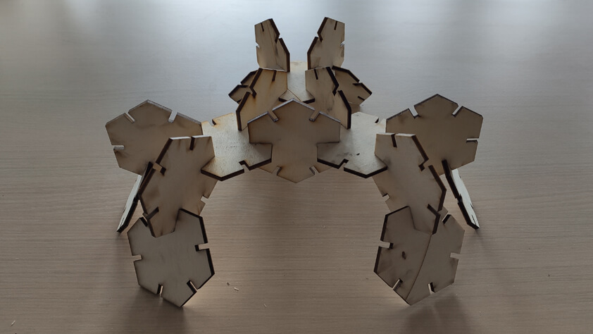
Shape 2
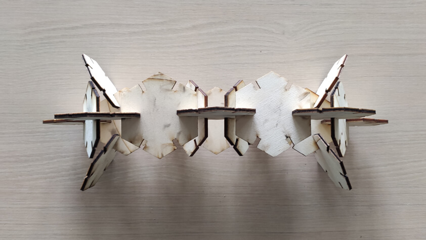
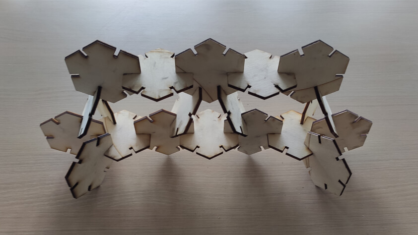
Shape 3
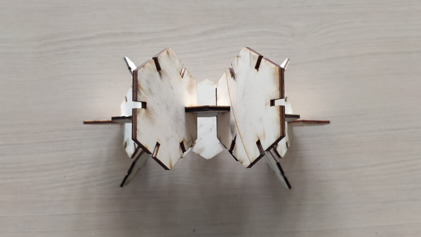
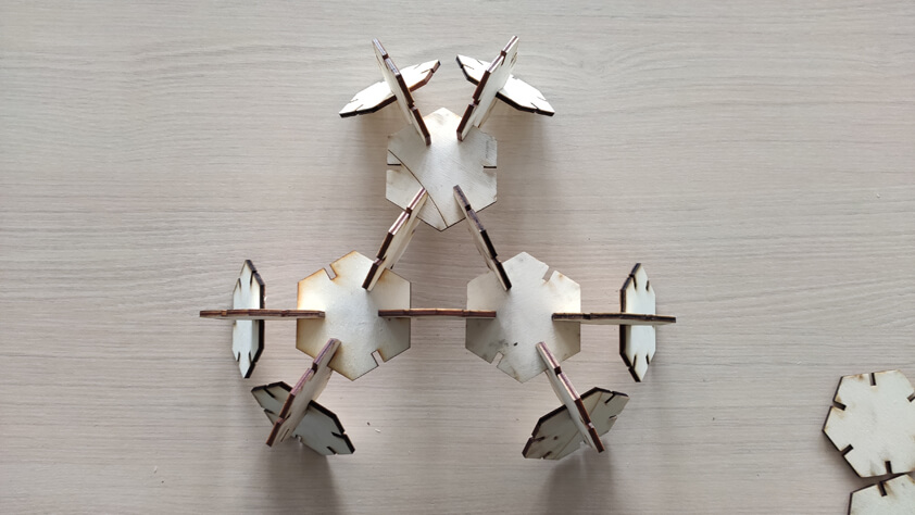
Adding filet
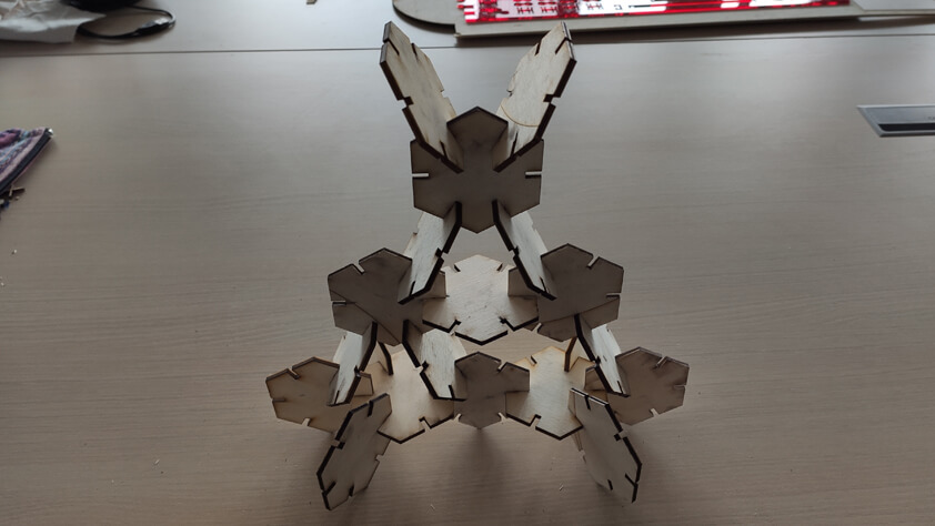
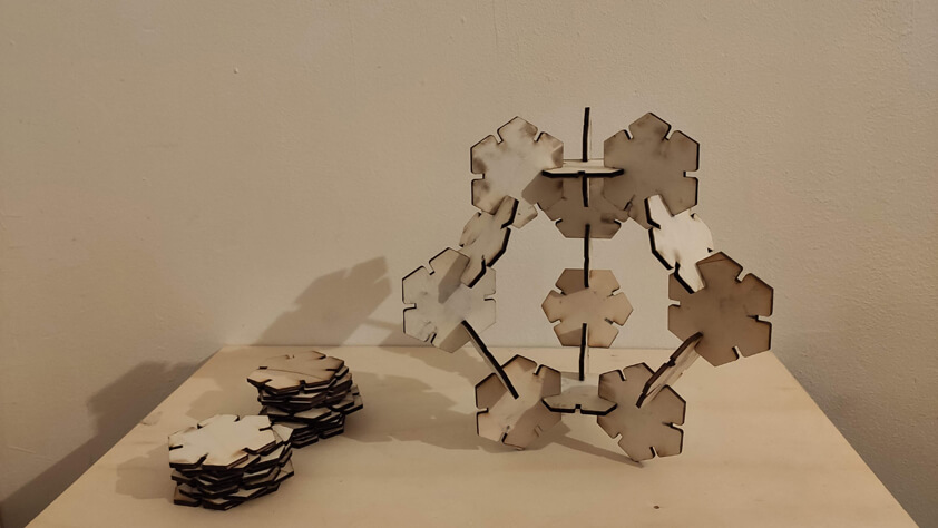
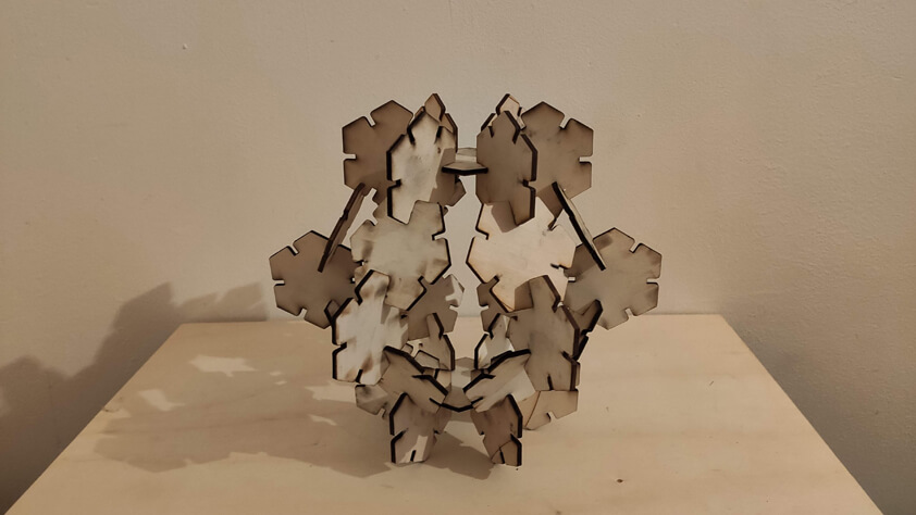
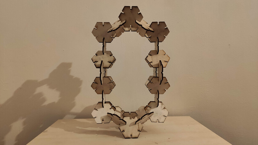
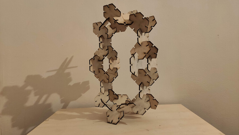
I added a filet to the notch to make the assembly process easier, here are a few structures that are possible to make with this very simple shape.
Shape 4
Shape 5
Shape 4
Not totally parametric test yet
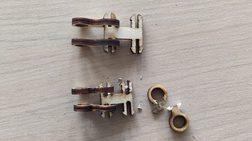
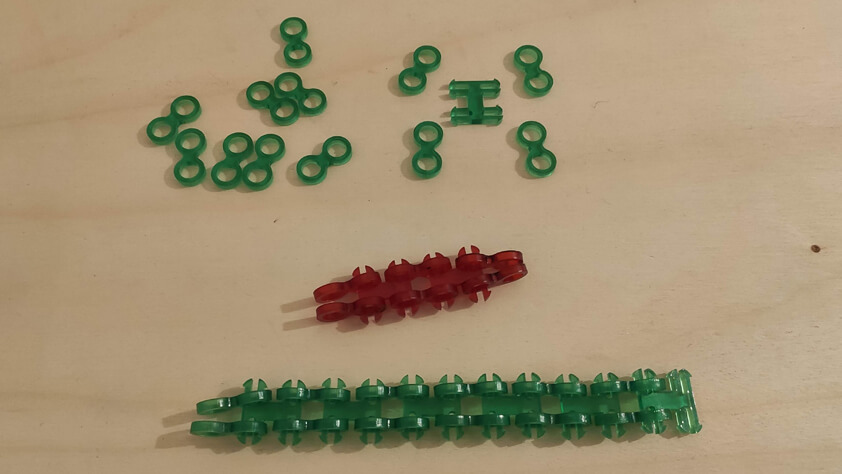
I made an another test because I wanted to make a belt using only the laser cut machine. I made the first tests using popllar and cardboard. It worked in principle but the fibers from those materials make that it is hard to get a smooth movement.
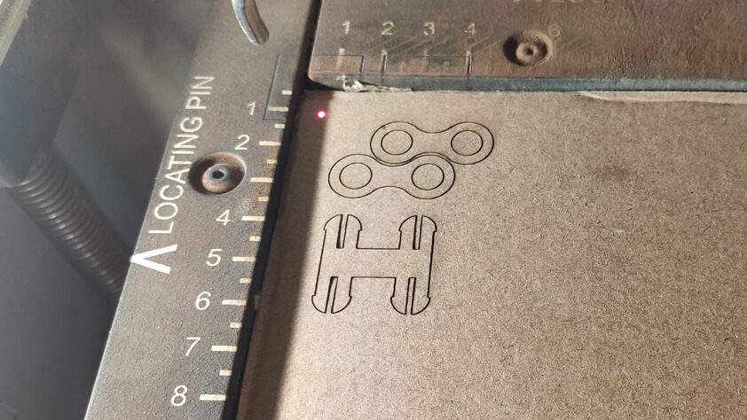
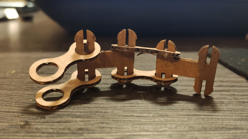
Here is a video showing how these tests are behaving when moved.
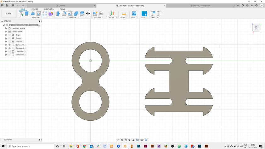
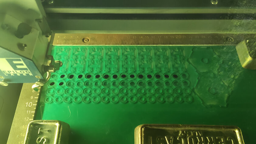
I made more tests, first by trying to make this shape a parametric one, it succeded for the rounded shape, but I'll have to give another try to the other piece.
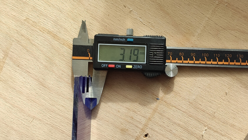
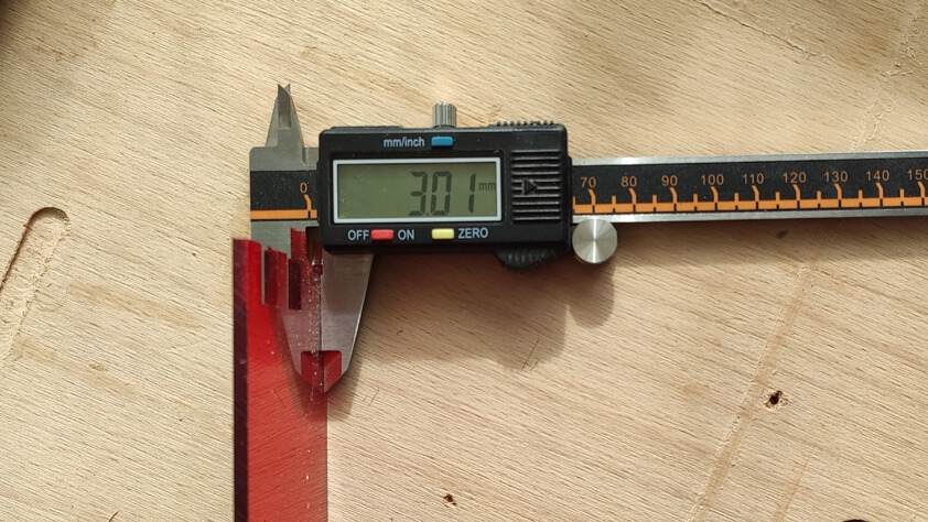
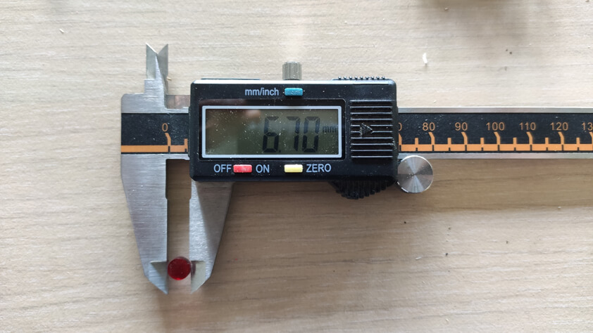
I measured the blue and red pmma thickness, and they're not the same size because of the protection sticker on the blue PMMA.
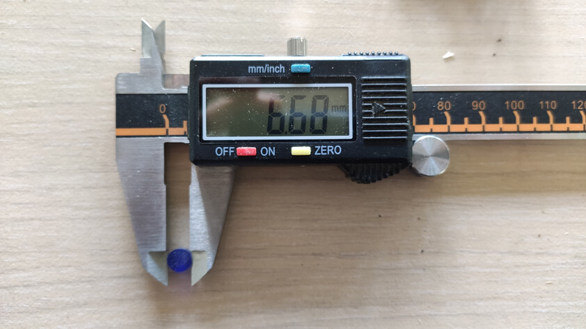
I measured the blue and red pmma after the laser cutting (laser cutting parameters for the EPilog Fusion M2 : 15/100/10 x2), and the kerf is not exactly the same size.
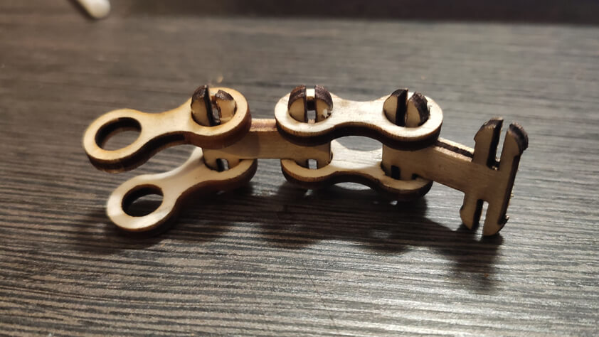
The first results when assembling the pmma pieces are satisfying the movement is smoother with PMMA than Cardboard or Wood - mainly because of the fibers of these materials creating friction. Nevertheless the PMMA is pretty fragile during the assembly process and there was breaking pieces involved. A good tip is to use the "shape of the laser", it is not a straight line, it creates a bevel in the material and it helps the linking piece to go through the rounded one.
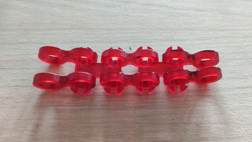
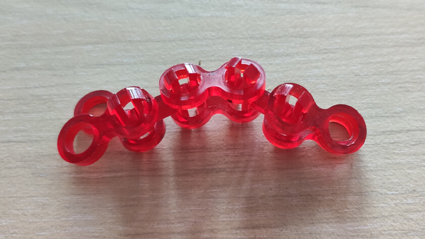
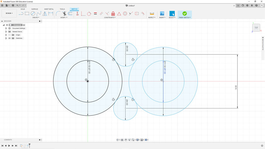
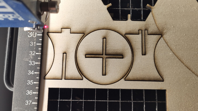
More pieces to make a longer chain and test if it would work with a gear. I used the simple parametric shape above to design a gear adapted to the chain design. I also draw a parametric stand to hold the gear.
Here a satisfying video of the first test for this laser cutted timing-belt-to-be :