Mechanical Design,Machine design
Assignment content:-
- Project introduction.
- Bill of Materials.
- component description
- circuit connection
- Grbl Controller.
- Universal G-Code Sender.
- Polograph.
- 3D design and parts
- full assemble and final test
Machines used:-
- 3D printer.
- Power supply.
- Digital multimeter.
- Leaser cutter
- saw
Project introduction.
I and my group participant have discussion with our remote instructor Mr sibu for making a vertical plotter he has given us the basic concept and idea to make vertical plotter using arduino and stepper motor. My group project is a hanging drawing machine (vertical plotter) that moves its hand in two axes (X, Y). The hand conists of a pen attached to a 3D printed holder that connected to two stepper motors from the right and left sides. The machine should be attached vertically to a board and being controlled by a g-code.
The aim of this machine is to enable the user to draw anything on a board or a wall. Requirements are simple as the user should just fix the machine on the panel want to draw on and enter the size of the drawing area and machine specifications.
Following are the details documentation for the hanging plotter. Work flow for the making machine.
Bill of Materials.
- Arduino UNO
- Power adapter
- Servo motor
- Stepper motor
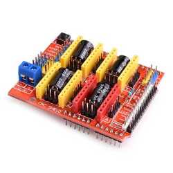
- CNC shield
- Stepper motor driver
- Heatsink for the stepper motor driver
- Toothed belt
- Power supply
- Digital multimeter
- Screwdriver
- wooden frame
- Pend & paper
- 3d printed pen holder
- 3d printed steppter motor holder
component description
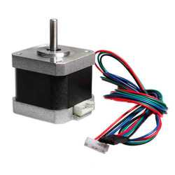
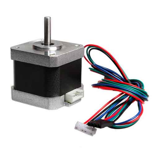
- NEMA 17 most common stepper motter,NEMA 17 is a hybrid stepping motor with a 1.8° step angle (200 steps/revolution). Each phase draws 1.2 A at 4 V, allowing for a holding torque of 3.2 kg-cm. NEMA 17 Stepper motor is generally used in Printers, CNC machines and Laser Cutters.
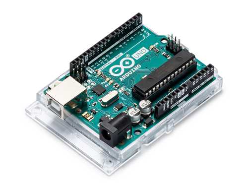
- Arduino Uno for GRBL and Polograph Programming.The Arduino Uno R3 is a microcontroller board based on a removable, dual-inline-package (DIP) ATmega328 AVR microcontroller. It has 20 digital input/output pins (of which 6 can be used as PWM outputs and 6 can be used as analog inputs). ... The R3 is the third, and latest, revision of the Arduino Uno.
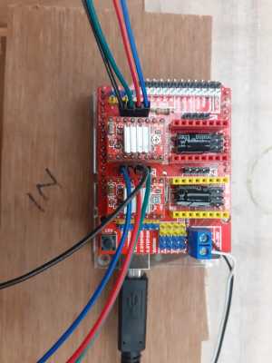
- Stepper Shield a COMPLETE hardware for CNC Motion (gives you all kinds of options for a machine with spindle rpm included) The Arduino Motor Shield allows you to easily control motor direction and speed using an Arduino. By allowing you to simply address Arduino pins, it makes it very simple to incorporate a motor into your project. It also allows you to be able to power a motor with a separate power supply of up to 12v.
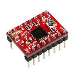
- A4988 Stepper Driver2 needed comes with heatsink to prevent overheating.The A4988 is a microstepping driver for controlling bipolar stepper motors which has built-in translator for easy operation. This means that we can control the stepper motor with just 2 pins from our controller, or one for controlling the rotation direction and the other for controlling the steps.
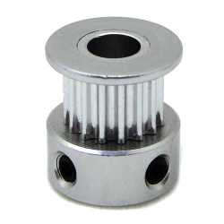
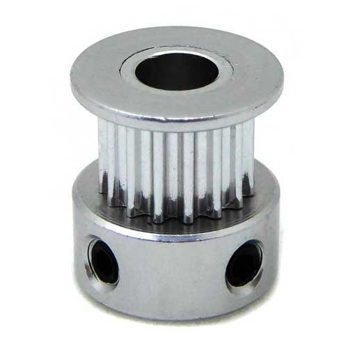
- Stepper pulley teeth attach to your motors to be able to control the penholder gondola
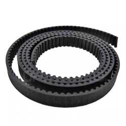
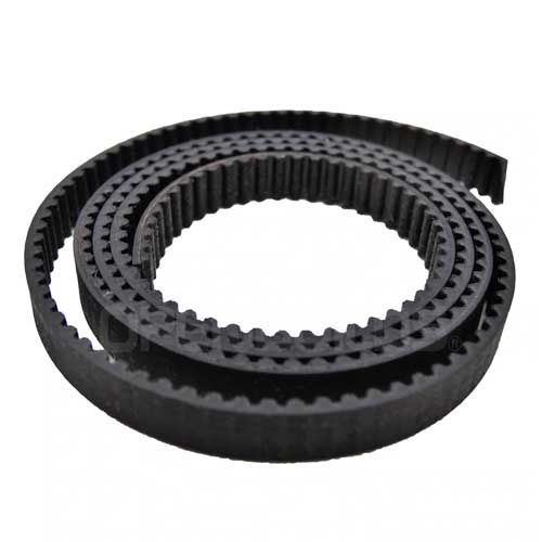
- Stepper belt long enough for the size of your print
- Power Supply 12V power supply.
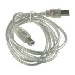
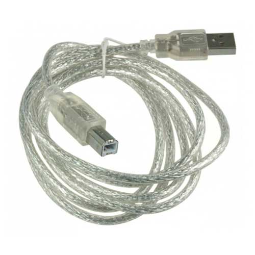
- USB A-B Cable a long one is good depending on where you will be fixing your arduino and the place of your computer
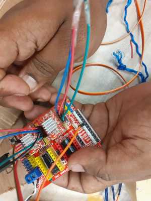
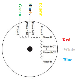
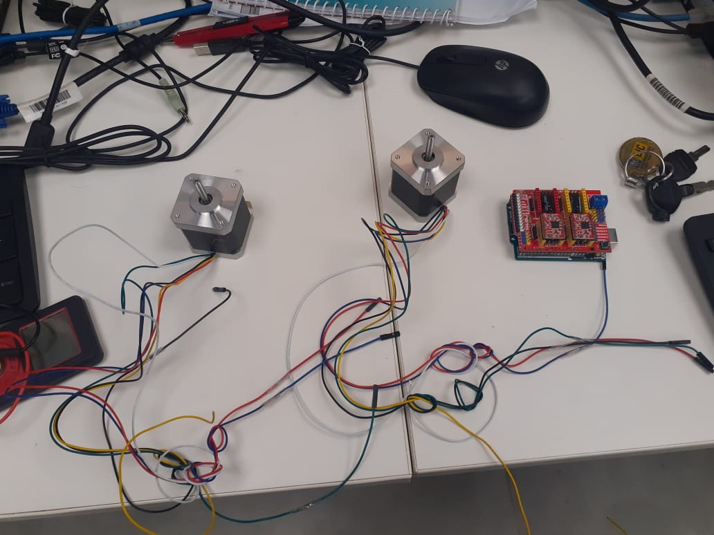
circuit connection
find the 2 pair out six cable in stepper using multi-meter
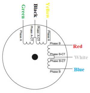
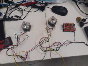
Here is the connection for stepper and servo in the figure. for servo -x, +5v and GND from the CNC shield.
i use power supply where i can adjust current and voltage but 12v to 24 volt i have given 13v and 1Amp
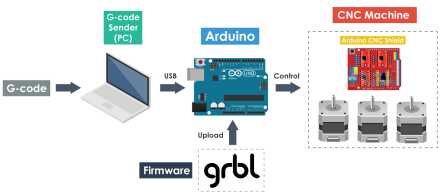
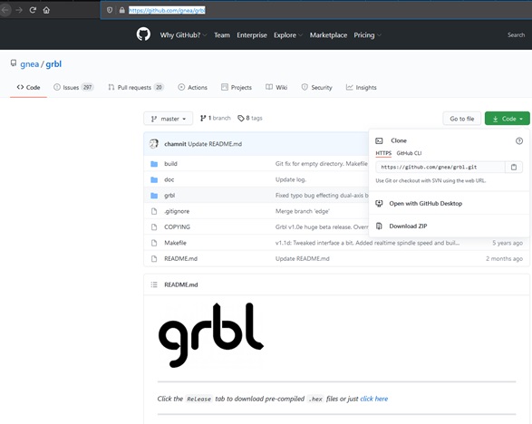
Grbl Controller.
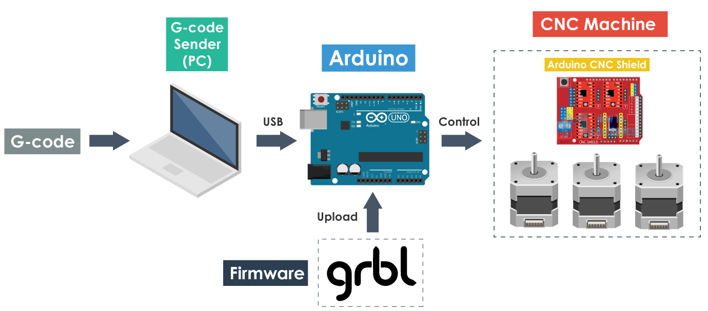
GRBL is an open source software or firmware which enables motion control for CNC machines. We can easily install the GRBL firmware to an Arduino and so we instantly get a low cost, high performance CNC controller. The GRBL uses G-code as input, and outputs motion control via the Arduino .
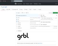
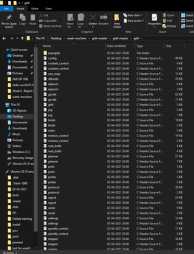
Download GRBL , this is the direct link: https://github.com/grbl/grbl/archive/master.zip
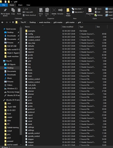
Extract on the desktop the grbl-master folder, you find it in the file master.zip
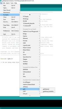
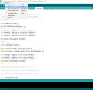
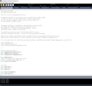
Run the Arduino IDE, currently I’m using version 1.8.1
From the application bar menu, choose: Sketch -> #include Library -> Add Library from file.ZIP…
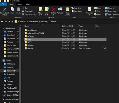
Select the folder grbl that you can find inside the grlb-master folder and click on Open
The library
now is installed and the IDE software will show you this message: The library is added to your library. Check the “libraries
” menu.
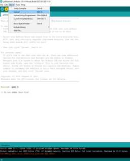
Now that you have installed the GLBR library on the IDE, you must compile and install the sketch GRBL UPLOAD
in the Arduino board.

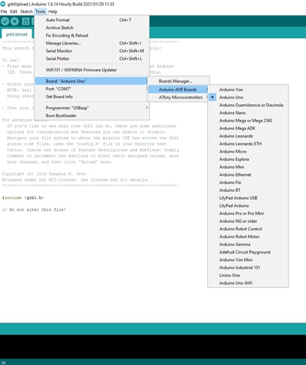
Connects Arduino to your computer and make sure that the IDE
is correctly configured (COM and Board type)
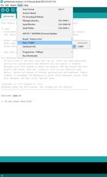
Click on Upload and wait until transferring will finish.
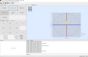
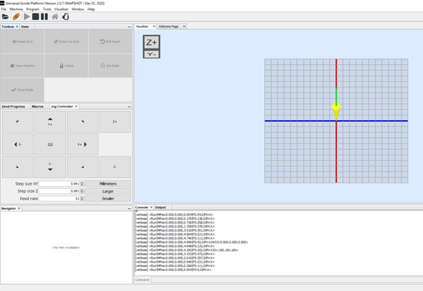
Universal G-Code Sender.
A full featured gcode platform used for interfacing with advanced CNC controllers like GRBL , TinyG, g2core and Smoothieware. Universal Gcode Sender is a self-contained Java application which includes all external dependencies and can be used on most computers running Windows, MacOSX or Linux.
Now you can test your Arduino with GRBL with Universal Gcode Sender,
this is the link of the project on GitHub https://winder.github.io/ugs_website/
and this is the direct link to the download page https://winder.github.io/ugs_website/download/
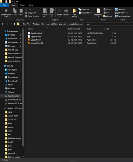
Universal Gcode Sender is a
multi platform program written in Java and requires a version 7 or higher to run.
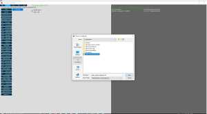
Now after download extract the zip file and open before that you have install java and update so that system can
enable java.
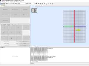
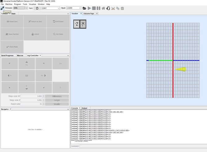
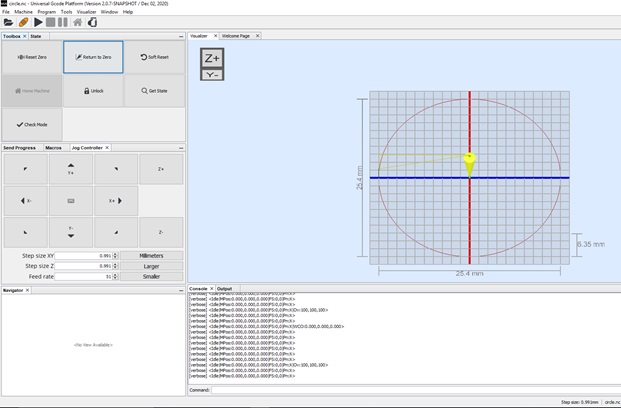
Here the com port 8 it should be properly connect otherwise connection will not establish to UNO
Here i click x+,X- and y+, y- and > which show the movement of motor.After that i upload a g-code file which is a circle its not properly work have error then
my instructor suggest me to use Polargraph source code and processing 2.2.1
Polargraph
A polar plotter also known as polargraph is a plotter which uses bipolar coordinates to produce vector drawings using a pen suspended from strings connected to two pulleys at the top of the plotting surface. This gives it two degrees of freedom and allows it to scale to fairly large drawings simply by moving the motors further apart and using longer strings. Some polar plotters will integrate a raising mechanism for the pen which allows lines to be broken while drawing.
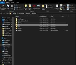
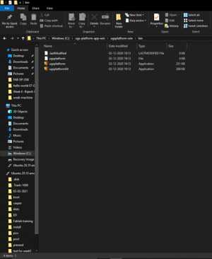
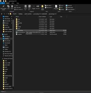
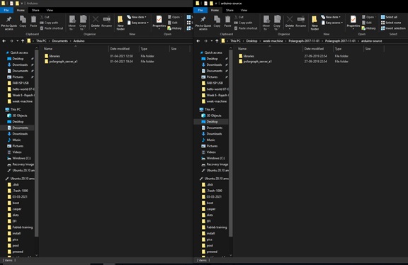
All the necessary files can be found in the repository. The Micro-controller firmware and Application can be found inside this zip file.
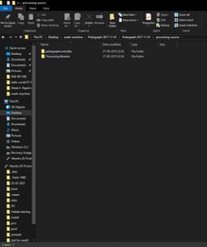
extract the zip file and Also copy the polargraph_server_a1 folder into the Arduino .
- Copy the libraries to be used for the Arduino source code. (Copy the libraries in the Polargraph libraries folder to the Arduino libraries folder.)
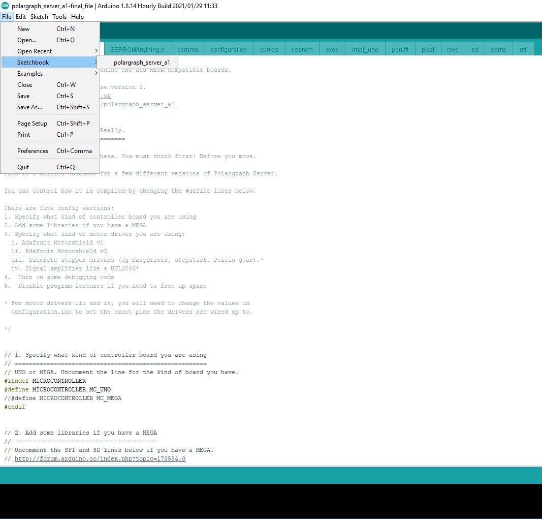
- Find the source code to use for the Arduino. (Open the cource code in the Polargraph/ arduino-source/ polargraph_server_a1 folder.)
- Upload the polargraph_server_a1.ino source code to the Arduino.
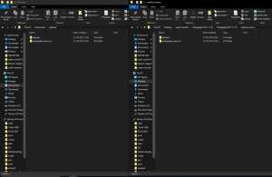
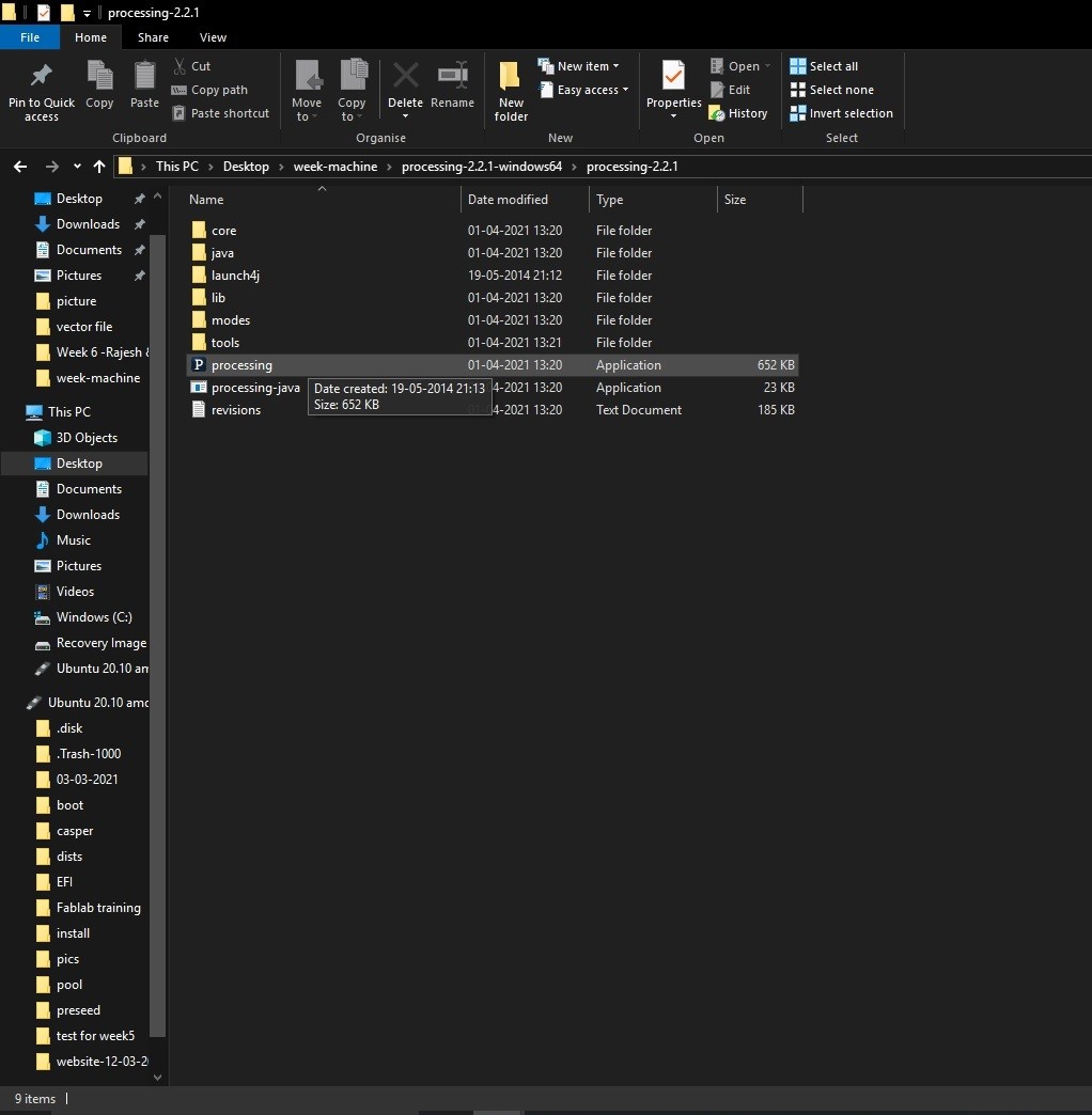
- Then open the Processing software. Find the SketchBook folder from file / preferences/ sketchbook/ location
- Find the Processing libraries in the Polargraph folder. Copy all the library folders in this folder into the libraries folder in the Processing Sketchbook folder.
- Move the Polargrapcontroller folder inside the Polargraph folder/ processing-source/ folder into the sketchbook folder.
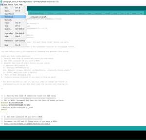
There are few important edits to be made.
polargraph_server_a1.ino
- define the microcontroller (we have an UNO)
- uncomment
#define MICROCONTROLLER MC_UNO
- Choose the stepper driver type (we use pololu)
- uncomment
#define SERIAL_STEPPER_DRIVERS
- Disable unused features (optional)
- define serial speed (57600 bps by default)
- servo pin (we used default PIN9)
const byte PEN_HEIGHT_SERVO_PIN = 9;
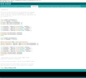
configuration.ino
- step and direction pins for the controller
#ifdef SERIAL_STEPPER_DRIVERS

#define MOTOR_A_ENABLE_PIN 8
#define MOTOR_A_STEP_PIN 2
#define MOTOR_A_DIR_PIN 5

#define MOTOR_B_ENABLE_PIN 8
#define MOTOR_B_STEP_PIN 3
#define MOTOR_B_DIR_PIN 6
AccelStepper motorA(1,MOTOR_A_STEP_PIN, MOTOR_A_DIR_PIN);
AccelStepper motorB(1,MOTOR_B_STEP_PIN, MOTOR_B_DIR_PIN);
#endif
Processing 2.2 and configuration
Processing is a flexible software sketchbook and a language for learning how to code within the context of the visual arts. Since 2001, Processing has promoted software literacy within the visual arts and visual literacy within technology. There are tens of thousands of students, artists, designers, researchers, and hobbyists who use Processing for learning and prototyping.
There is an
UI for this machine and the application can be found inside the zip. The app is written an compiled using processing 2.2.1.
It does not work in version 3+.
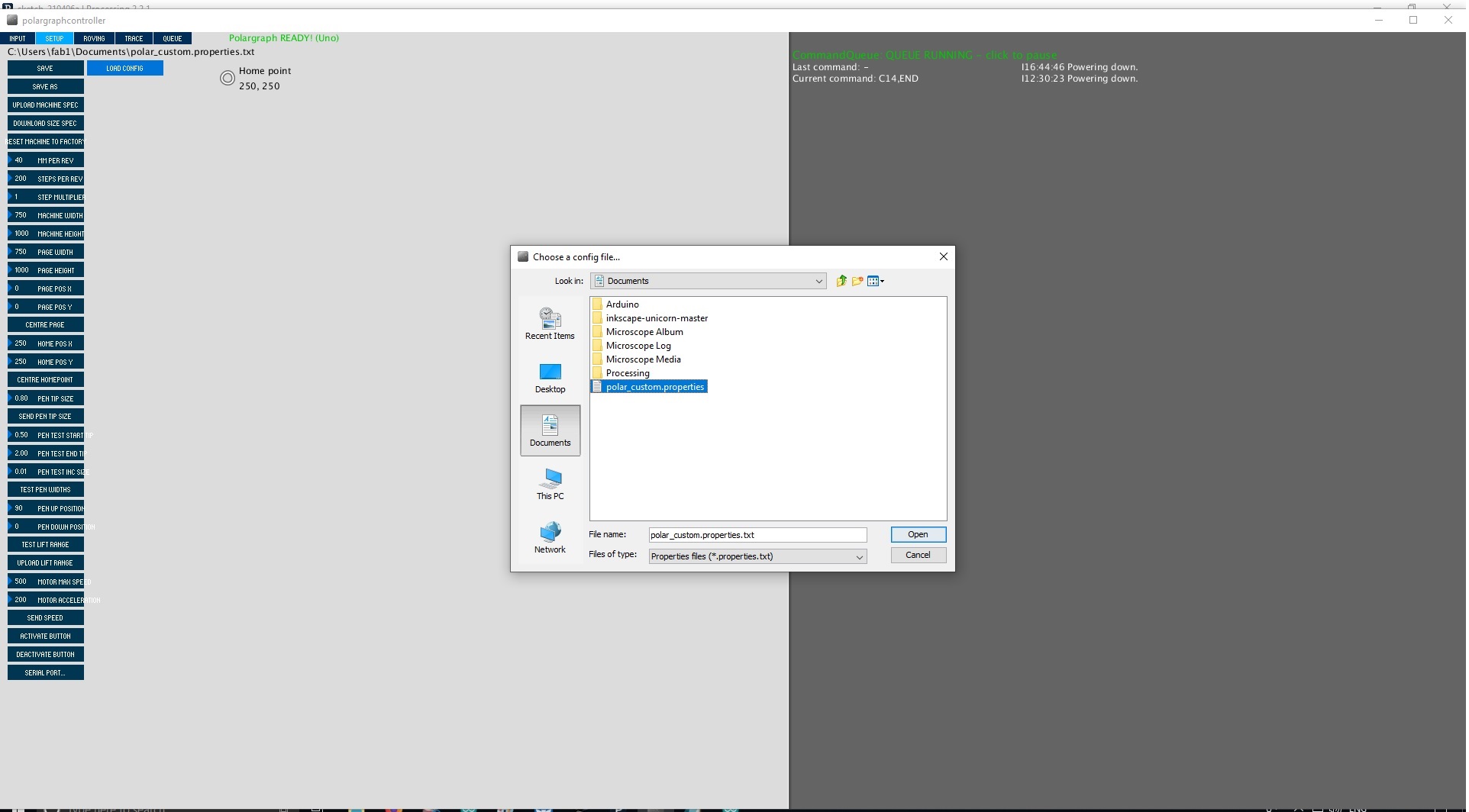
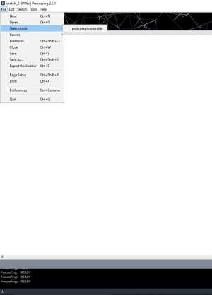
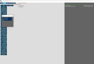
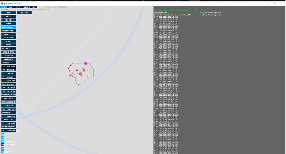
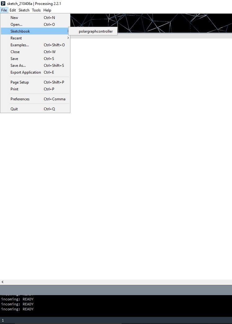
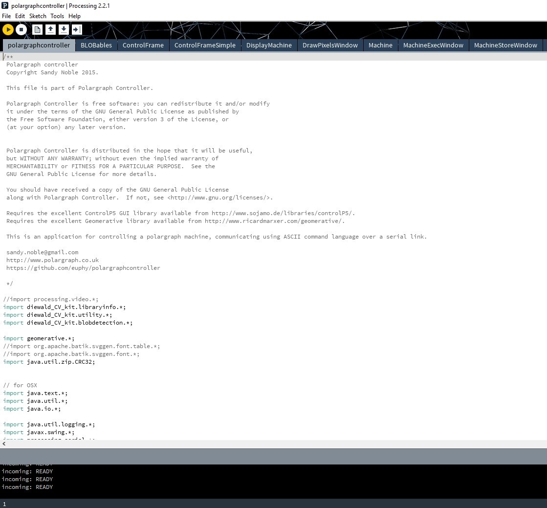
Open Processing. Then open polargraphcontroller (file -> sketchbook -> polargraphcontroller)
R
un the program by pressing the Run button.
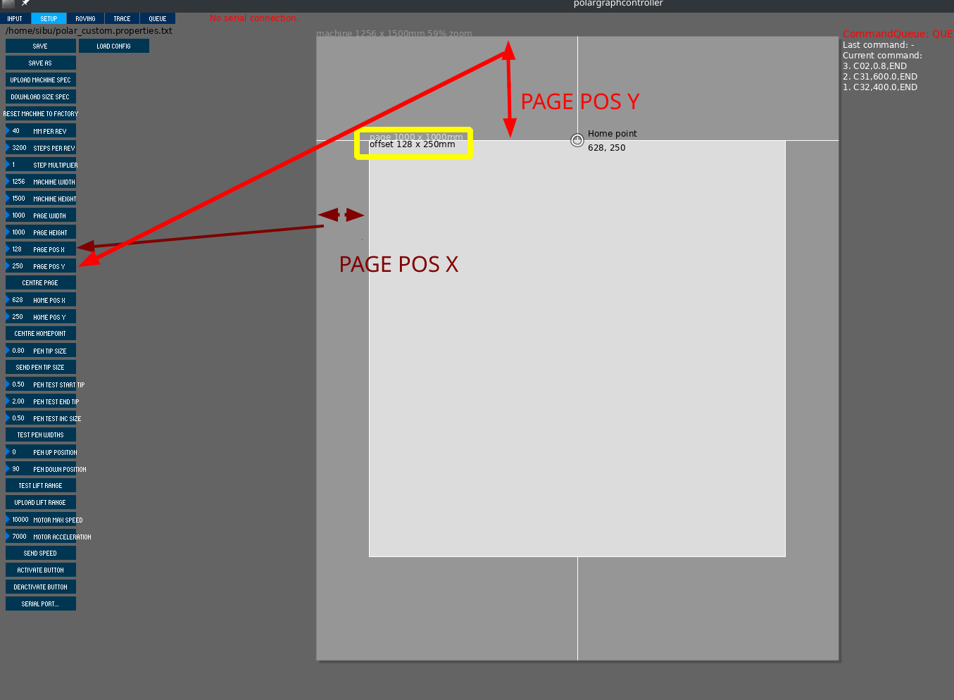
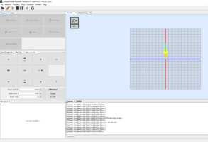
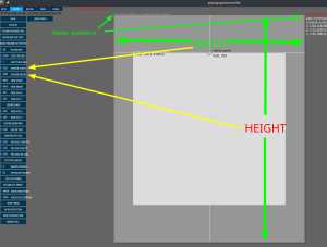
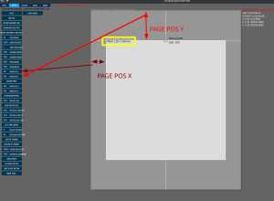
Enter the Setup section from the tool bar.
Adjust the size between two pulleys on the Machine Width
Adjust
the Machine Height (height between the pulleyand the end of the panel)
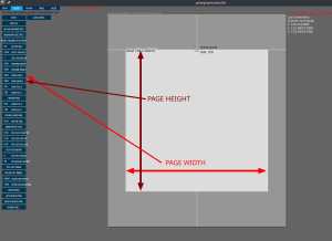
After machine dimensions, adjust the size the area you will draw.
download
click on run .
connect the com port here is com 8
i use customised file then upload
- Stepper motor and pulley settings
- Set the MM Per Rev value according to the pulley and belt you are using. For example, if the belt is GT2 the lue is 2mm. If the pulley has 16 teeth, 2x16 = 32mm. So, the belt will advance 2mm each turn.
- Adjust Steps Per Rev according to the stepper motor type. For example, if te step angle of the used stepper motor is 1.8 degrees the value is 200 steps. This value is adjust to 400 because dual motor is used.
-
Servo motor (Pen) settings
- Pen Up Position and Pen Down Position values are the operating angle of the servo motor.
- Click Serial Port and select Arduino's port from the list of connected devices.
- When the correct port is selected, the 'No Serial Connection' display will turn GREEN and the port number to which it is CONNECTED will be displayed.
- Click on 'Command Queue' and command transmission is activated.
- Click Upload Lift Range, then click Test Lift Range and test the servo motor angl
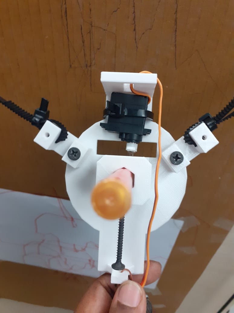
3D design and parts
Initially i was using card board leaser cut pen holder it not properly balance Presently i am using Gondola which has been downloaded.
For better improvement and precision Gondola needs to be designing and putting bearing with the belt.

final test
Reference
- https://www.youtube.com/watch?v=0qwrnUeSpYQ
- https://blog.protoneer.co.nz/arduino-cnc-shield-v3-00-assembly-guide/
- https://www.zyltech.com/arduino-cnc-shield-instructions/
- https://arduinoboardproject.com/en/how-to-install-grbl-on-arduino-uno-with-the-arduino-ide-software/
- https://github.com/grbl/grbl/archive/master.zip
- https://www.zyltech.com/arduino-cnc-shield-instructions/


Extract on the desktop the grbl-master folder, you find it in the file master.zip
Run the Arduino IDE, currently I’m using version 1.8.1
From the application bar menu, choose: Sketch -> #include Library -> Add Library from file.ZIP…
Select the folder grbl that you can find inside the grlb-master folder and click on Open
The library now is installed and the IDE software will show you this message: The library is added to your library. Check the “libraries ” menu.
Now that you have installed the GLBR library on the IDE, you must compile and install the sketch GRBL UPLOAD in the Arduino board.


polargraph_server_a1.ino
- define the microcontroller (we have an UNO)
- uncomment
#define MICROCONTROLLER MC_UNO
- uncomment
- Choose the stepper driver type (we use pololu)
- uncomment
#define SERIAL_STEPPER_DRIVERS
- uncomment
- Disable unused features (optional)
- define serial speed (57600 bps by default)
- servo pin (we used default PIN9)
const byte PEN_HEIGHT_SERVO_PIN = 9;
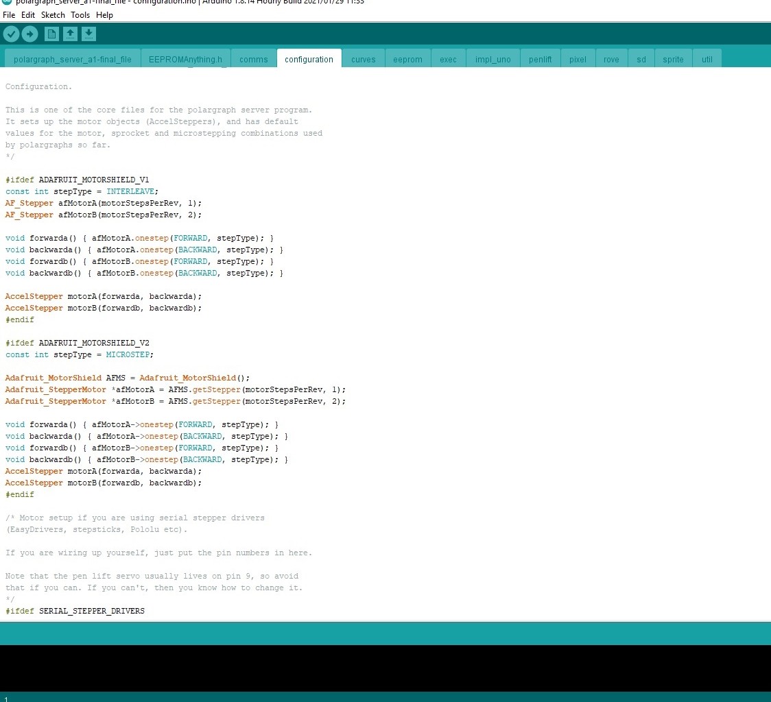
configuration.ino
- step and direction pins for the controller
#ifdef SERIAL_STEPPER_DRIVERS #define MOTOR_A_ENABLE_PIN 8 #define MOTOR_A_STEP_PIN 2 #define MOTOR_A_DIR_PIN 5 #define MOTOR_B_ENABLE_PIN 8 #define MOTOR_B_STEP_PIN 3 #define MOTOR_B_DIR_PIN 6 AccelStepper motorA(1,MOTOR_A_STEP_PIN, MOTOR_A_DIR_PIN); AccelStepper motorB(1,MOTOR_B_STEP_PIN, MOTOR_B_DIR_PIN); #endif

Open Processing. Then open polargraphcontroller (file -> sketchbook -> polargraphcontroller)
R un the program by pressing the Run button.
Enter the Setup section from the tool bar.
Adjust the size between two pulleys on the Machine Width
Adjust the Machine Height (height between the pulleyand the end of the panel)
After machine dimensions, adjust the size the area you will draw.

- Set the MM Per Rev value according to the pulley and belt you are using. For example, if the belt is GT2 the lue is 2mm. If the pulley has 16 teeth, 2x16 = 32mm. So, the belt will advance 2mm each turn.
- Adjust Steps Per Rev according to the stepper motor type. For example, if te step angle of the used stepper motor is 1.8 degrees the value is 200 steps. This value is adjust to 400 because dual motor is used.
Servo motor (Pen) settings
- Pen Up Position and Pen Down Position values are the operating angle of the servo motor.
- Click Serial Port and select Arduino's port from the list of connected devices.
- When the correct port is selected, the 'No Serial Connection' display will turn GREEN and the port number to which it is CONNECTED will be displayed.
- Click on 'Command Queue' and command transmission is activated.
- Click Upload Lift Range, then click Test Lift Range and test the servo motor angl