Output Devices:-
This week I had to work on the output devices.This week assignment was to study about the output devices and attach it to the board whih you have made earlier.
In our Fablab there are somany output devices like LED,RGB LED,LCD Display,Speaker , DC Motor , Servo Motor, BLDC (Brushless DC Motor) and Stepper motor.
Till now we all knopw about the LED,RGB LED,Speaker.I will discuss abot the motors:-
1) D C Motor.
An electric motor is an electrical machine which converts electrical energy into mechanical energy. The basic working principle of a DC motor is: "whenever a current carrying conductor is placed in a magnetic field, it experiences a mechanical force". The direction of this force is given by Fleming's left-hand rule and its magnitude is given by F = BIL. Where, B = magnetic flux density, I = current and L = length of the conductor within the magnetic field.
_50_degree_split_ring.gif)
Above animation helps in understanding the working principle of a DC motor. When armature windings are connected to a DC supply, an electric current sets up in the winding. Magnetic field may be provided by field winding (electromagnetism) or by using permanent magnets. In this case, current carrying armature conductors experience a force due to the magnetic field, according to the principle stated above.
Commutator is made segmented to achieve unidirectional torque. Otherwise, the direction of force would have reversed every time when the direction of movement of conductor is reversed in the magnetic field. This is how a DC motor works! (Animation credit: Lookang)
2)Servo Motor
A servo motor is an electromechanical device that produces torque and velocity based on the supplied current and voltage.
A servo motor works as part of a closed loop system providing torque and velocity as commanded from a servo controller
utilizing a feedback device to close the loop. The feedback device supplies information such as current, velocity, or 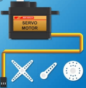
position to the servo controller, which adjusts the motor action depending on the commanded parameters.
A servo motor is part of a servo mechanism consisting of three key elements – a motor, a feedback device, and control
electronics. The motor can be AC or DC, brushed or brushless, rotary or linear, and of any size. A servomotor is a rotary
actuator or linear actuator that allows for precise control of angular or linear position, velocity and acceleration. It consists
of a suitable motor coupled to a sensor for position
3)BLDC Motor:-
With a BLDC motor, it is the permanent magnet that rotates; rotation is achieved by changing the direction of the magnetic fields generated by the surrounding stationary coils. To control the rotation, you adjust the magnitude and direction of the current into these coils
The simplest type of motor is the brushed DC motor. In this type of motor, electrical current is passed through coils that are arranged within a fixed magnetic field. The current generates magnetic fields in the coils; this causes the coil assembly to rotate, as each coil is pushed away from the like pole and pulled toward the unlike pole of the fixed field. To maintain rotation, it is necessary to continually reverse the current—so that coil polarities will continually flip, causing the coils to continue “chasing” the unlike fixed poles. Power to the coils is supplied through fixed conductive brushes that make contact with a rotating commutator; it is the rotation of the commutator that causes the reversal of the current through the coils. The commutator and brushes are the key components distinguishing the brushed DC motor from other motor types. Figure 1 illustrates the general principle of the brushed motor.(Credit:-https://www.renesas.com)
4)Stepper Motor:-
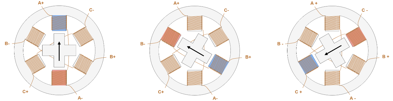
A stepper motor is an electric motor whose main feature is that its shaft rotates by performing steps, that is, by moving by a fixed amount of degrees. This feature is obtained thanks to the internal structure of the motor, and allows to know the exact angular position of the shaft by simply counting how may steps have been performed, with no need for a sensor. This feature also makes it fit for a wide range of applications.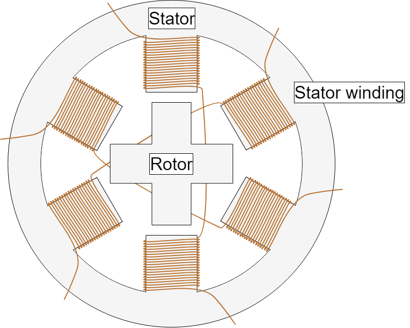
The basic working principle of the stepper motor is the following: By energizing one or more of the stator phases, a magnetic field is generated by the current flowing in the coil and the rotor aligns with this field. By supplying different phases in sequence, the rotor can be rotated by a specific amount to reach the desired final position. Figure 2 shows a representation of the working principle. At the beginning, coil A is energized and the rotor is aligned with the magnetic field it produces. When coil B is energized, the rotor rotates clockwise by 60° to align with the new magnetic field. The same happens when coil C is energized. In the pictures, the colors of the stator teeth indicate the direction of the magnetic field generated by the stator winding.(Credit:-https://www.monolithicpower.com)
I decided to use LCD as an output device.In our lab we are having Lumex -LCMs01602dtr/M 16x2 LCD Module.I decided to first try it with the Ardiuno Board.
Thsi week i tried to understand the operation of LCD Display with Arduino Board and programming the arduino to display the harcters on the LCD Display.
The PIN configuration of the Lumex -LCMs01602dtr/M 16x2 LCD Module is
| PIN No | Symbol | Function |
| 1 | Vss | GND(0 V) |
| 2 | Vd0 | 5 V |
| 3 | Vd | For LCD Drive |
| 4 | RS | Register Select Signal |
| 5 | R/w | Data Read Write |
| 6 | E | Enable |
| 7-14 | DB0-DB7 | Data Bus Selectable 4 or 8 Bit Mode |
| 15 | NC | No Connection |
| 16 | NC | No Connection |
Making Connection to the Arduino Board with LCD Display
Connect the following pins otf LCD Display to th Coresponding Pins of the Arduino.
| LCD Module Pins | Arduino Pins |
| 1 | Gnd |
| 2 | Vcc |
| 3 | Variable Potentiometer (For Contrast) |
| 4 | 2 |
| 5 | |
| 6 | 3 |
| 7 | - |
| 8 | - |
| 9 | - |
| 10 | - |
| 11 | 4 |
| 12 | 5 |
| 13 | 6 |
| 14 | 7 |
| 15 | Vcc (backlight) |
| 16 | Gnd(Backlight) |
This is our LCD Screen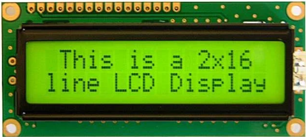
For Conneting the LCD screen to the arduino first i had to solder the Conn heare of 16 pins.We can attach either male or female header as required.
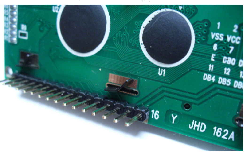
Like As Shown connect the pi headers.
About the LCD Dislpay Pinout
The parallel interface consists of the following pins:-
>Power Supply pins (Vss/Vcc): Power the LCD
>Contrast pin (Vo): Control the display contrast
>Register Select (RS) pin: Controls where in the LCD's memory you're writing data to
>Read/Write (R/W): Selects reading mode or writing mode
>Enable pin: Enables writing to the registers
>8 data pins (D0 -D7): The states of these pins (high or low) are the bits that you're writing to a register when you write, or the values you're reading when you read.
>Backlight (Bklt+ and BKlt-) pins: Turn on/off the LED backlight
The Hitachi-compatible LCDs can be controlled in two modes: 4-bit or 8-bit. The 4-bit mode requires seven I/O pins from the Arduino, while the 8-bit mode requires 11 pins.
For displaying text on the screen, you can do most everything in 4-bit mode
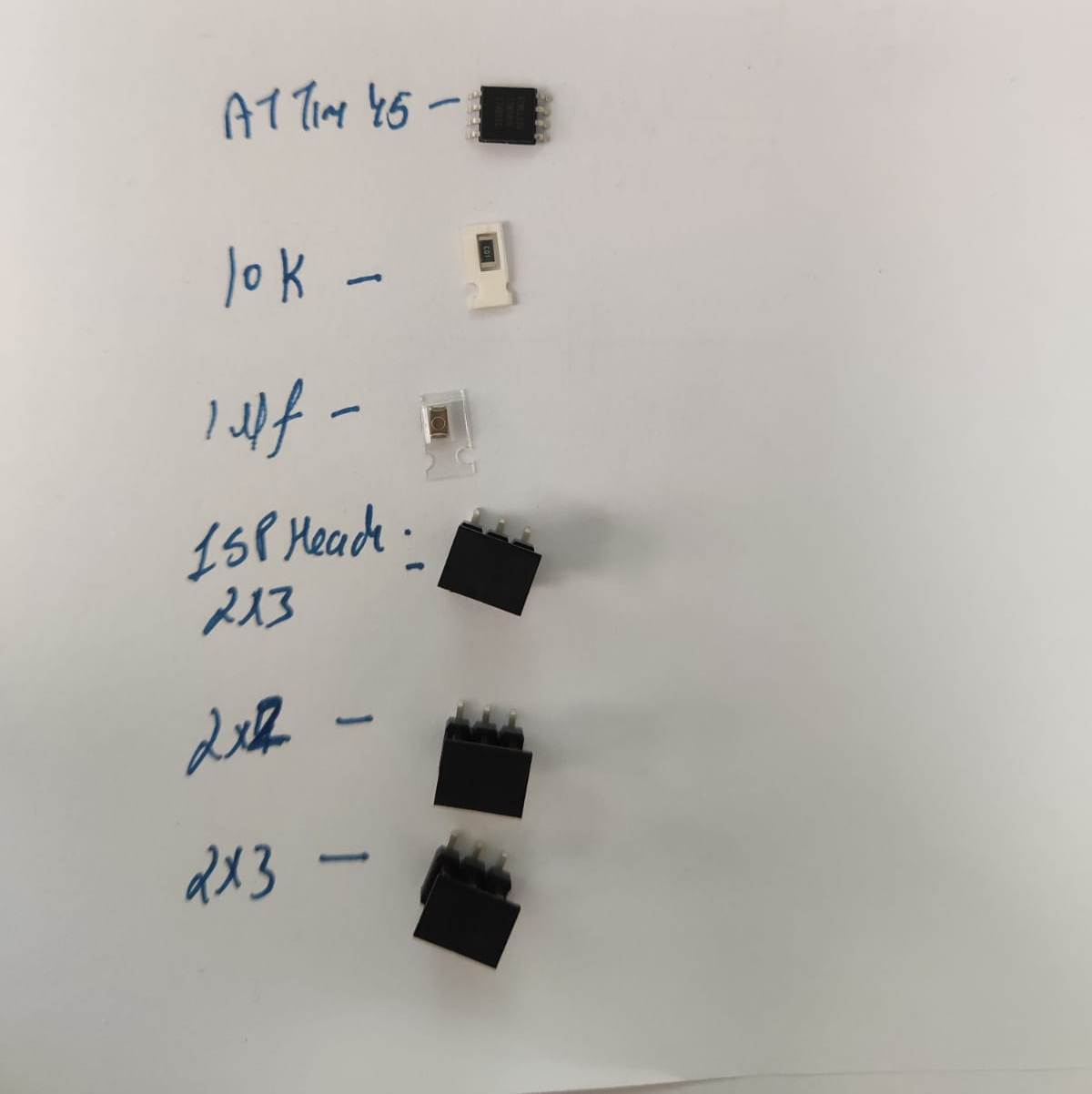
For connectiong the LCD we need the following items 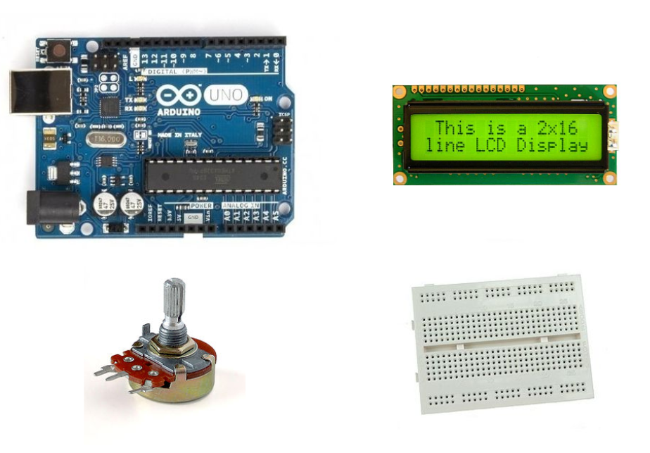
One Ardiuno Board
One Bread Board
Jumper Wires
LCD screen
Potentiometer.
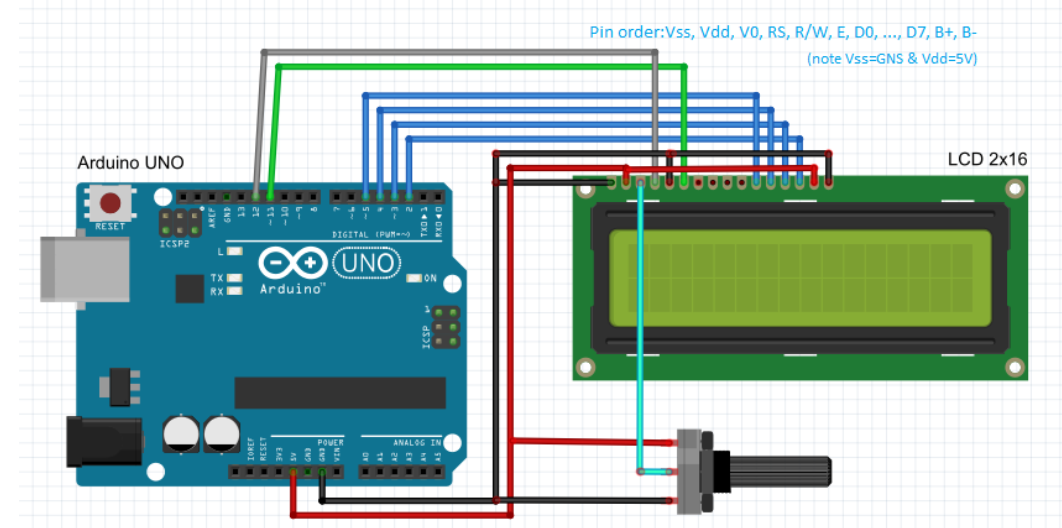
This is our circuit how we had to connect the ardiuno board to lcd screen and potetio meter using bread board.
Here is the image of the excercise 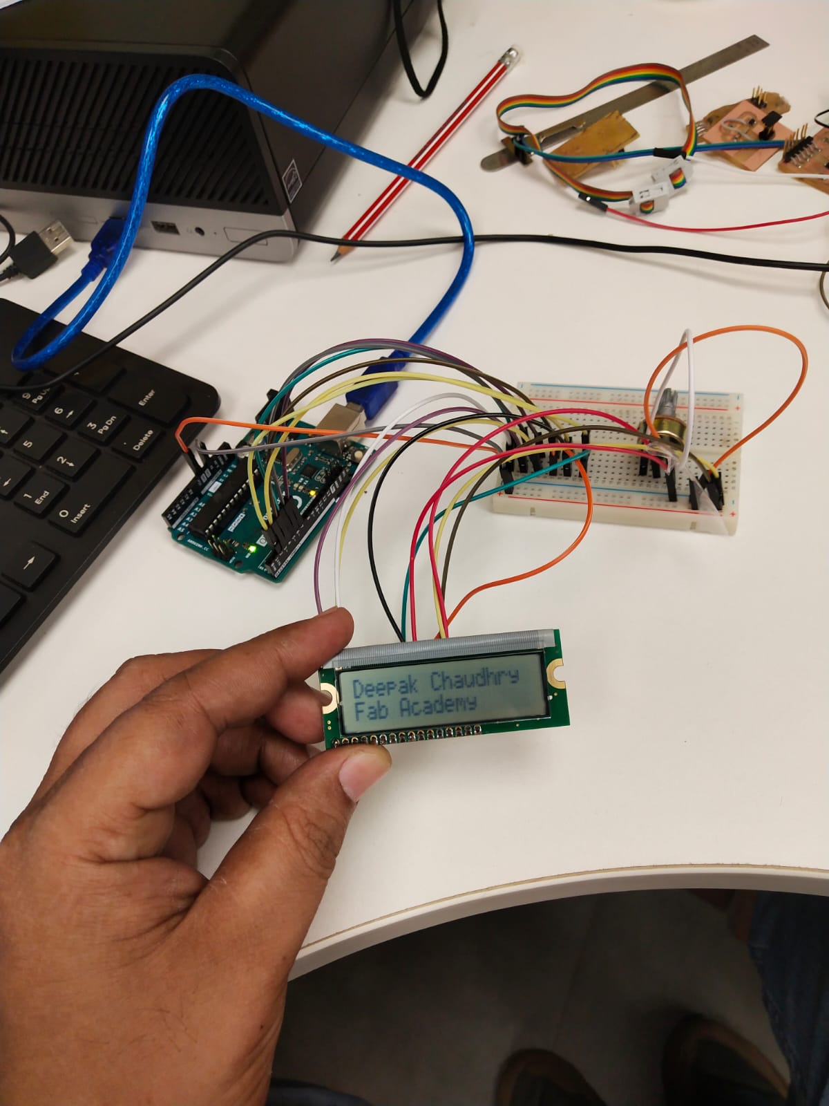
After opening of the fab lab after covid i decided to make to run the survo motor with the Attiny 44 Micro controller.
I reffred to the Board Made by Neil for doing this.
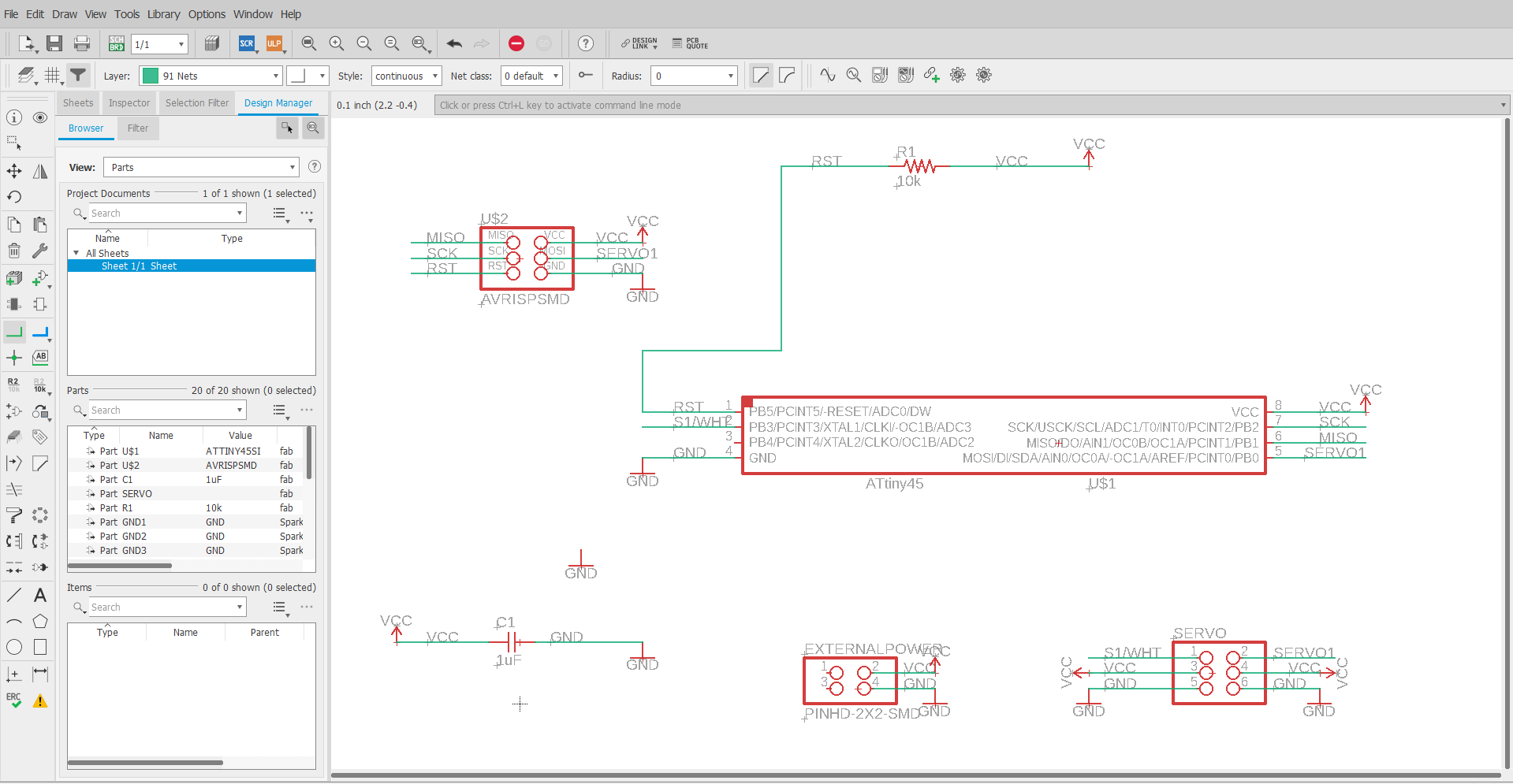
I designed the board using the Eagle
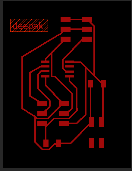
I Milled the board using the design rules in the electronics production week and soldered thw board
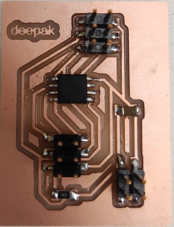
Now it was the time to programm the board
Here is the video of the excercise
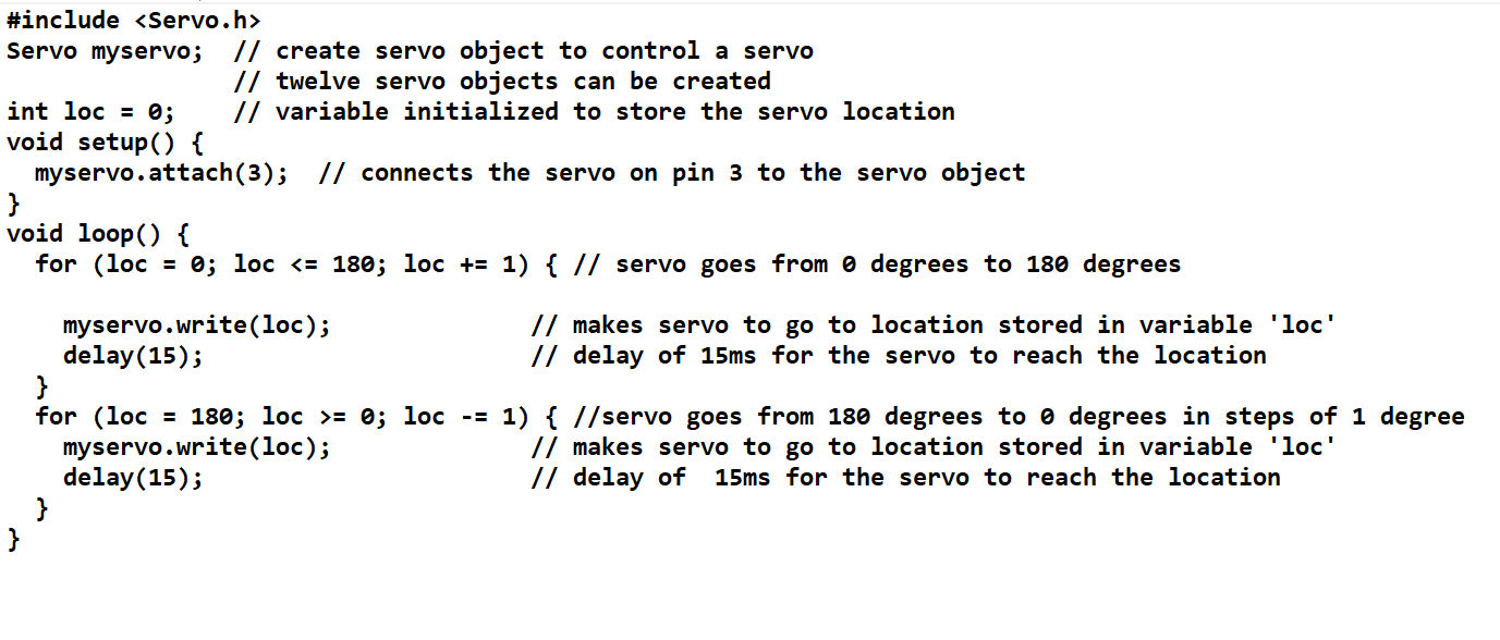
Attaching the servo to the ATTiny 45 we can use the servo library of the of the ardiuno.
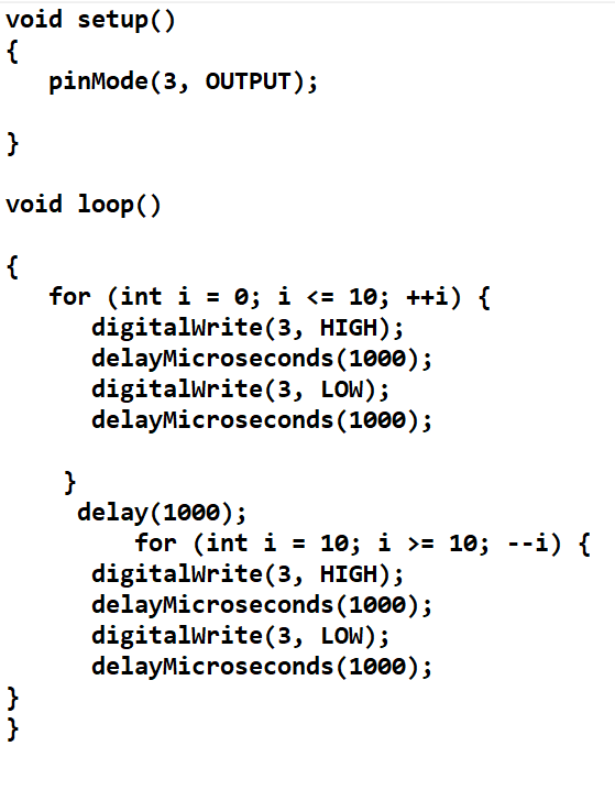
digitalWrite()
The digital pins have only two modes – ON (1) or OFF (0).It will be either high or eithery low as it is a digital funcion.It works according to the binary language."0" or "1". 0 means it will be OFF or Zero and 1 means ON or 5V.Digital pin always gives the output of 5V when HIGH and 0V when LOW.
digitalWrite(pin,value) // sets ‘pin’ to value (LOW or HIGH)
Example: blinking LED
int led = 13;
void setup() {
pinMode(led, OUTPUT); // digital pin as an output
}
void loop() {
digitalWrite(led, HIGH); // turn the LED on
delay(1000); // wait for a second
digitalWrite(led, LOW); // turn the LED off by making the voltage LOW
delay(1000); // wait for a second
}
analogWrite()
The value of 0 gives 0 volts output at the specified pin; a value of 255 generates 5 volts output at pin. Values between 0 and 255, the pin value goes between 0 and 5 volts.. For example, a value of 64 will be 0 volts for three-quarters of the time, and 5 volts for one quarter of the time; a value of 128 will be at 0 volts half the time and 5 volts half of the time; and a value of 192 will be 0 volts one quarter of the time and 5 volts three-quarters of the time.analogWrite(255) requests a 100% duty cycle (always on), and analogWrite(127) is a 50% duty cycle (on half the time).
Duty Cycles = (High Period/Total Period ) x 100
Understanding the working of the analogWrite() funcion using the fading LED example.
Fading LED
void setup() {
pinMode(3, OUTPUT); //initialize digital pin 3 as an output.
}
void loop() // the loop function runs over and over again forever
{
while(intensity != 0) // loop for decrementing the intensity
{
analogWrite(3, intensity);
delay(d);
intensity = intensity - 1;
}
while((intensity < 255) && (intensity >= 0)) //loop for incrementing theintensity
{
analogWrite(3, intensity);
delay(d);
intensity = intensity + 1;
}
}
The over all difference between analogWrite() and digitalWrite() is that in analogWrite finction the volatage level can be quantised between 0-255 values i.e(0-5 volts) but in digitalWrite function the volatge level can only be either 0v or 5 volts.AnalogWrite is used for PWM pins and digitalWrite is used for ddigital Pins