Networking And Communications :-
This week I had to design, build, and connect wired or wireless node(s) with network or bus addresses
First we will learn about the Communication protocols in the Embedded Systems:-
Communication Protocols in Embedded Systems.
Embedded System is an electronic system or device which employs both hardware and software. A processor or controller takes input from the physical world peripherals like sensors, actuators etc., processes the same through appropriate software and provides the desired output.
In this case, the components have to communicate with each other to provide the anticipated output. Each communicating entity should agree to some protocol to exchange information. Many different protocols are available for embedded systems and are deployed depending upon the application area.In general, the communication protocols is associated with physical layer describing the signals incorporated, signal strength, hand shaking mechanism, bus arbitration, device addressing, wired or wireless, data lines etc. The processes such as system configuration, selection of baud rate and transmitting & receiving data is associated with application layer.
Types of Communication Protocols in Embedded Systems:-
Communication protocols are broadly classified into two types:
a)Inter System Protocol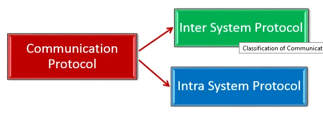
b)Intra System Protocol
Inter System Communication Protocols
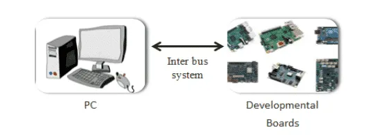
Inter system protocols establish communication between two communicating devices i.e. between PC and microprocessor kit, developmental boards, etc. In this case, the communication is achieved through inter bus system.
Types of Inter System Communication Protocols
- USB Communication protocols
- UART Communication protocols
- USART Communication protocols
USB Communication Protocols
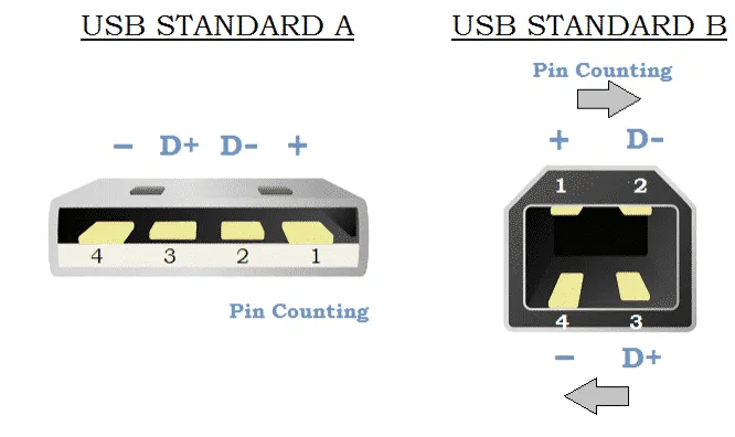
Universal Serial Bus (USB) is a two-wired serial communication protocol. It allows 127 devices to be connected at any given time. USB supports plug & play functionality.
USB protocol sends and receives the data serially between host and external peripheral devices through data signal lines D+ and D-. Apart from two data lines, USB has VCC and Ground signals to power up the device. The USB pin out is shown in Adjacent image.
 .
.
Data is transmitted in the form of packets where two devices communicate each other. Data packets compose of 8 bits (byte) with LSB (Least Significant Bit) transmitted first.
USB associates NRZI (Non Return to Zero Invert) encoding scheme to transmit data with sync field to synchronize the host system and receiver clock signals.
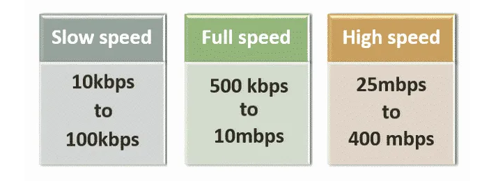
In USB, data is transferred in three different speeds such as in image beside:
Advantages of USB Communication Protocol
The advantages of USB Communication Protocol are as follows:
- Fast and simple.
- It is of low cost.
- Plug and Play hardware.
Disadvantages of USB Communication Protocol
The disadvantages of USB Communication Protocol are as follows:
- Needs powerful master device.
- Specific drivers are required.
UART Communication Protocols
Universal Asynchronous Receiver/Transmitter (UART) is not a communication protocol but just a physical piece of hardware which converts parallel data into serial data. Its main purpose is to transmit and receive data serially.
UART is also two-wired i.e., the serial data is handled by Tx (Transmitter) and Rx (Receiver) pins.
UART transmits data asynchronously, which induces that no clock signal is associated in transmitting and receiving data. Instead of clock signal, UART embed start and stop bits with actual data bits, which defines the start and end of data packet.
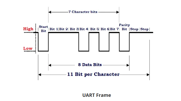
When receiver end detects the start bit, it starts to read the data bits at specific baud rate meaning both transmitting and receiving peripherals should work under same baud rate. UART works under half duplex communication mode meaning it either transmits or receives at a time.
Example: Emails, SMS
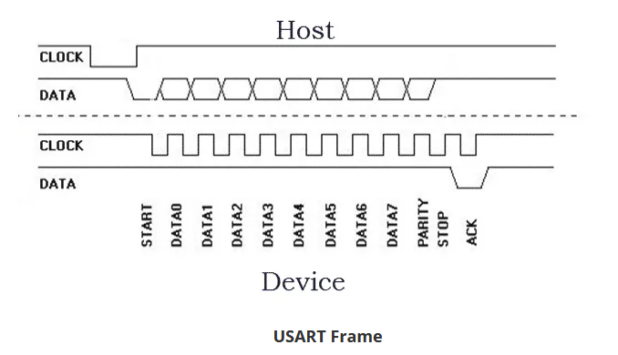
USART Communication Protocol
Universal Synchronous Asynchronous Receiver/Transmitter (USART) is identical to that of UART with only added functionality synchronous. That is, the transmitter will generate a clock signal which will be recovered at the receiver end from the data stream transmitted without knowing baud rate ahead.
UART works under full duplex communication mode meaning it can transmit and receive data at same time.
USART encompass the abilities of UART, which enables application of both depending on the applications area.
Example: Telecommunications
The advantages of UART/ USART Communication Protocol are as follows:
- Clock signal is not required
- Cost effective
- Uses parity bit for error detection
- Requires only 2 wires for data communication
Disadvantages of UART/ USART Communication Protocol
The disadvantages of UART/ USART Communication Protocol are as follows:
- Doesn’t support multiple master client functionality
- Baud rate of communicating UART should be within 10 percent of each other
Intra System Communication Protocols
The Intra system protocol establishes communication between components within the circuit board. In embedded systems, intra system protocol increases the number of components connected to the controller.
Increase in components lead to circuit complexity and increase in power consumption. Intra system protocol promises secure access of data from the peripherals.
Types of Intra System Communication Protocols
Intra system protocol can be categorized into:
- I2C Protocol
- SPI Protocol
- CAN Protocol
I2C Communication Protocols
Inter Integrated Circuit (I2C) is a serial communication protocol developed by Philips Semiconductors. The main purpose of this protocol is to provide easiness to connect peripheral chips with microcontroller. In embedded systems, all peripheral devices are connected as memory mapped devices to the microcontroller.
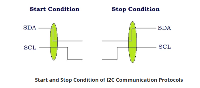
I2C necessitates two wires SDA (Serial Data Line) and SCL (Serial Clock Line) to carry information between devices. These two active wires are said to be bidirectional.
I2C protocol is a master to client communication protocol. Each client is been provided with unique address. In order to establish communication, master device initially sends the target client address along with R/W (Read/Write) flag. The corresponding client device will move into active mode leaving other devices in off state.
Once the client device is ready, communication starts between master and client devices. One bit acknowledgment is replied by the receiver if transmitter transmits 1 byte (8 bits) of data. A stop condition is issued at the end of communication between devices.
I2C is a serial protocol used on a low-speed 2-wire interface. It was originally developed by Phillips in 1982 to allow integrated circuits within television receivers to communicate with one another.
Times have changed, Phillips is now NXP and I2C has become a communication standard that is supported by virtually every major semiconductor manufacturer.
I2C is an abbreviation for “Inter-Integrated Circuit”. It is also called “IIC” or ‘I squared C”.
Uses and Limitations
I2C is used with microcontrollers like the Arduino and with microcomputers like the Raspberry Pi. Many displays and sensors interface to their host controller using I2C.
I2C does have several limitations however. It is not particularly fast, although for most of its intended uses it is plenty fast enough.
I2C can only be used over short distances, after all, it was originally meant to communicate between integrated circuits on the same printed circuit board. The maximum distance of reliable transmission decreases as the speed increases, at the slowest speed (100 Kbaud or a clock rate of 100 KHz) the maximum distance is about a metre.
I2C Speeds
The original I2C bus had a maximum speed of 100 KHz. Most common applications still use this speed, as it is quite sufficient for transferring data from sensors and to simple displays.
I2C and has some higher speed modes. Not all I2C devices support these modes:
- Fast Mode – This has a maximum clock speed of 400 KHz.
- Hi-Speed Mode – A maximum clock frequency fo 3.4 MHz
- Ultra Fast Mode – Maximum clock frequency of 5 MHz
How I2C Works
An I2C bus has two signals, along with a power and ground connection.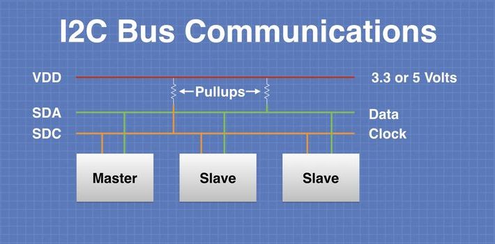
The two signal lines are as follows:
- SDA – This is the bidirectional data line.
- SCL – This is the clock signal.
There are two pull-up resistors attached to each signal line, they pull the bus up to the supply voltage when it is inactive.
Note that the supply voltage is not standard, it can be either 3.3 or 5-volts. It can also be a lower voltage for some high-speed I2C implementations.
This difference in supply voltages can cause issues when you are interfacing I2C devices that use different logic levels. We will discuss this more in a future article when I show you how to interface a Raspberry Pi (3.3-volt logic) with an Arduino Uno (5-volt logic).
There are two types of devices that can be interfaced to the I2C bus – Masters and clients.
The Master device controls the bus and supplies the clock signal. It requests data from the clients individually. There can be more than one master device on the bus but only one can be the active master at any given moment.
The master devices do not have an address assigned to them.
client devices do have an address, and this address needs to be unique on the bus. They use a 7-bit addressing scheme, so up to 128 clients can be on one I2C bus. In real life this large collection of devices is never used, it is rare to see over a dozen I2C devices on one bus.
A newer, 10-bit addressing scheme has been implemented, it is backward-compatible with the existing 7-bit addressing method.
Commercial I2C devices are allocated I2C address by NXP, who maintain the bus specifications. Although I2C has been open source since 2006 there is a fee charged for obtaining a client address from NXP. No fee is required for master devices, or for devices that are not meant for commercial manufacture.
Some I2C devices are assigned multiple addresses, usually variances in the lower address bits. These devices can be manually configured for different addresses, allowing multiple devices of the same type to be used on a single I2C bus.
Advantages of I2C Communication Protocols
The advantages of I2C Communication Protocols are as follows:
- Provides good communication between onboard devices which are accessed infrequently
- Addressing mechanism eases master client communication
- Cost and circuit complexity does not end up on number of devices
Disadvantages of I2C Communication Protocols
The biggest disadvantage of I2C Communication Protocols is its limited speed.
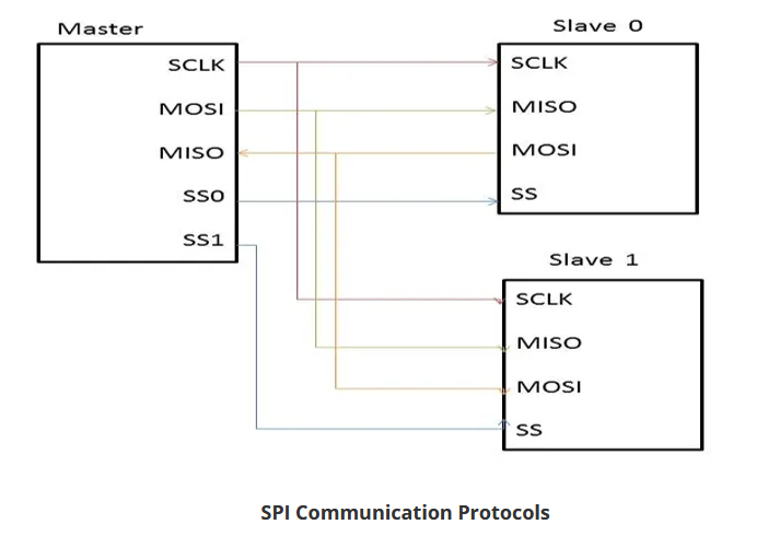
Serial Peripheral Interface (SPI) Communication Protocols
SPI (Serial Peripheral Interface) is one of the serial communication protocol developed by Motorola. It is a 4-wire protocol namely MOSI (Master Out Slave In), MISO (Master In Slave Out, SS (Slave Select), and SCLK (Serial Clock).
As I2C protocol, SPI is also a master to client communication protocol. In SPI, the master device first configures the clock at a particular frequency. Furthermore the SS line is used to select the appropriate client by pulling the SS line low where it is normally held high.
The communication is established between the selected client and the master device as soon as appropriate client device is selected.
SPI is a full duplex communication protocol. SPI doesn’t limit data transfer to 8 bit words.
Advantages of SPI Communication Protocols
The advantages of SPI Communication Protocol are as follows:
- Faster than asynchronous serial communication protocol.
- Support multiple clients connectivity.
- Universally accepted protocol and low cost.
Disadvantages of SPI Communication Protocol
The disadvantages of SPI Communication Protocol are as follows:
- Requires more wires than other communication protocols.
- Master device should control all client communications (client-client communication is impossible).
- Numerous client devices leads to circuit complexity.
Controller Area Network (CAN) Communication Protocol
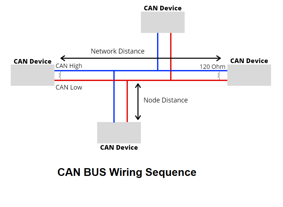
CAN (Controller Area Network) is a serial communication protocol developed by the Robert Bosch for intra vehicular communication. It requires two wires CAN High (H+) and CAN low (H-) for data transmission. CAN protocol is based on a message oriented communication protocol. With the CAN protocol, a single wire connects all of the electronic systems, actuators, and sensors in the vehicle into one circuit that facilitates high-speed data transmission between all components.
What is CAN BUS?
CAN stands for Controller Area Network, it is used to allow microcontrollers and devices to communicate with each other within a vehicle without a host computer which allows for control and data acquisition. These devices are also called Electronic Control Units (ECU) and they enable communication between all parts of a vehicle.
Today, you can find up to 70 ECUs in a modern car. CAN is a serial communication bus designed for industrial and automotive applications. For example, they are found in vehicles, farming equipment, industrial environments, etc.
- The CAN BUS protocol consists of two wires (As Shown In Above Image )for bi-directional data transmission as shown above which are
- CAN_H (CAN High)
- CAN_L (CAN Low)
- The wires act as a differential line which means the CAN signal either 0 or 1, can be represented by the potential difference between the two wires
- For example, if the difference is positive and large than a certain minimum voltage = 1. If the difference is negative = 0
- For CAN termination, as you can see from the picture above, a single 120 Ohm is generally used at the 2 ends of the CAN network.
How does CAN BUS works?
The fuel level, door sensors, odometer, and many more parts of a car have to communicate with each other some how, and CAN BUS is what they used to do that. These CAN compatible components, which are called “nodes” are connected with a 3-string copper wires, with no central router to govern the flow of data. Every node can hear the messages of every other node.
Every node has an ID, where the ones with the higher priority ID can have the priority to “talk” first while the others “listen”. This is to ensure that there are never two nodes talking at the same time. The biggest benefit of CAN BUS is to be able to just connect components without having to worry about signal routing.
Why other communication protocols like UART, SPI and I2C are not use in Vehicles?
Compared to other communication protocols like UART, SPI and I2C, using CAN BUS communication protocol are much more reliable as they are standard automotive communication protocols that are used to transmit vital data like a throttle position in a vehicle. If miscommunication or loss of data occurs, it could lead to critical failures.
In a vehicle, safety and reliability are the two most valued features. CAN BUS are therefore the ideal protocols for vehicular usage.
What will happen if there is no CAN in the car?
Without CAN BUS protocol, electronic modules in vehicles will have to communicate with each other using direct, point-to-point analog signal lines. With each module requiring a direct line connected for communication, not only is it time-consuming, it will be messy with all the excessive amount of wiring as seen on the picture above. And there may be unreliable communication between devices. Excessive wires may require additional equipment, which also creates cost issues.
With CAN BUS protocol, it eliminates the need of all these wirings by enabling electronic devices to communicate with each other with a single multiplex wire that connects each node in the network to the main dashboard as seen on the picture above.
The multiplex wire and architecture enable signals to be combined and transmitted over the entire network with just a single wire while ensuring each electronic module in vehicles receives data from sensors and actuators. This allows the user to be able to connect any number of ECUs in your vehicle through the two-wire bus.
It also allows for several features to be added via just software. Furthermore, an ECU is able to use data from another ECU which eliminates the need to install the same sensors in multiple devices.
CAN BUS Protocol Speed and Range
- Communication speeds of the CAN BUS protocol ranges from 10kpbs to 1Mbps.
- The speed also depends on the length of wire used. The shorter it is, the faster the communication speed and the longer it is, the slower the communication speed.
- For example, at 40 meters, the speed will be at 1Mbps. At 1000 meters, the speed can be at 50kpbs.
- The node distance is generally advised to be no more than 0.3 meters / 1 foot.
CAN Message
- To fully understand how the CAN BUS protocol works, let us look at the frames sent over the network.
- The CAN message contains many segments. The 2 main segments, identifier and data, will be the ones transmitting the data.
- The identifier is used to identify CAN devices in a CAN network while data will be the sensor or control data that have to be sent from one device to another.
- The identifier or CAN ID is either 11 or 29 bits in length depending on the type of CAN protocol used.
- Standard CAN = 11 bit
- Extended CAN = 29 CAN
- While the data can be anywhere from 0 to 8 bytes.
Why use CAN BUS protocol?
CAN BUS protocol is widely used thanks to the following advantages:
Low Cost
- ECUs communicate via a single CAN interface compared to, for example, direct analog signal lines that reduce errors, weight, and costs.
- With its multiplex wiring that combines analog and digital signals and their transmission over a shared medium, it reduces the amount of wiring needed.
- When adding or reducing some equipment, it can be easily operated, and there is no need to carry out large-scale transformation of the system, which saves a lot of manpower.
Centralized
- As CAN BUS supports centralized control over electronic devices that are connected to the network, it allows for central error diagnosis and configuration across all ECUs
- Error handling is also built into the CAN protocol where nodes can check for errors in transmission while maintaining its own error counter. For example, the protocol supports different error detection capabilities such as bit error, ack error, form error, CRC error, etc.
Flexible
- As each CAN connected ECU can receive all transmitted messages, it can also decide whether it is relevant and act accordingly.
- The CAN BUS protocol is also a message-based communication protocol where nodes on the bus have no identifying information.
- With the above features, nodes can easily be added or remove and modified.
- For beginners, it will be easy to integrate new electronic devices into the CAN BUS network without any significant programming overhead.
Robust
- When choosing a communication protocol, durability and reliability are very important. You would want your communication protocol to be self-sustaining and durable for a long period of time without maintenance.
- With the CAN BUS, the system is robust towards electric disturbances and electromagnetic interference which makes it ideal for vehicles.
Efficient
- CAN messages frames are prioritized by ID where the top priority will get bus access and yet frames would not be interrupted.
- Due to flash programming, it also saves time together with less and simple wiring.
Advantages of CAN Communication Protocols
The advantages of CAN Communication Protocols are as follows:
- Low cost and reliable
- Shows robust performance
- Secured and fast protocol
Disadvantages of CAN Communication Protocol
The disadvantages of CAN Communication Protocol are as follows:
- Automotive oriented
- Bit complex protocol
(Credits :-https://electricalfundablog.com , https://www.seeedstudio.com)
Here I will update the implementation excercise of the CAN Bus protocol soon as soon as the lockdown is finished....)
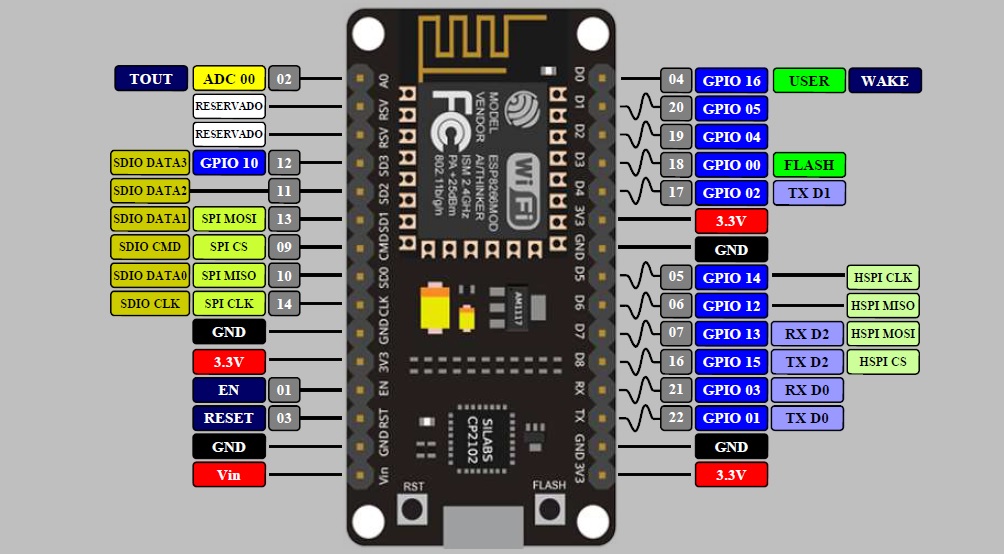
This Week I studied the datasheet of the ESP 8266 Node MCU 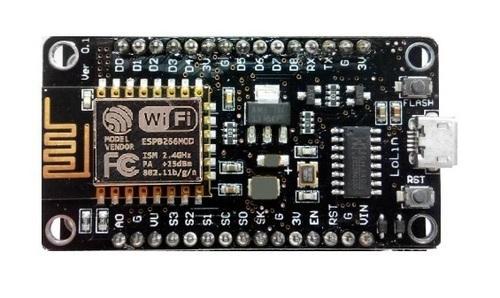
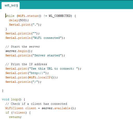
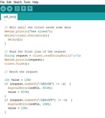
I tried to make the IoT based LED project using the ESP 8266 Node MCU.
Even by doing some small modifications in this same project, we can use this for home automation. For controlling the LED using Webserver we need to create an HTML webpage. The page will have two buttons for turning LED ON and OFF.
Components Required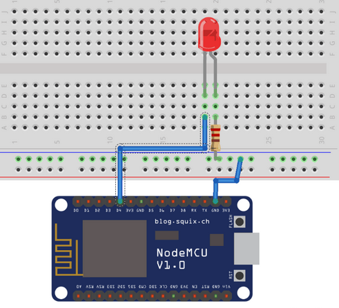
- ESP8266 NodeMCU
- LED
- 250 ohm Resistor
- Breadboard
- Jumper Wires
- D7 of NodeMCU to LED's +ve.
- G of NodeMCU to LED's -ve.
But before that we had to add NODE MCU package to the arduino IDE
For this
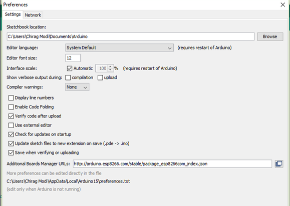
1) Open up Arduino IDE. Go to Files-> Preferences. Enter http://arduino.esp8266.com/stable/package_esp8266com_index.json into Additional Board Manager URLs field
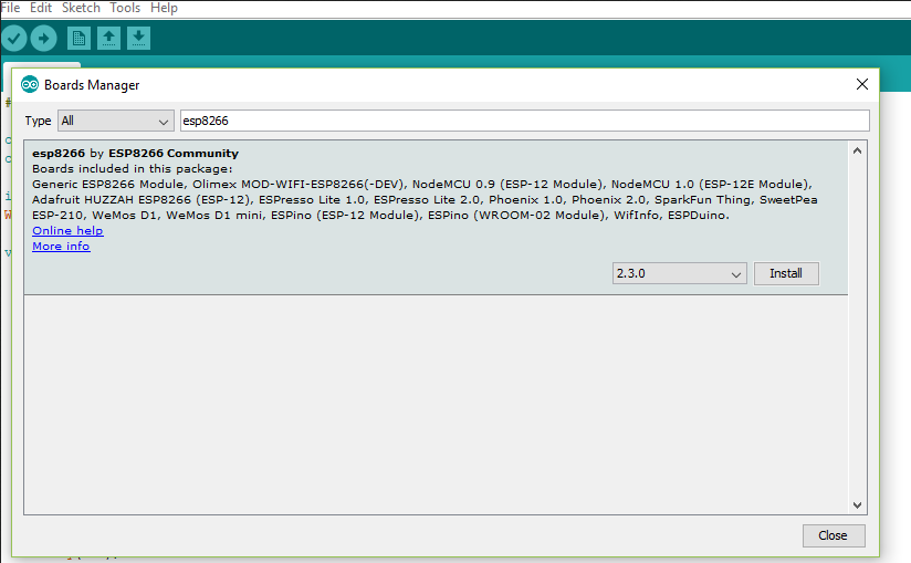
2)Now go to Tools->Boards->Board Manager, and search for ESP8266 and install the package.
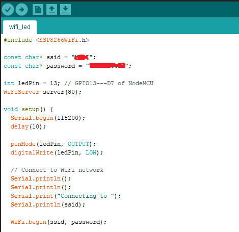
In code
change ssid to your ssid name
and Password to your SSID's password
When u have successfully built your connection on the breadboard and write coding, you have to upload the coding into the NodeMCU by using a micro USB.
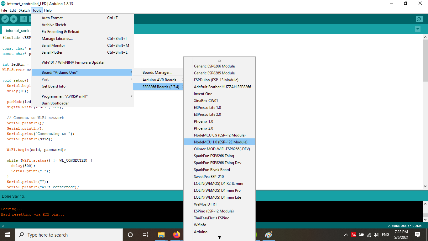
Now, go to Tools > Board > ESP8266 Modules and you can see many options for ESP8266. Select "NodeMCU 1.0 (ESP-12E Module). Next, select your port. If you cant recognize your port, go to the Control Panel > System > Device Manager > Port and update your USB driver.
Now upload the code to the board.
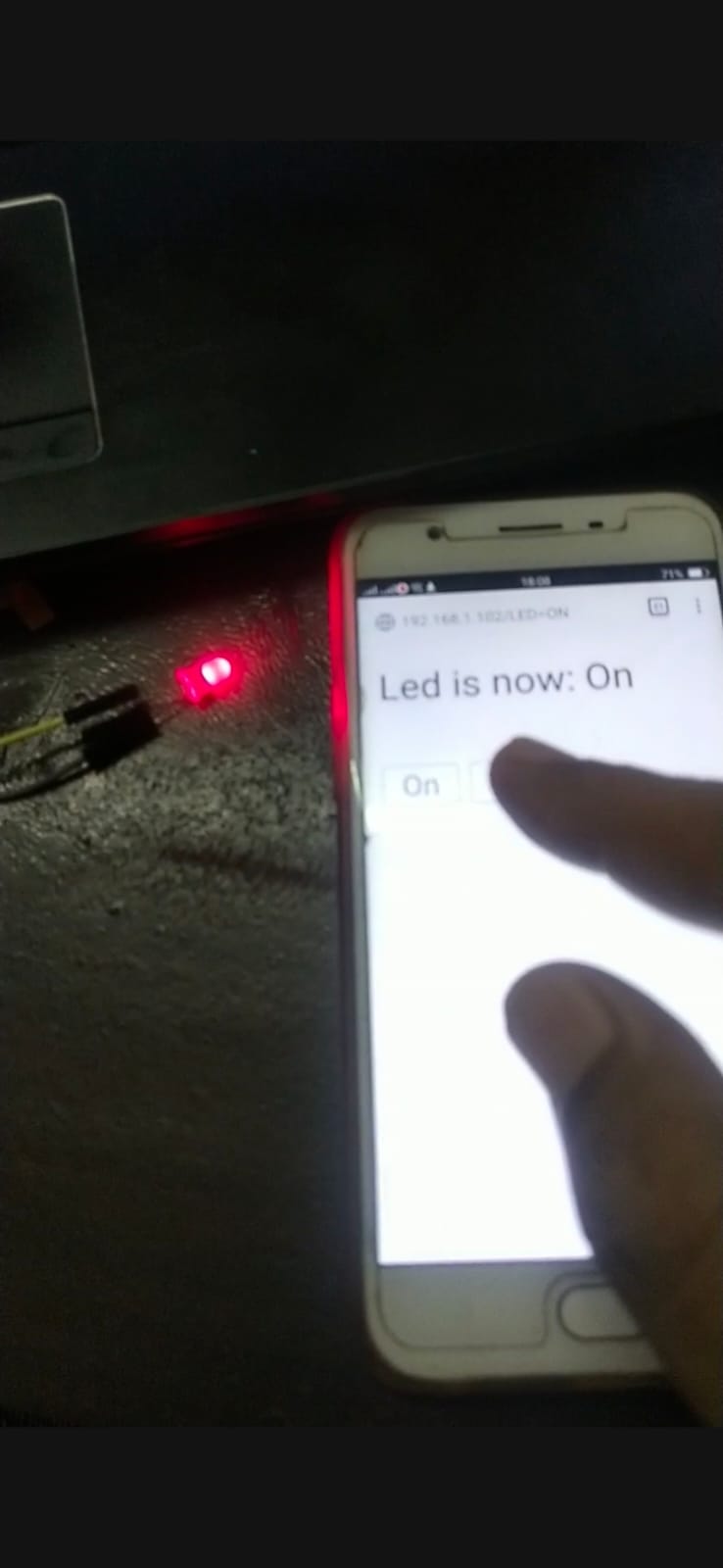
Here is the video and image of the excercise.
2) I also Connected the Two arduino boards using the I2C protocol
I2C communications have become the de facto method of communicating between microcontrollers, microcomputers and a variety of integrated circuits and sensors. It has been around since 1982 and was originally developed for use in television receivers.
In This excercise we will see how it can be used to exchange information between two Arduinos and how it can be used to allows one Arduino to control another one.
Arduino Wire Library
The Arduino has a built-in library for working with I2C called the Wire Library. It makes it very easy to communicate on the I2C bus, and it can configure the Arduino to become either a master or a client .
The Wire library has several useful functions for working with I2C.
- begin() – This initiates the library and sets up the Arduino to be either master or client .
- requestFrom() – This function is used by the master to request data from a client .
- beginTransmission() – This function is used by the master to send data to a specified client .
- endTransmission() – This function is used by the master to end a transmission started with the beginTransmission function.
- write() – Used by both master and client to send data on the I2C bus.
- available() – Used by both master and client to determine the number of bytes in the data they are receiving.
- read() – Reads a byte of data from the I2C bus.
- SetClock() – Used by the master to set a specific clock frequency.
- onReceive() – Used by the client to specify a function that is called when data is received from the master.
- onRequest() – Used by the client to specify a function that is called when the master has requested data.
We will use some of these functions in our sketches.
Arduino I2C Connections
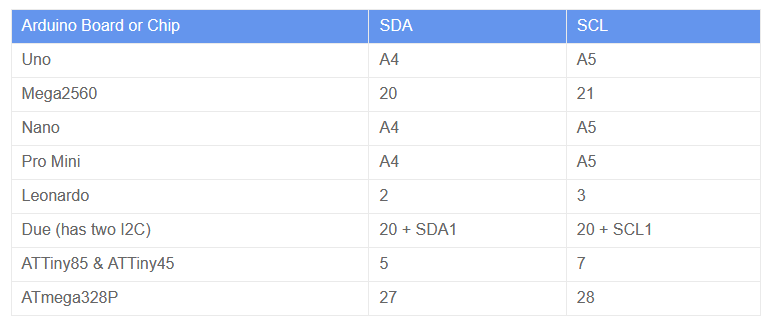
The SDA and SCL connections for I2C are different between Arduino models. The experiments I’m about to show you were done using two Arduino Unos, but you can use other models of the Arduino providing you change the pins accordingly.
I’ve put together a chart to help you get it figured out. It includes some common Arduino boards, as well as a few of the discrete chips. The pinouts for the chips I list (ATTiny and ATmega328P) are with the DIP package, not the surface-mount ones.
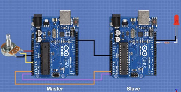
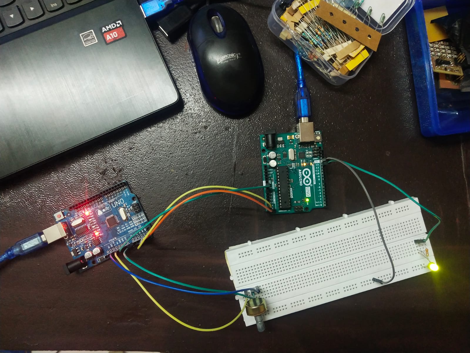
we will hook a potentiometer to the master Arduino and an LED to the client . We will use the potentiometer to control the blink rate of the LED.
This is another simple demonstration, you can build upon it to create something more practical.
It is essentially the same hookup as the previous experiment, with the addition of the potentiometer on the master and the LED on the client .
Note that the LED on the client has been attached to pin 13. As the Arduino Uno has a built-in LED on pin 13 you may eliminate the LED and its dropping resistor if you wish.
The remarks about pull-up resistors also apply to this hookup.
Remote Demo Master Sketch
The sketch for the master side of this experiment is very simple, in some ways the I2C side is even simpler than the one used in the first demonstration. This is because we are just sending data to the client and are not expecting to get any back.
The sketch for the master side of this experiment is very simple, in some ways the I2C side is even simpler than the one used in the first demonstration. This is because we are just sending data to the client and are not expecting to get any back.
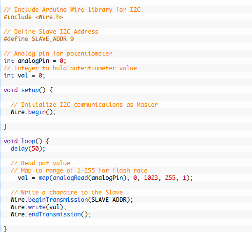
As always we need to include the Wire library at the beginning of the sketch. We also will define a constant to hold the client address.
Since we are using a potentiometer we will need to define both the pin it is connected to and a variable to hold its value.
All that we do in the Setup is to initialize the I2C connection as a master.
In the Loop we read the potentiometer value and map it to a range of 01-255. We need to do that as we are sending one byte of information and can only hold this many values in a single byte.
Note that we reverse the numbering sequence in the Arduino Map function, this is done so that the system behaves the way we expect it to – turning the potentiometer to the right increases the flash rate. As the “flash rate” is specified by a time delay a bigger number being sent will equate to a longer flash rate.
Also note that we don’t send the value 0, which would just hold the LED at one state. We set our range to end at 1 instead.
Now it’s just a matter of sending the byte to the client and repeating the Loop again.
Remote Demo Receive Sketch
The client side needs to receive data from the master and use it to flash the LED.
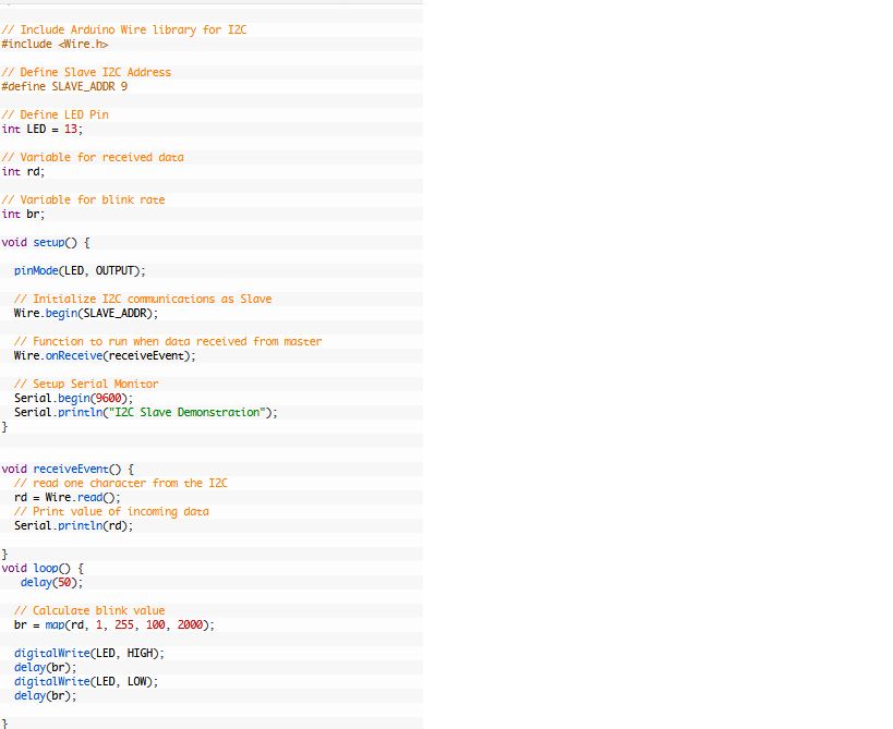
We start with the usual inclusion of the Wire library, as well as defining the client address. We also define a pin for the LED.
A couple of additional variables are defined, one holding the received data while the other carries the time delay value for the blink rate.
In the Setup we set the I/O pin for the LED as an output and initialize the I2C bus. As we use the client address in the begin function the Wire library knows we are acting as a client .
We only need to define an onReceive function, unlike the last demo we are not expecting any requests from the master. We also set up and print to the Serial monitor, we will use the monitor to view the incoming data.
The receiveEvent function reads the incoming data and assigns it to the I variable. It also prints the value to the serial monitor.
Finally, in the Loop we use the incoming data to blink the LED. Once again we use the Map function to accomplish this, changing the incoming values of 1-255 to a wider range. You can experiment with changing this range to make the LED blink faster or slower if you wish.
The last few statements are essentially the Arduino Blink sketch in disguise! We turn the LED on and off for a time period we determined in the last step.
And then we repeat the loop.(Credit:---https://dronebotworkshop.com)
Turning the potentiometer should now vary the LED blink rate on the client .
here is the video and image of the excercise.
This week i also Connected the LCD 1602 to ESP 8266 Node MCU to display the Date and Time using NTP Client.
We studied the datasheet of the 1602 LCD in the last week.
I tried to make an Internet Clock Using NodeMCU ESP8266 and 16×2 LCD without RTC Module. This simple Internet Clock using NodeMCU ESP8266 gets the current Date and Time from NTP Client. Here, NTP stands for Network Time Protocol. (Credit:-https://theiotprojects.com)
We will fetch the time and date from the internet using the ESP8266 controller. Actually, we all know that the internet time clock has a precision of 0.02 to 0.10 seconds. While being on lockdown due to coronavirus, I spent some time browsing the internet and found an Internet Clock that is made using RTC Modules like DS1307, DS3231 or PCF8563 to get the time. But, due to lockdown, there is no availability of any RTC Module.
So I tried making an Internet Clock Using NodeMCU ESP8266 and 16×2 LCD without RTC Module. Instead, I used the NTP client to get the current date and time through the Internet. Actually, while surfing the internet I found some disadvantages as well. The RTC has poor accuracy and requires manual adjustments from time to time to keep date and time-synchronized.
Components Required
These are the components that are required for making this project. All the components are easily available.
- NodeMCU ESP8266
- 16*2 LCD display
- Jumpers
- Breadboard
What is an NTP (Network Time Protocol)?
The Network Time Protocol (NTP) is a TCP/IP Protocol used for clock synchronization between computer systems and data networks. NTP protocol can be used to synchronize all connected devices to Coordinated Universal Time (UTC) within a few milliseconds, for example 50 milliseconds over the public Internet.
Some of the advantages of using NTP are:
- The NTP can be easily hosted on servers hosting different services.
- NTP requires less resource overhead.
- It has minimal bandwidth requirements.
- Even with a minimum CPU usage, NTP can handle hundreds of clients at the same time.
How does NTP work?
The NTP client starts a time-request exchange with the NTP server. As a result of this exchange, the client is ready to compute the link delay and its local offset and adjust its local clock to match the clock at the server’s computer.
These are the connections between NodeMCU & LCD Display.
- RS pin of LCD — D6 pin of NodeMCU
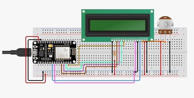
- EN pin of LCD — D5 pin of NodeMCU
- D4 pin of LCD — D1 pin of NodeMCU
- D5 pin of LCD — D2 pin of NodeMCU
- D6 pin of LCD — D3 pin of NodeMCU
- D7 pin of LCD — D4 pin of NodeMCU
Similarly connect pin numbers 1, 5, and 16 of LCD to GND & Pin numbers 2, and 15 to 5V VCC. A 10K Potentiometer should be used at pin number 3 of LCD to adjust the contrast. 5V DC is enough to operate this device.
Libraries Requirement
To make an Internet Clock Using NodeMCU ESP8266 and 16×2 LCD without RTC Module, we need few libraries:
#include <ESP8266WiFi.h>
#include <WiFiUdp.h>
#include <NTPClient.h>
#include <TimeLib.h>
#include <LiquidCrystal.h>
First, we need the NTPClient Library. This library connects the ESP8266 WiFi to a time server, the server sends time information to the module. However, for sending and receiving UDP messages WiFiUdp.h library is used.
Then we have a Time library that converts a Unix timestamp (Unix epoch) into seconds, minutes, hours, day of the week, day, month and year.
The LCD Library is used to interface 16×2 LCD with ESP8266 Board.
Source Code/Program for ESP8266 Internet Clock
Here is a source code for getting NTP Time from Server. Before uploading the code to the NodeMCU ESP8266 Board, you need to make changes in the line below to match your time zone.
NTPClient timeClient(ntpUDP, "asia.pool.ntp.org", 20700, 60000);
Currently, I am staying in India. India is 5 hours and 45 minutes ahead of Coordinated Universal Time (UTC Time). So I converted +5 hr 45 Mins to Seconds.
+5 hr 45 Mins = 5x60x60 + 45×60 = 20700
So change this Timing according to your time Zone and Country in order to get correct time.
Also in the below code, make changes to the Wifi SSID & Password.
Final Code/sketch
#include <ESP8266WiFi.h>
#include <WiFiUdp.h>
#include <NTPClient.h>
#include <TimeLib.h>
#include <LiquidCrystal.h>
LiquidCrystal lcd(D6, D5, D1, D2, D3, D4);


char* ssid = "Alsan Air WiFi 4";  //wifi ssid
char* password = "11122235122@kap1";   //wifi password

WiFiUDP ntpUDP;


NTPClient timeClient(ntpUDP, "asia.pool.ntp.org", 20700, 60000);

char Time[ ] = "TIME:00:00:00";
char Date[ ] = "DATE:00/00/2000";
byte last_second, second_, minute_, hour_, day_, month_;
int year_;


void setup() {

  Serial.begin(115200);
  lcd.begin(16, 2);                 // Initialize 16x2 LCD Display
  lcd.clear();
  lcd.setCursor(0, 0);
  lcd.print(Time);
  lcd.setCursor(0, 1);
  lcd.print(Date);

  WiFi.begin(ssid, password);
  Serial.print("Connecting.");

  while ( WiFi.status() != WL_CONNECTED ) {
    delay(500);
    Serial.print(".");
  }
  Serial.println("connected");
  timeClient.begin();
}


void loop() {

  timeClient.update();
  unsigned long unix_epoch = timeClient.getEpochTime();    // Get Unix epoch time from the NTP server

  second_ = second(unix_epoch);
  if (last_second != second_) {


    minute_ = minute(unix_epoch);
    hour_   = hour(unix_epoch);
    day_    = day(unix_epoch);
    month_  = month(unix_epoch);
    year_   = year(unix_epoch);


    Time[12] = second_ % 10 + 48;
    Time[11] = second_ / 10 + 48;
    Time[9]  = minute_ % 10 + 48;
    Time[8]  = minute_ / 10 + 48;
    Time[6]  = hour_   % 10 + 48;
    Time[5]  = hour_   / 10 + 48;


    Date[5]  = day_   / 10 + 48;
    Date[6]  = day_   % 10 + 48;
    Date[8]  = month_  / 10 + 48;
    Date[9]  = month_  % 10 + 48;
    Date[13] = (year_   / 10) % 10 + 48;
    Date[14] = year_   % 10 % 10 + 48;

    Serial.println(Time);
    Serial.println(Date);

    lcd.setCursor(0, 0);
    lcd.print(Time);
    lcd.setCursor(0, 1);
    lcd.print(Date);
    last_second = second_;

  }
  delay(500);
}
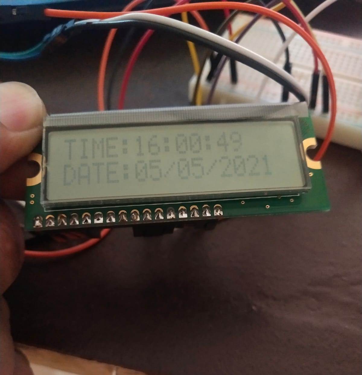
Once the code is uploaded, the ESP8266 will try connecting to the Network. After it connects to Network, the LCD will start displaying the correct time and date.
Here is the Video and image of the whole excercise.
Serial Communication Vs Parallel Communication :-
The key difference between Serial and Parallel Communication is that in serial communication data transmission occurs bit by bit at a time while in parallel communication multiple bits transmit at a time. However, though the data is transmitted bit by bit, serial communication is fast for long distances and high frequencies. But, parallel communication is fast for short distances and low frequencies but slower for long distances and high frequencies.
In data communication, the data travels from the source device or sender to the destination device or the receiver. There are multiple devices connected to share data. Serial and parallel communication are two ways of transmitting data from the sender to receiver.
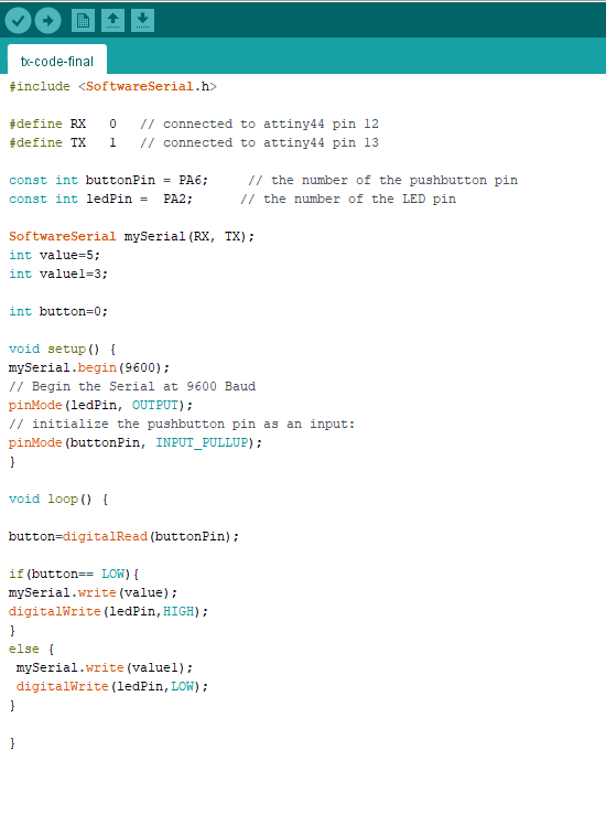
Serial interfacing is like what we have done in most of the boards we made in Fab Academy like (Hello Echo) to send signal through one pin which is Tx and receive the signal through another pin which is Rx. So it make it simple instead of using one board and FTDI I will be using two boards and connect Tx of the 1st board to Rx of the second board and vice versa.
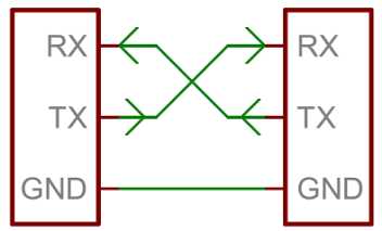

I wrote the above code by configuring the Tx and Rx pins at each board, sending Hello from the tx board, Receiving the serial data from the rx board that has a LED and if there were data through serial bus the LED should blink. I uploaded the code using my Fab ISP on both of the boards then I connected then to each other using the serial connection TX,RX,VCC,GND.
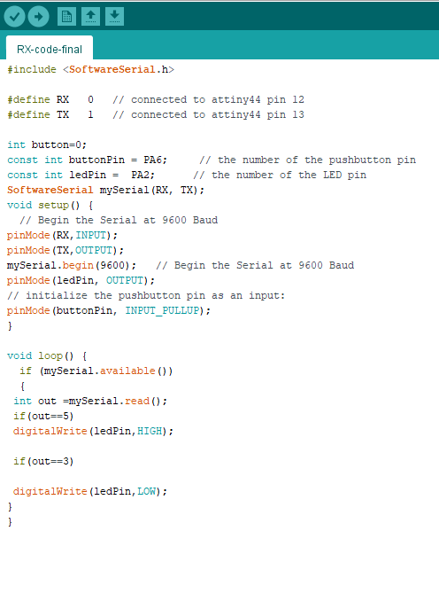
Here is the Video Of the excercise
The Files of this week can be downloaded here