Welcome to Berytech Fab Lab


So the objective of those two weeks was to discover and experience how to design and build a mechanical machine that can accomplish a certain goal or objective by a system of mechanical components, electric circuit, and a controlling code.
This week had a wide range of ideas that could be done. Many ideas could be found in previous Fab Academy years and on other online resources. We can make a CNC Machine, a plotter, laser cutter, 3d printer and many other more, all of which have the same main concept, a sytem of stepper and servo motors, that control a specific head, to produce a specific final product.
Group Assinment
We had a Group Assignment for two week.
A Machine is an apparatus using mechanical power and having several parts, each with a definite function and together performing a particular task.
Machines Used
The main machine used in this week's assignment is the 3d printer.
In this group project first, we searched for the available components in the lab. Rods, stepper motors, servo motors, linear motion bearings, screws …
The rods we found were L = 40 cm and Diameter = 8 mm so we decided to do a 2 axes CNC pen plotter that will be limited to the dimensions of the rods in which it can draw up to an A3 size.
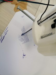
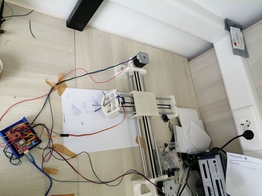
Our machine will be a pen plotter ; it can be placed on the floor and make drawings
The project is divide into 3 parts and distributed on the group members:
The components used:
Part 1
Part 2
Part 3
Part 4
Part 5
Part 6
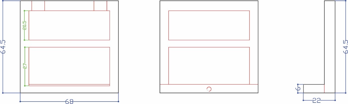
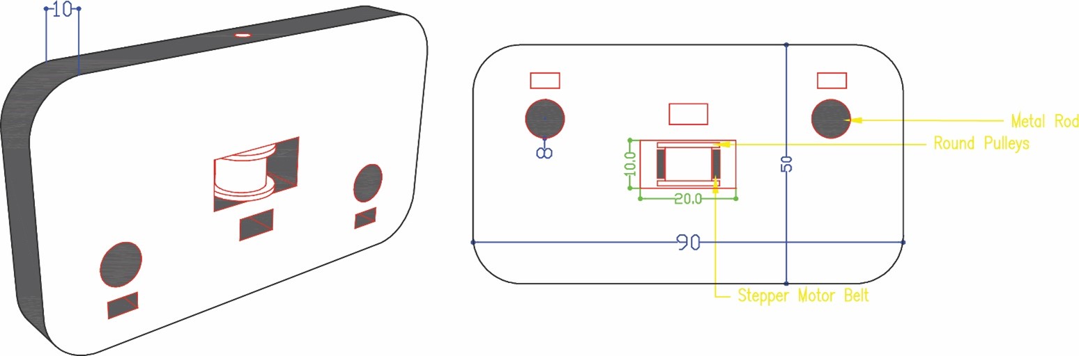
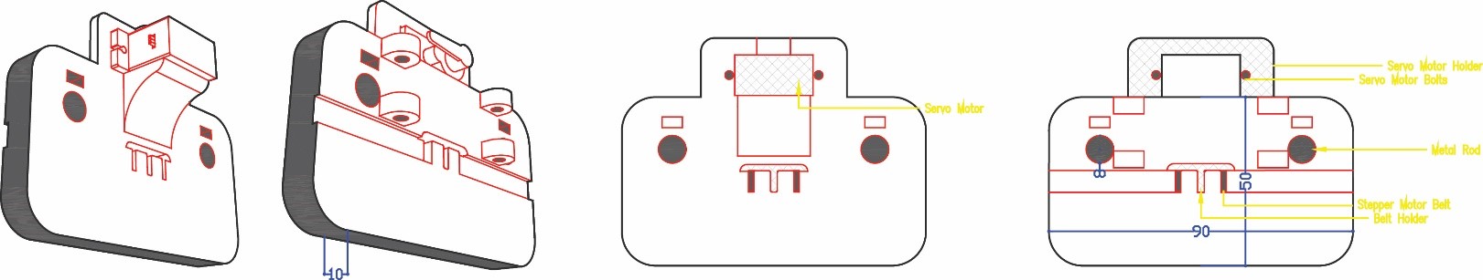
We started by drawing the first phase of the project part two the servo motor holder and part one parallel to it. Taking into consideration the fixed measurements of the components 8 mm rods that will be fixed perpendicularly to the parts, servo motor, pulleys, and stepper motor belt.
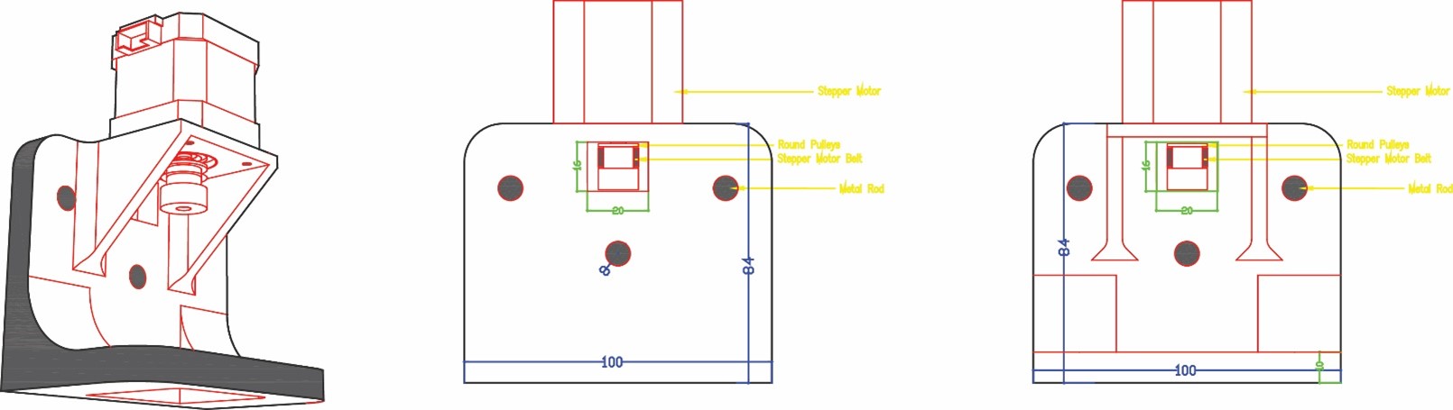
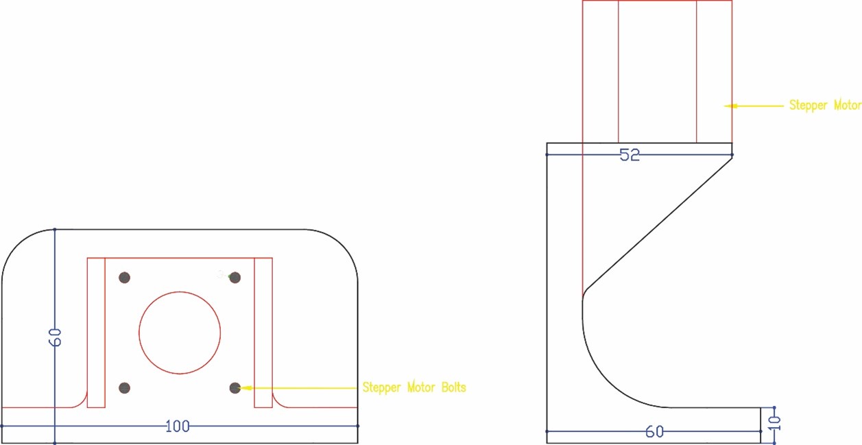
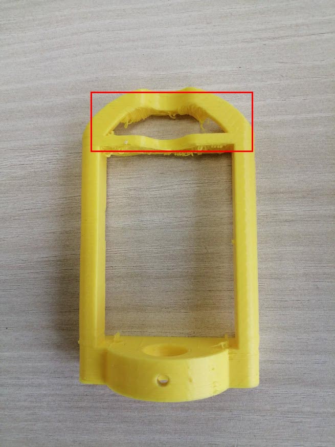
Then in phase two we measured the stepper motors and started designing part three to hold the motors taking into consideration the pulleys and the belt movement. The stepper motor holder is designed with an opening inside it a rectangle 18 x 16 mm that will include the pulley and the belt taking into consideration its movement without having friction. We also did a 45° support to hold the motor without breaking.
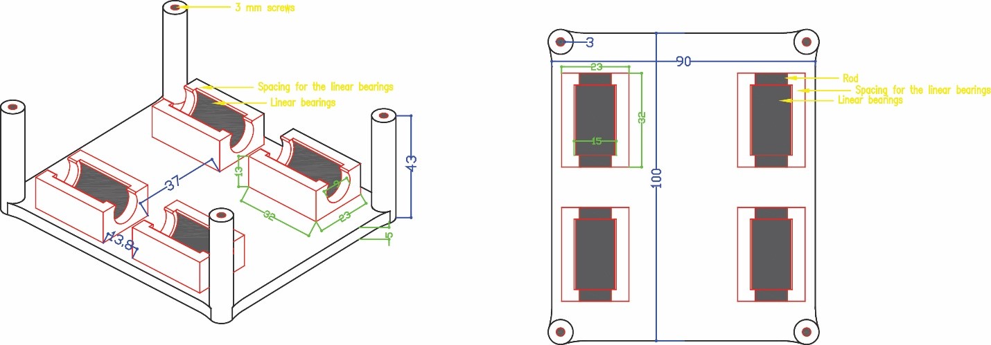
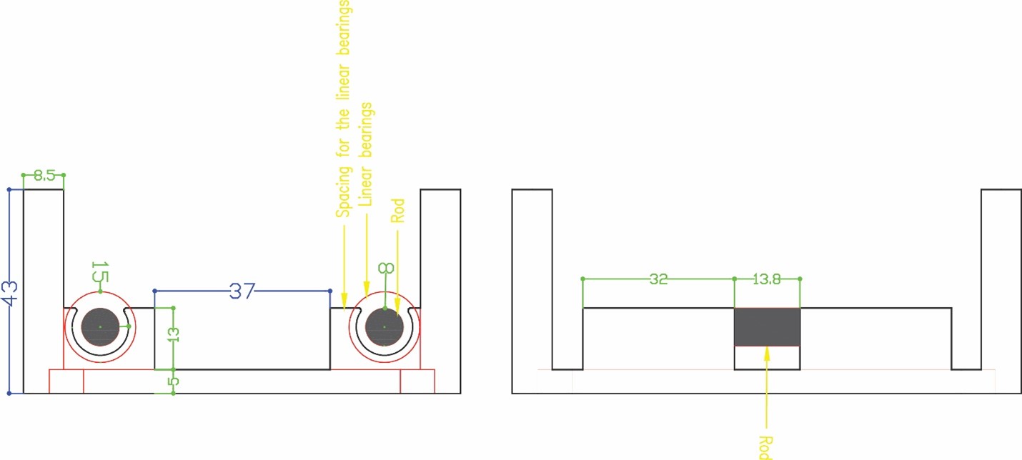
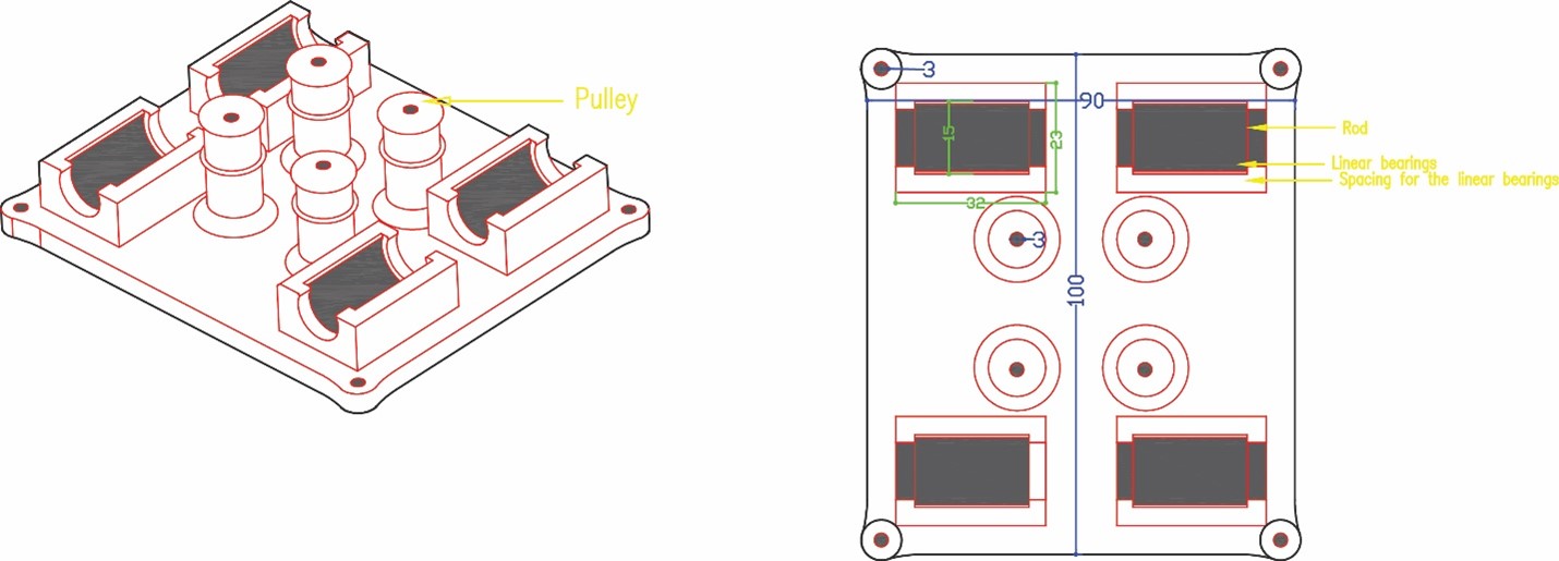
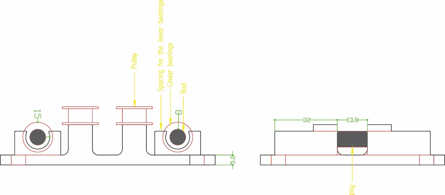
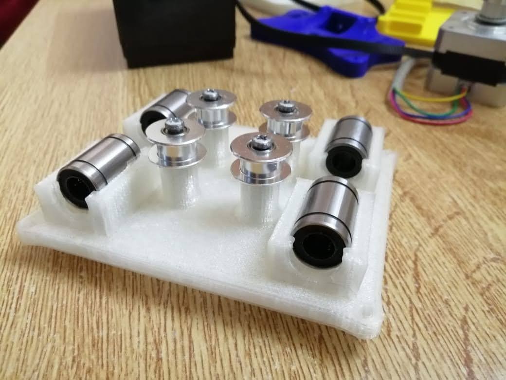
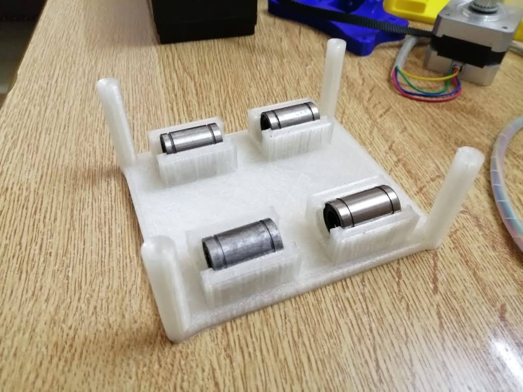
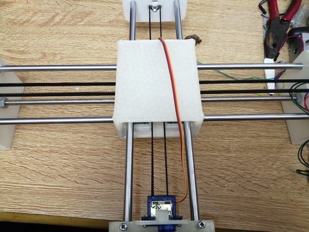
Phase three we designed the box holder that will include the linear bearings with 8 mm shafts so that the rods will pass inside it and the holder will move in two axes x and y. We measured the bearings 15 mm outer diameter and 8 mm inner diameter for the rods with a length of 24 mm. To hold the bearings, we drew the outer diameter and did an offset with a smaller diameter 12 mm so that the bearing can sit inside the holder without falling. The upper bearing will be perpendicular to the lower part allowing the machine to move along the metal rods in the two axes freely. We designed the bottom holder part five taking into consideration the four pulleys that will guide the stepper motor belt.
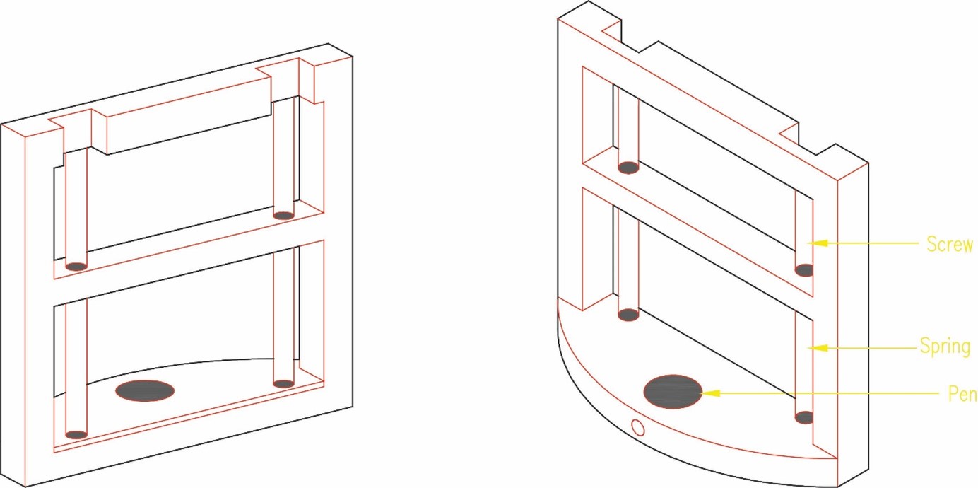
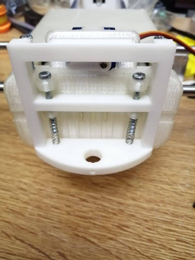
The pen holder will be fixed to the servo motor with screws allowing it to turn and raise it in the z axis up and own. It will include a pen and springs to move and draw whatever is sent to it.
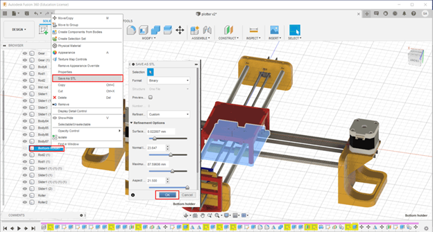
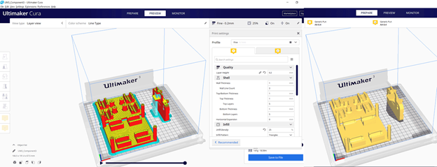
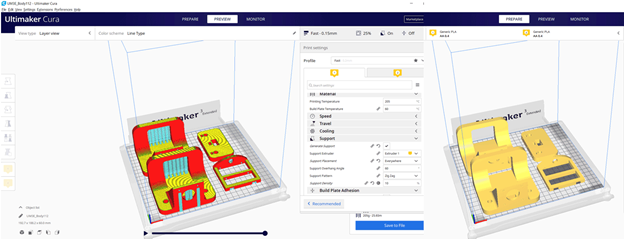
In the Fusion 360 file we have to save each part alone as. stl to prepare it for 3d printing.
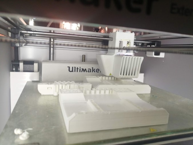
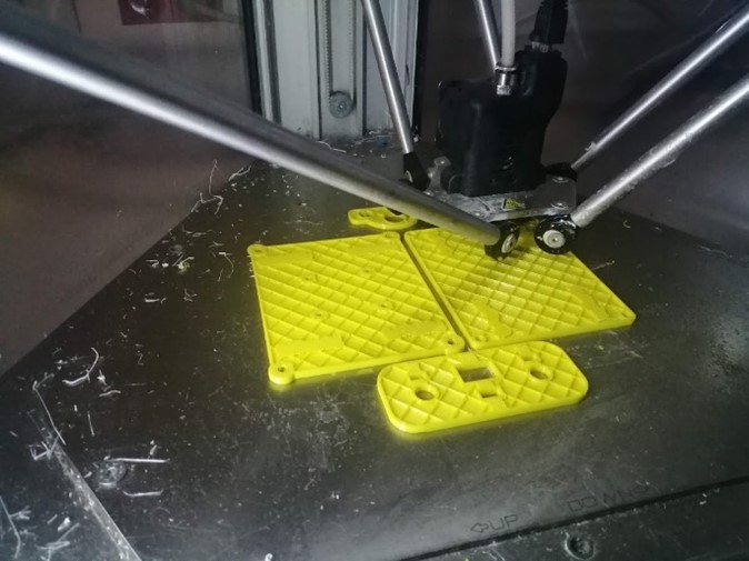
In total we have seven parts for 3d printing. In the first printing trial we used two 3D printers Delta WASP2040 and Ultimaker 3 Extended. In the second printing we used Ultimaker 3 and another Ultimaker 3 Extended. Ultimaker Cura slicer to prepare the Gcodes. The settings for both trials are:
All design files can be dowloaded from the following LINK
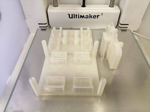
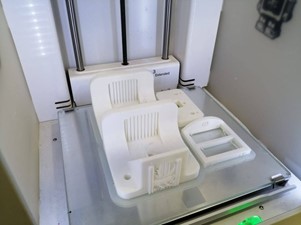
In the first printing we faced a lot of problems related to the measurements. The printers were not accurate enough.
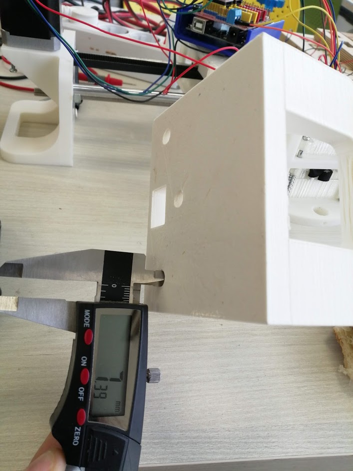
For the rods in the Ultimaker the circle for the rod was very small 7.3 mm instead of 8 mm and it did not fit inside the print.
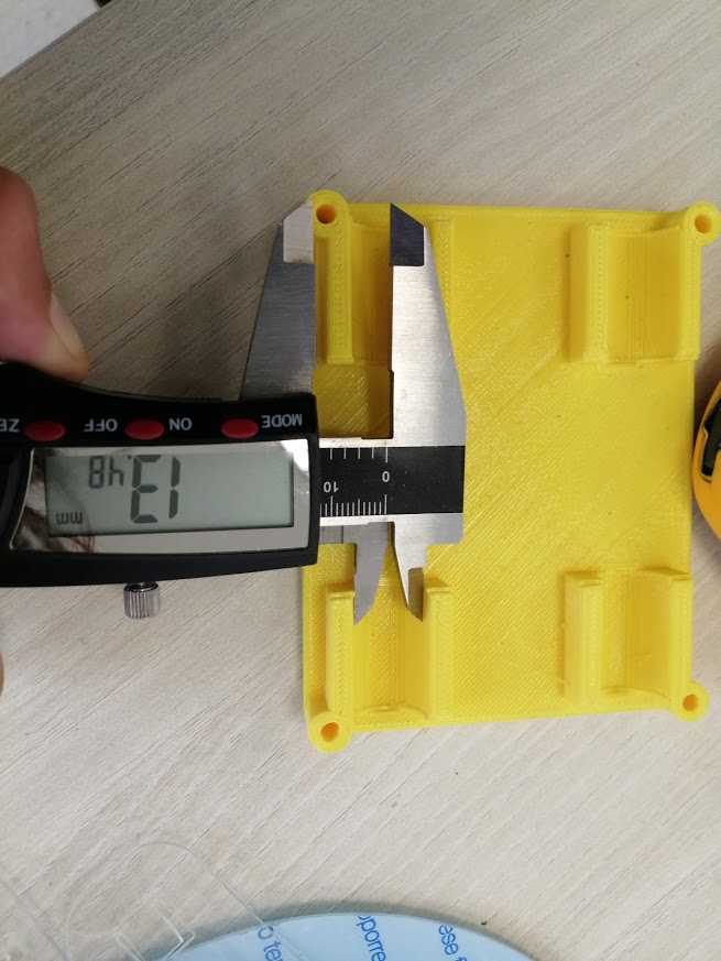
Also, the space for the linear bearings was small and they did not fit easily in the top and bottom holders. Diameter should be 15 mm after printing it was 13.4 mm.
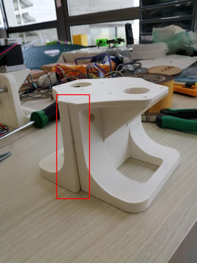
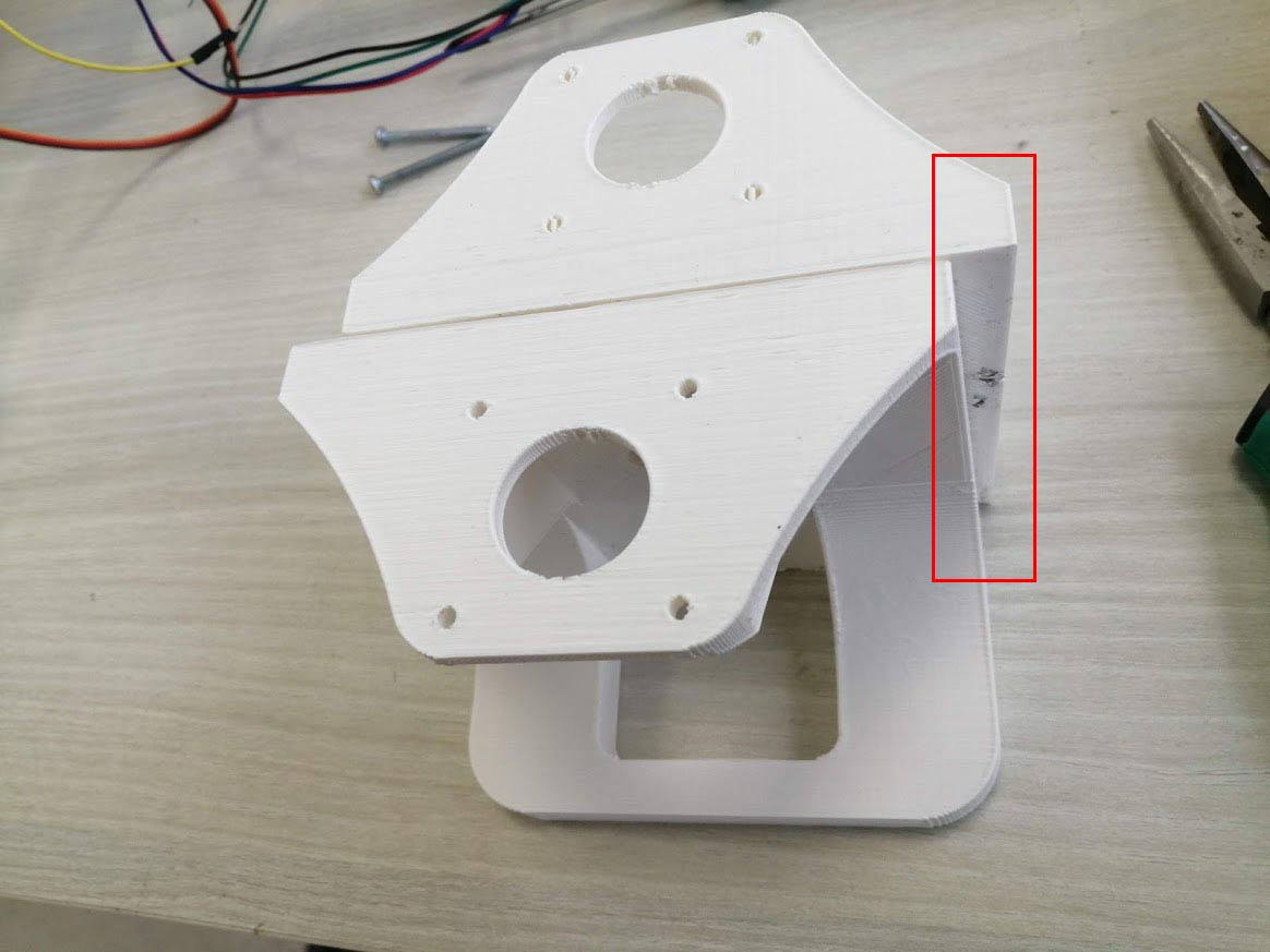
In the Ultimaker printer we had a problem in the calibration x and y axes. After finishing the prints, they were not straight and distorted. So, the machine cannot be assembled.
Then while checking the pen holder we discovered that we did not give the servo motor enough space to rotate and move the part.
After checking all these problems, we went back to the fusion file and did some edits in the file design and measurements.
First, we assembled the bottom holder inserted the linear motion bearings with the pulleys.
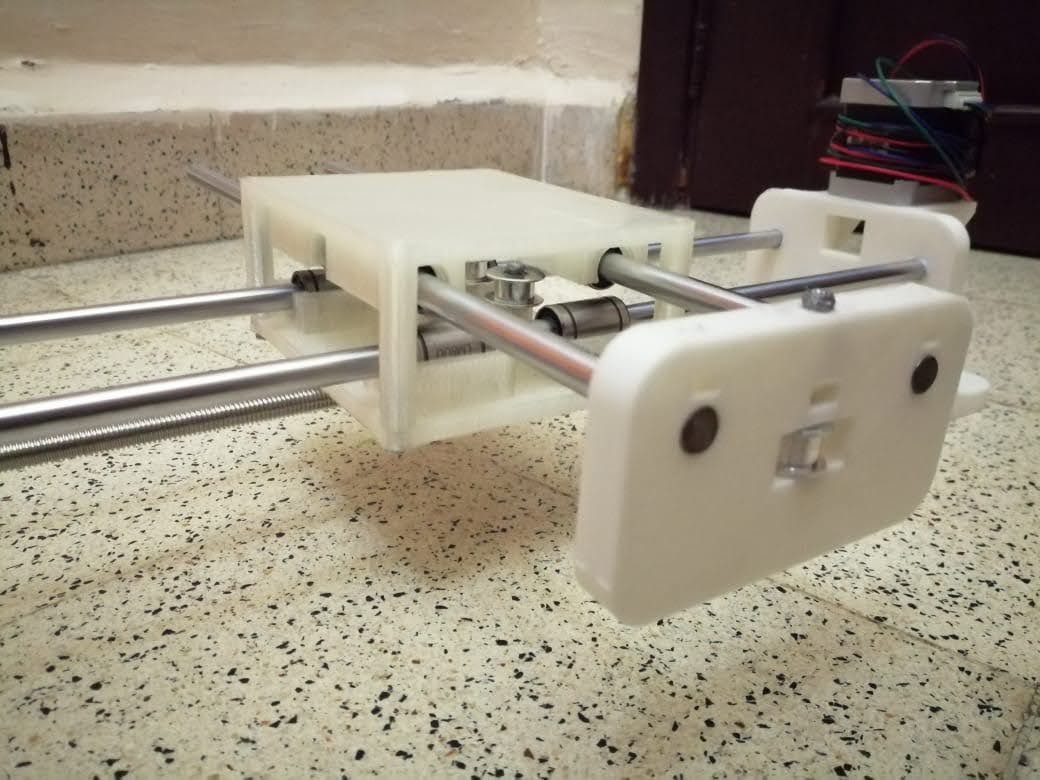
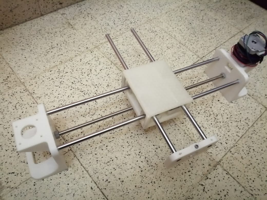
Our CNC pen plotter machine has 2 axes with 2 stepper motors, the x and y axes have limitations in length because they are on rods limited to 40cm.
The pen is controlled by a servo motor. The servo motor is connected to the pen holder with springs and a pen inserted inside it that lift it up and down.
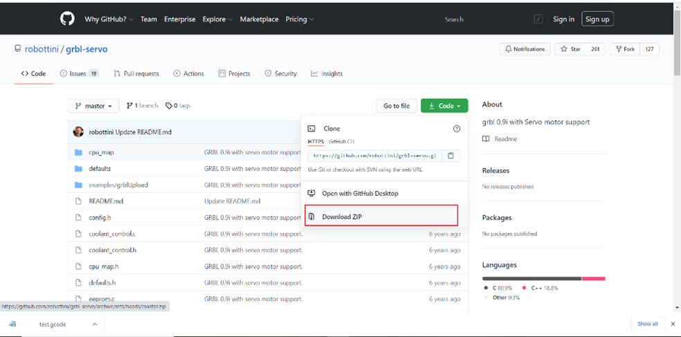
We used a grbl-Servo library to control the Arduino and the motors.
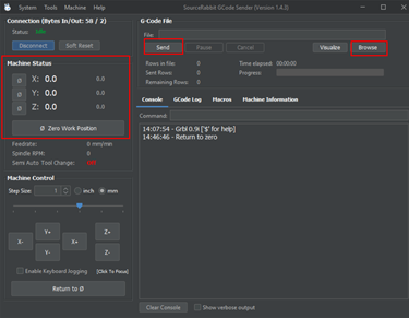
Then we connected the Arduino to a Gcodes sender. In our case we used Source Rabbit gcode sender. We had to modify some settings to match our machine gears and wheels dimensions. The gcode was generated in fabmodules and we had to modify it in notepad in order to adjust some settings to work with the grbl-Servo we used.
The different steps done are detailed below:
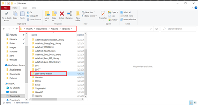
First, we downloaded the grbl libraryand add to the Arduino IDE libraries folder. We used the grbl-servo library since we have a servo motor, and we have to control it in our machine using the Gcode.
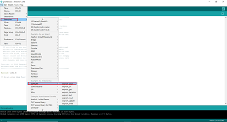
Then in Arduino we have to click on File tab – Examples – EEPROM – eeprom_clear We did this step to erase the chip and reprogram it.
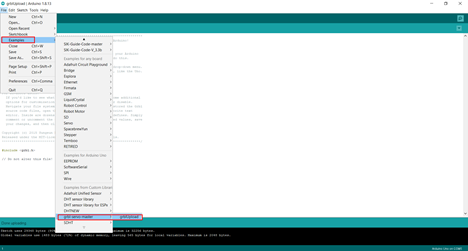
Now we will upload the grbl from the examples folder in Arduino. File tab – Examples – grbl-servo-master – grblUpload
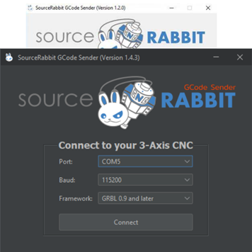
We downloaded the SourceRabbit gcode sender and installed it.
And then we connected to the port COM3 and Baud 115200 to match the connected Arduino port.
Once we are connected, we need to change some settings. The grb; settings should be related to our machine gears and dimensions.
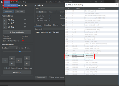
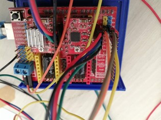
We will be using an Arduino with CNC Shield. The shield itself consists of the big red board with smaller red boards that are used to control motors. The smaller boards are called the motor driver boards and correspond to the X-, Y-, and Z-axes.
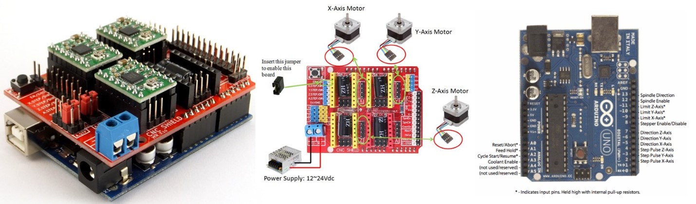
We will plug a Stepper motor driver A4988 and place jumpers for micro stepping. Then we will connect the 2 stepper motors that are for the X & Y axis and the servo motor on pin 11.
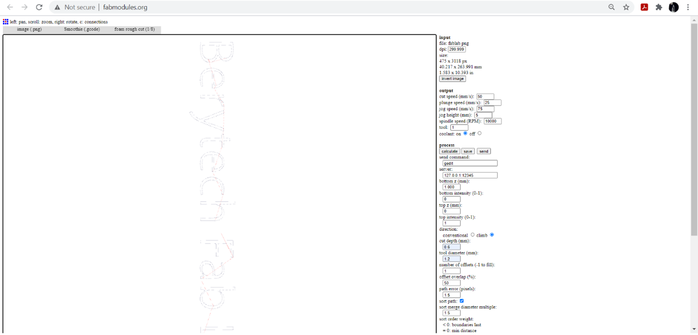
We used fabmodules to generate the gcode with the below settings
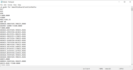
After generating the Gcode we modified it using notepad in order to control the servo motor.
Make sure the machine board is connected to Source Rabbit Gcode Sender then click on browse and select the modified Gcode then click send. Before sending the file, we had to make sure of our work position 0,0,0.