Welcome to Berytech Fab Lab

+961 4 533 040 ext. 1029 9:00 AM - 5:00 PM (Mon-Fri)

Interface and Application Programming

So the objective of this week is to get introduced to using Code to Create Applications that Interface with input and output devices. According to Wikipidia, "In computer programming, an application programming interface (API) is a set of subroutine definitions, protocols, and tools for building application software. In general terms, it is a set of clearly defined methods of communication between various software components. A good API makes it easier to develop a computer program by providing all the building blocks, which are then put together by the programmer. An API may be for a web-based system, operating system, database system, computer hardware or software library. An API specification can take many forms, but often includes specifications for routines, data structures, object classes, variables or remote calls. POSIX, Windows API and ASPI are examples of different forms of APIs. Documentation for the API is usually provided to facilitate usage and reimplementation." There are many laguages that could be used to build applications that interface with Input and Output devices. Out of which are C++, JAVA, Python, Arduino, and Processing. In this section, we will learn on how to collect data from sensors through a microcontroller, and how to use coding to Simulate and Visualize the measurements in Graphical representations.

Group Assinment
The group assginment was to Compare as many tool options as possible.

An application program interface (API) is a set of routines, protocols, and tools for building software applications. Basically, an API specifies how software components should interact. Additionally, APIs are used when programming graphical user interface (GUI) components.

Compare as many tool options as possible

The assignment this week was to Compare as many tool options as possible.

So our idea was to compare the various options we can use to interface with out inputs and otputs.

Test1 - Dimming LED with processing:

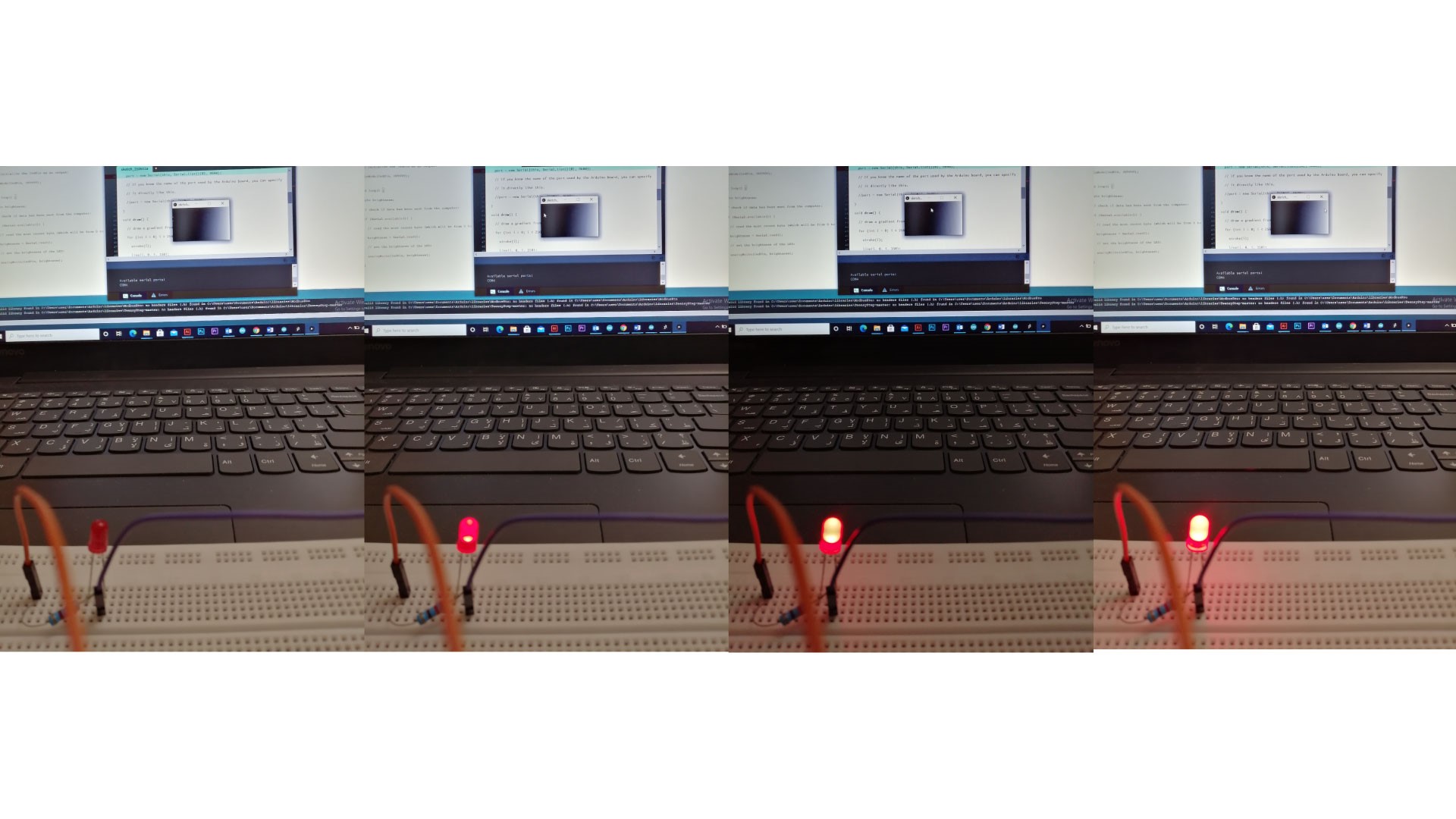
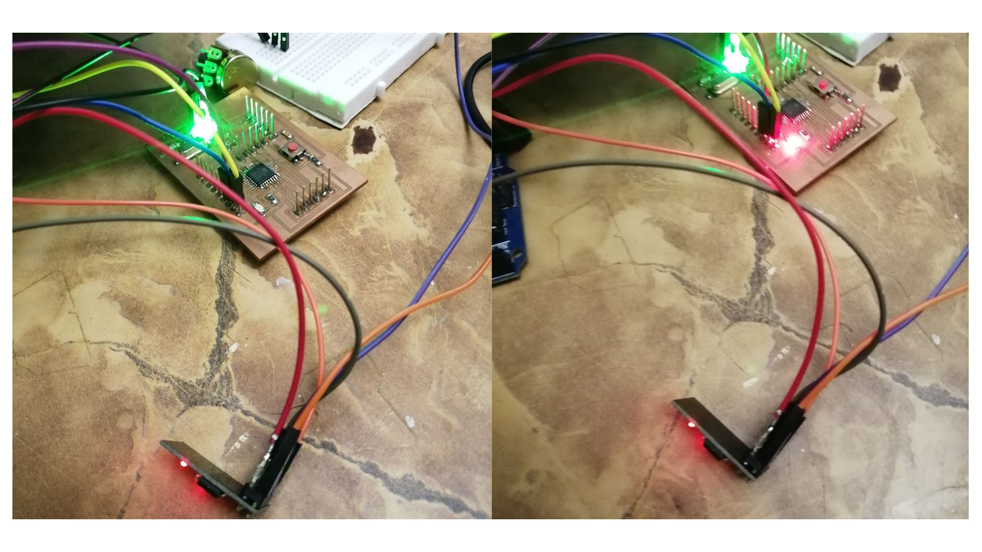
We will use Processing to control the brightness of the LED according the movement of the mouse.

Arduino code

const int ledPin = 9; // the pin that the LED is attached to void setup() { // initialize the serial communication: Serial.begin(9600); // initialize the ledPin as an output: pinMode(ledPin, OUTPUT); } void loop() { byte brightness; // check if data has been sent from the computer: if (Serial.available()) { // read the most recent byte (which will be from 0 to 255): brightness = Serial.read(); // set the brightness of the LED: analogWrite(ledPin, brightness); } }

Processing code

// Dimmer - sends bytes over a serial port // by David A. Mellis // This example code is in the public domain. import processing.serial.*; Serial port; void setup() { size(256, 150); println("Available serial ports:"); // if using Processing 2.1 or later, use Serial.printArray() println(Serial.list()); // Uses the first port in this list (number 0). Change this to select the port // corresponding to your Arduino board. The last parameter (e.g. 9600) is the // speed of the communication. It has to correspond to the value passed to // Serial.begin() in your Arduino sketch. port = new Serial(this, Serial.list()[0], 9600); // If you know the name of the port used by the Arduino board, you can specify // it directly like this. //port = new Serial(this, "COM1", 9600); } void draw() { // draw a gradient from black to white for (int i = 0; i < 256; i++) { stroke(i); line(i, 0, i, 150); } // write the current X-position of the mouse to the serial port as // a single byte port.write(mouseX); }

Board

photo


Test 2 - Testing Grasshopper

Controlling Servo Motor with Grasshopper

As I use Rhinoceros and Grasshopper for parametric designs, I was interested to know how to connect Arduino boards with sensors and motors to read data. First, I had to download and install FIREFLY plugin which is used to connect grasshopper to micro-controllers linking the digital and physical world.
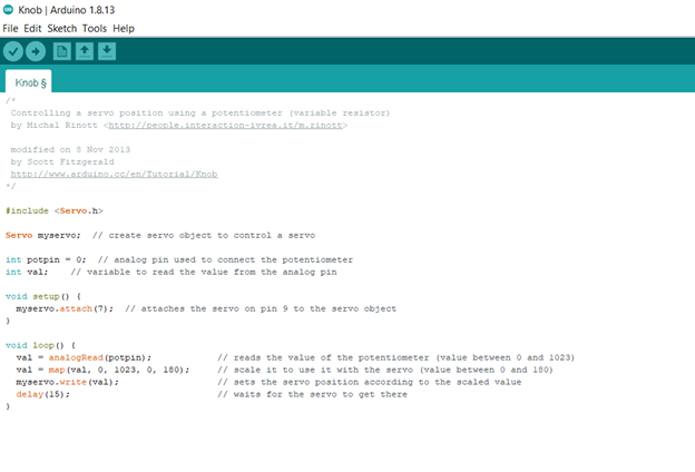
Firefly Website

I wanted to test servo motors with the Arduino code related to servo motors.

Arduino code

/* Controlling a servo position using a potentiometer (variable resistor) by Michal Rinott modified on 8 Nov 2013 by Scott Fitzgerald http://www.arduino.cc/en/Tutorial/Knob */ #include Servo myservo; // create servo object to control a servo int potpin = 0; // analog pin used to connect the potentiometer int val; // variable to read the value from the analog pin void setup() { myservo.attach(7); // attaches the servo on pin 9 to the servo object } void loop() { val = analogRead(potpin); // reads the value of the potentiometer (value between 0 and 1023) val = map(val, 0, 1023, 0, 180); // scale it to use it with the servo (value between 0 and 180) myservo.write(val); // sets the servo position according to the scaled value delay(15); // waits for the servo to get there }

Grasshopper Data Tree

photo

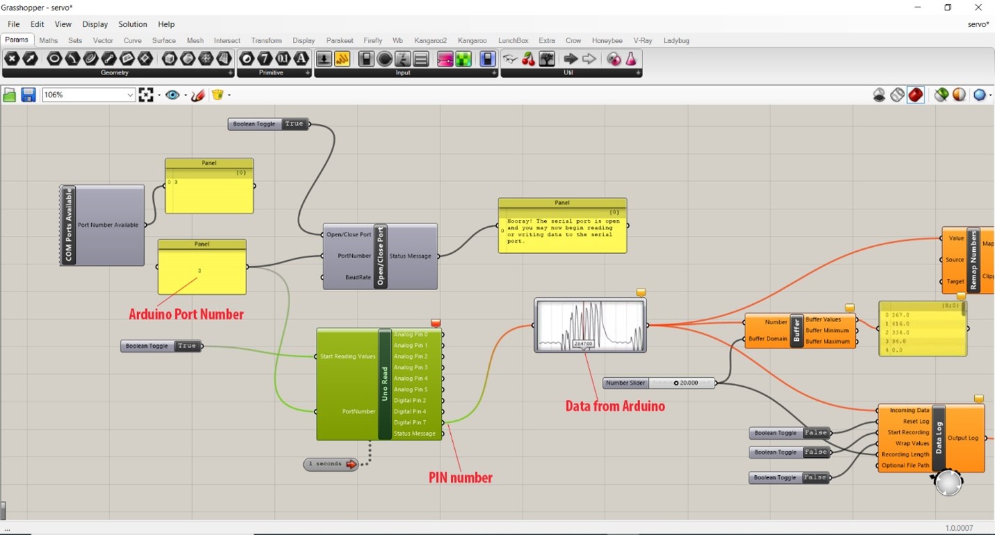
In the Arduino port number, we have to check the COM and change it in the panel.
In PIN number it should be the same as the PIN in the Arduino code that is connected to the servo motor.
Data from Arduino is read once we upload the code.

photo

Test 3 - Testing BLYNK

Blynk is a simple and easy to implement user interface, it facilitates the access to our project via mobile phone. We used the application Blynk to turn ON and OFF the built in LED with WiFi connection using esp8226.

    In order to use it:
  • I downloaded the Blynk application on my Iphone,
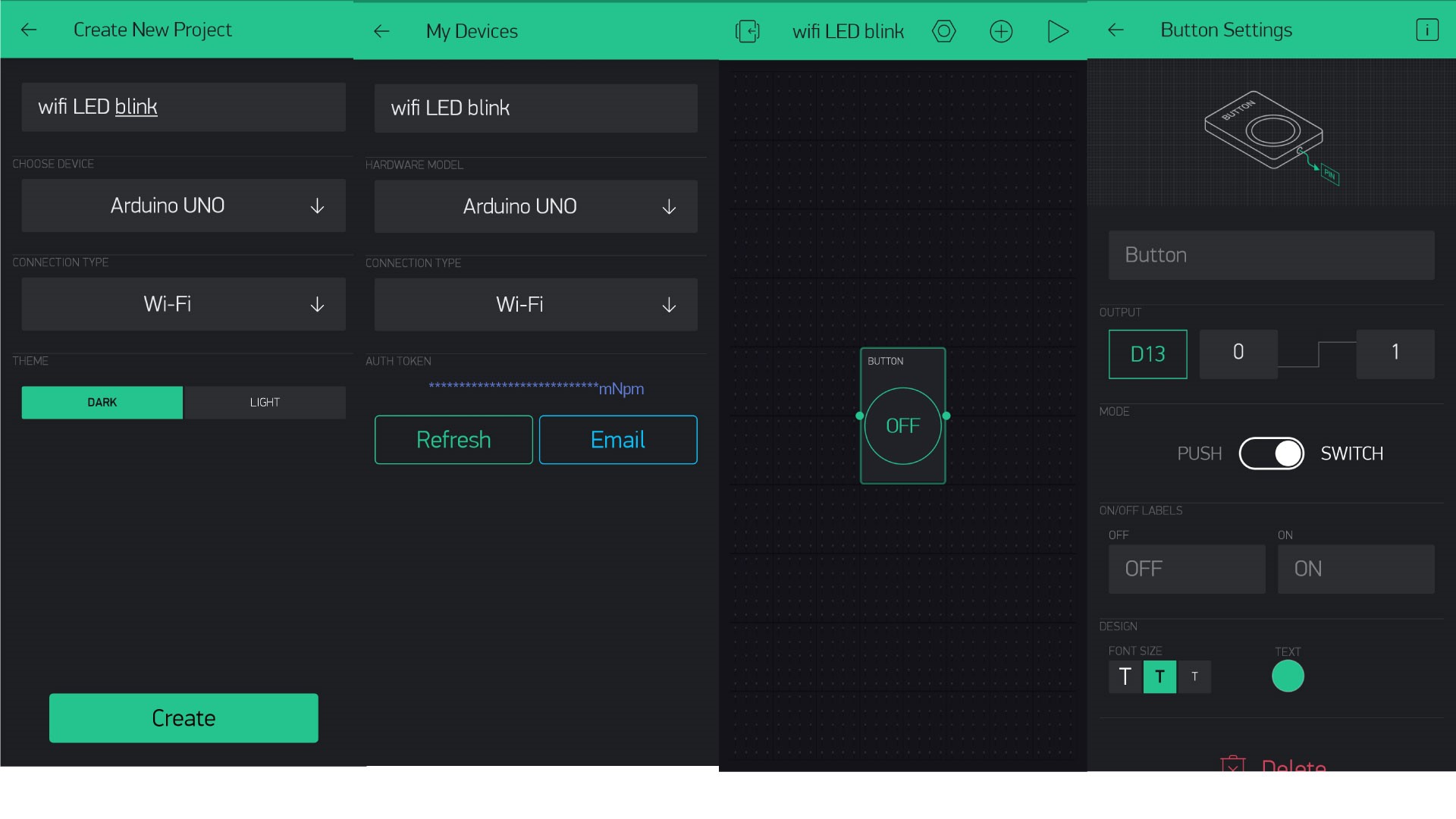
  • Authentication code will be sent by email, copy the code, since it will be placed in the Arduino Code.
    Note that the wifi preferences must be changed according to your router settings.

    Arduino code

    #define BLYNK_PRINT Serial #include #include #include #define BLYNK_PRINT Serial #include #include // You should get Auth Token in the Blynk App. // Go to the Project Settings (nut icon). char auth[] = "FQlB6sMx-4cpKpxt47Qyhuh-qwAH9HPP"; // Your WiFi credentials. // Set password to "" for open networks. char ssid[] = "Chaaban"; char pass[] = "330330330"; // Hardware Serial on Mega, Leonardo, Micro... //#define EspSerial Serial1 // or Software Serial on Uno, Nano... //#include SoftwareSerial EspSerial(2, 3); // RX, TX // Your ESP8266 baud rate: #define ESP8266_BAUD 38400 ESP8266 wifi(&EspSerial); void setup() { // Debug console Serial.begin(9600); // Set ESP8266 baud rate EspSerial.begin(ESP8266_BAUD); delay(10); Blynk.begin(auth, wifi, ssid, pass); // You can also specify server: //Blynk.begin(auth, wifi, ssid, pass, "blynk-cloud.com", 80); //Blynk.begin(auth, wifi, ssid, pass, IPAddress(192,168,1,100), 8080); } void loop() { Blynk.run(); // You can inject your own code or combine it with other sketches. // Check other examples on how to communicate with Blynk. Remember // to avoid delay() function! }

    The built-in LED is controlled using the phone via blynk app, when the button is pressed, the LED will be turned ON.