Welcome to Berytech Fab Lab

So the objective of the forth week is to learn how to produce a PCB (Printed Circuit Board) in the Fab Lab. There are many different ways that can be used to produce a PCB, such as CNC milling or using the Etching Method. However, the Etching method is not advised due to the toic chemicals used in the process. Thus we are going to discover and test the CNC milling method in this assignment.
Group Assinment
The group assginment was to characterize the specifications of our PCB production process.
PCB stands for "Printed Circuit Board." A PCB is a thin board made of fiberglass, composite epoxy, or other laminate material. Conductive pathways are etched or "printed" onto board, connecting different components on the PCB, such as transistors, resistors, and integrated circuits.
Machines Used
The main machine used in this week's assignment is the Desktop CNC Machine.
In this week titled "Electronics Production", the Group Assginment was to characterize the specifications of our PCB production process using the milling machine machine available in the lab. Using copper sheets with two bits 0.4 mm and 1.2 mm as a group we did a test to check paths with different thicknesses using MDX-40 milling machine. In part one of the assignment, we show how we extracted the needed images to do the milling job. In part two, w showed how the g.code was generated on fab modules. And in Step 3, we show how to setup the machine and send the job file to the machine.
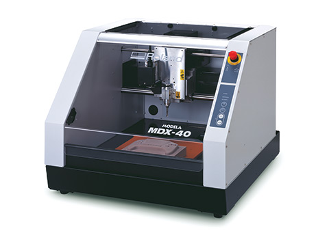
This machine is a subtractive machine technology and it can 2D and 3D Mill. There are many settings that need to be checked and changed before any milling process that depend on the material and the bit being used. All these settings affect directly the results needed or quality to be achieved. The settings are:

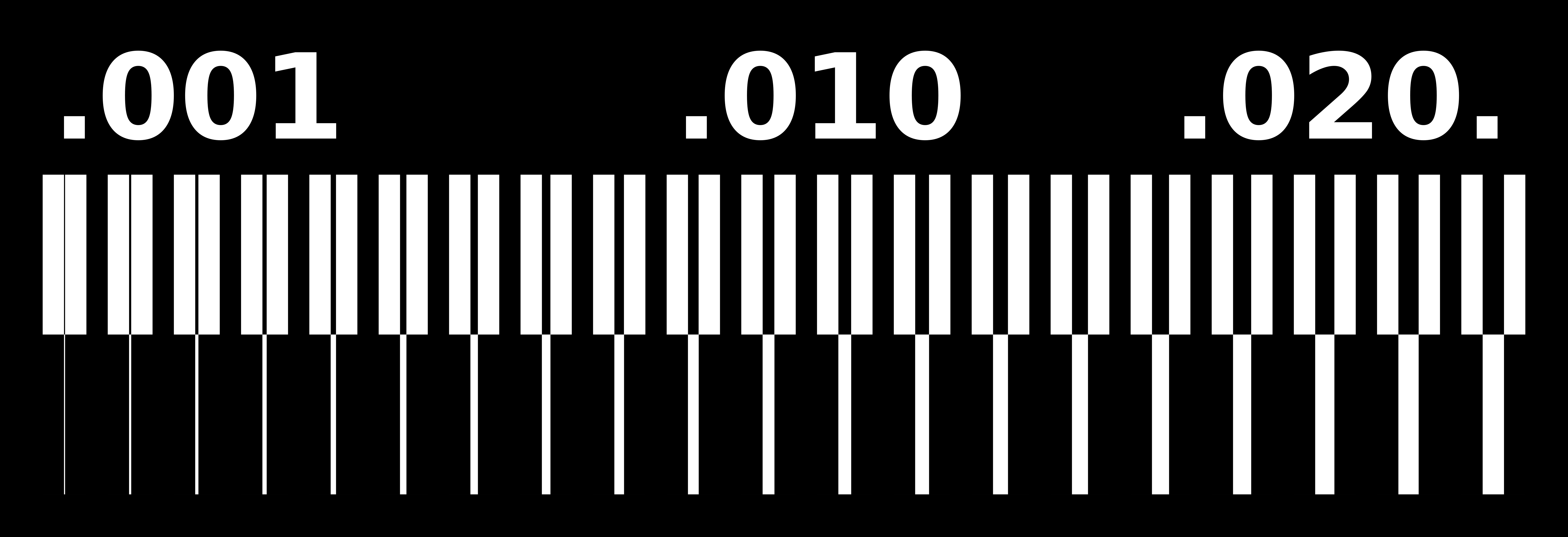
Before milling the test file we had to create 2 images, one for the internal traces and one for the outline cutout. For that we did the following:
The steps are shown in the image below: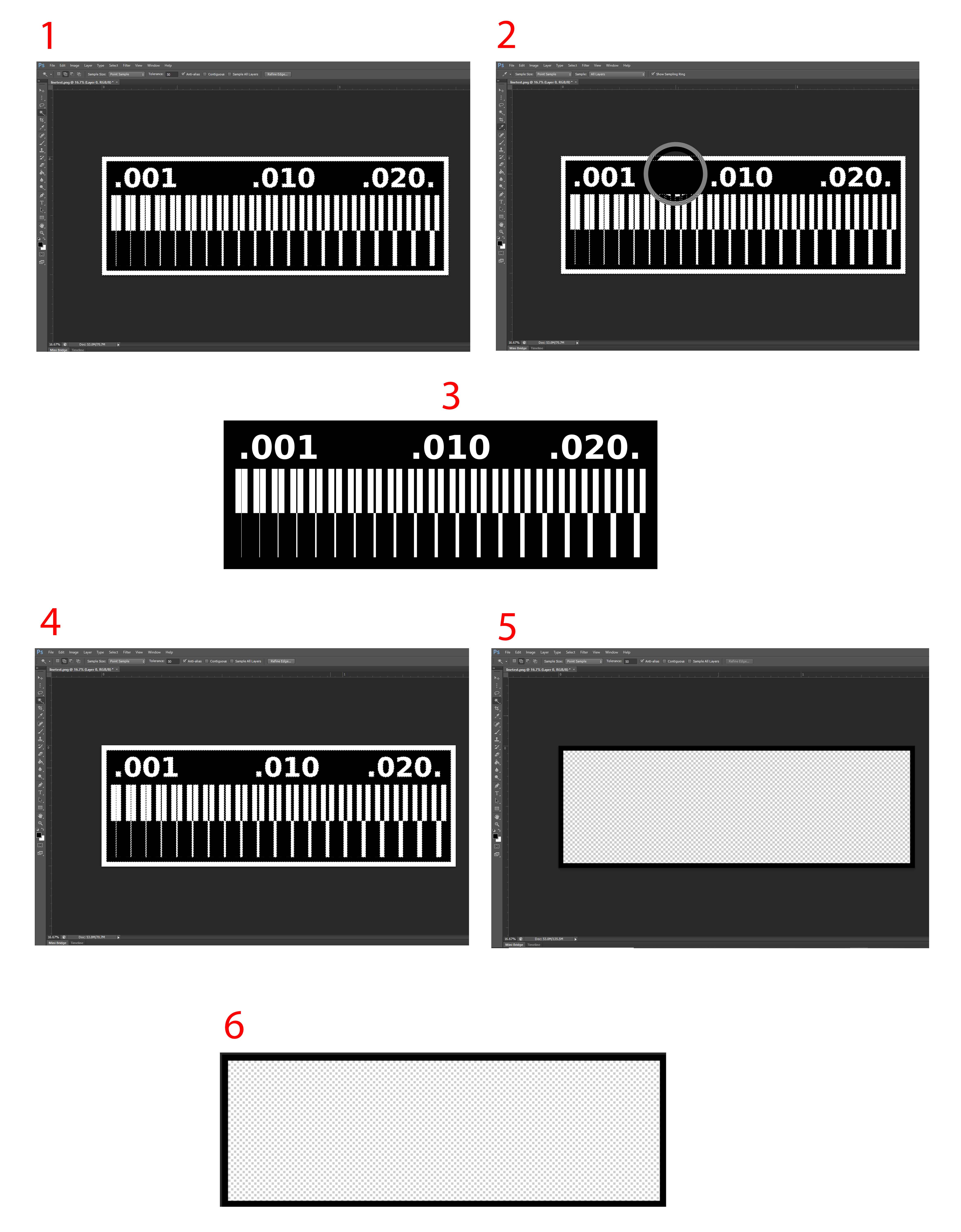

Next we generated the g-code for each of the images. We used FabModules.org to generate our g.code.as shown in the steps below.
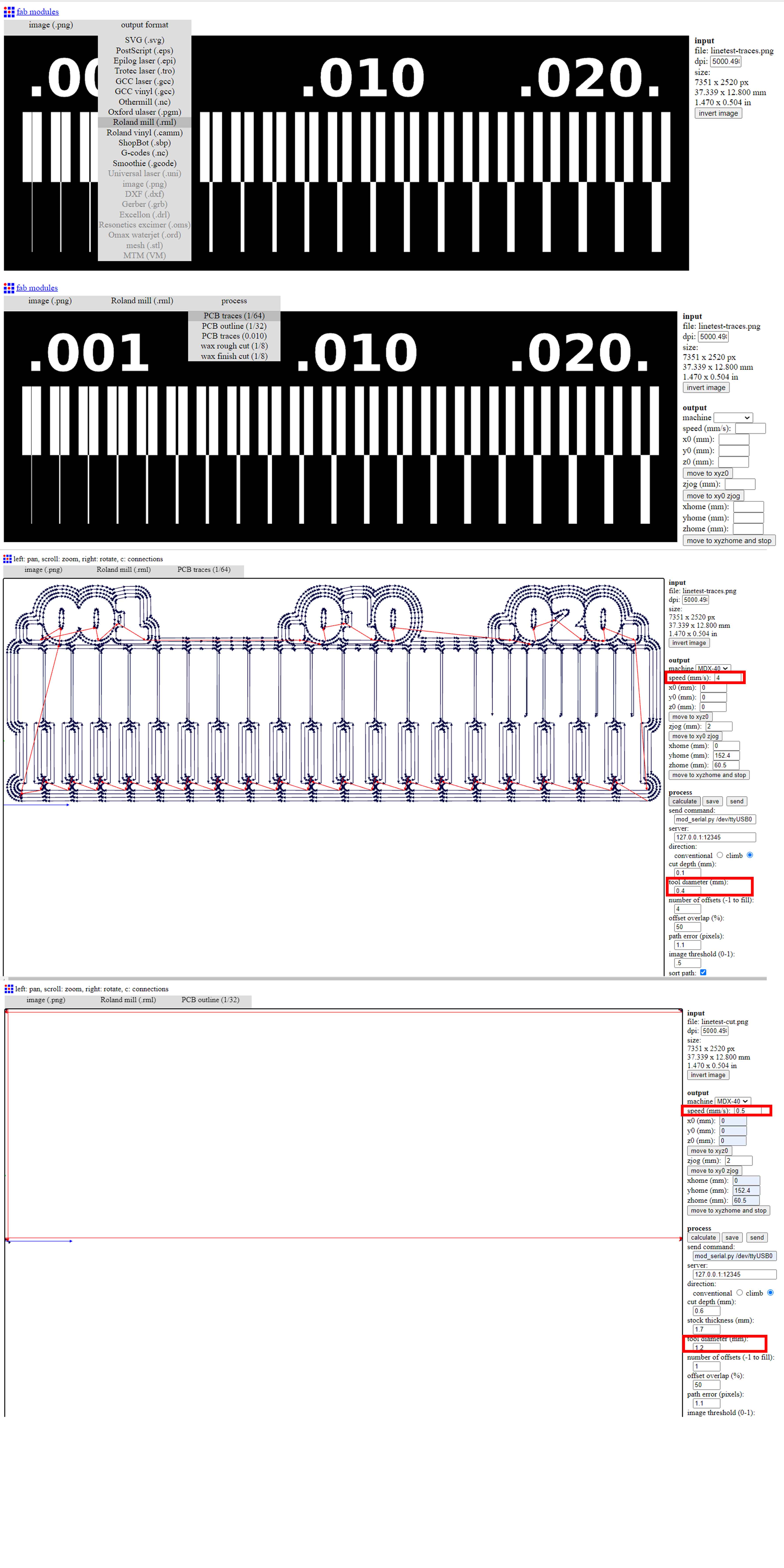
Settings that we changed for the inner lines:
Settings that we changed for the outer lines:
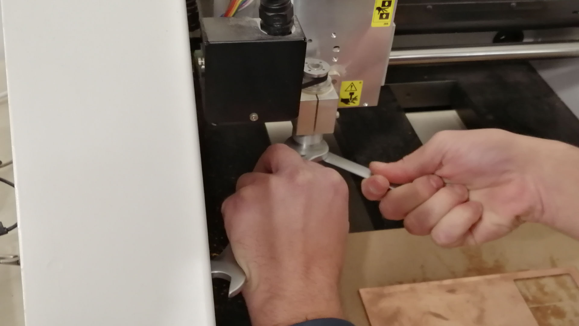
Now that we have our files ready, it is time to go to the machine, turn ON the machine by pressing “power” button and wait for it to initialize, then press “view” to move the machine to the initial origin. Grab the 0.4mm bit that we will use for traces, Insert the router bit into the collet. Retract the router bit by 4 mm or so, and then hand-tighten the collet nut to hold the bit in place. Fully tighten the collet nut with the appropriate wrench
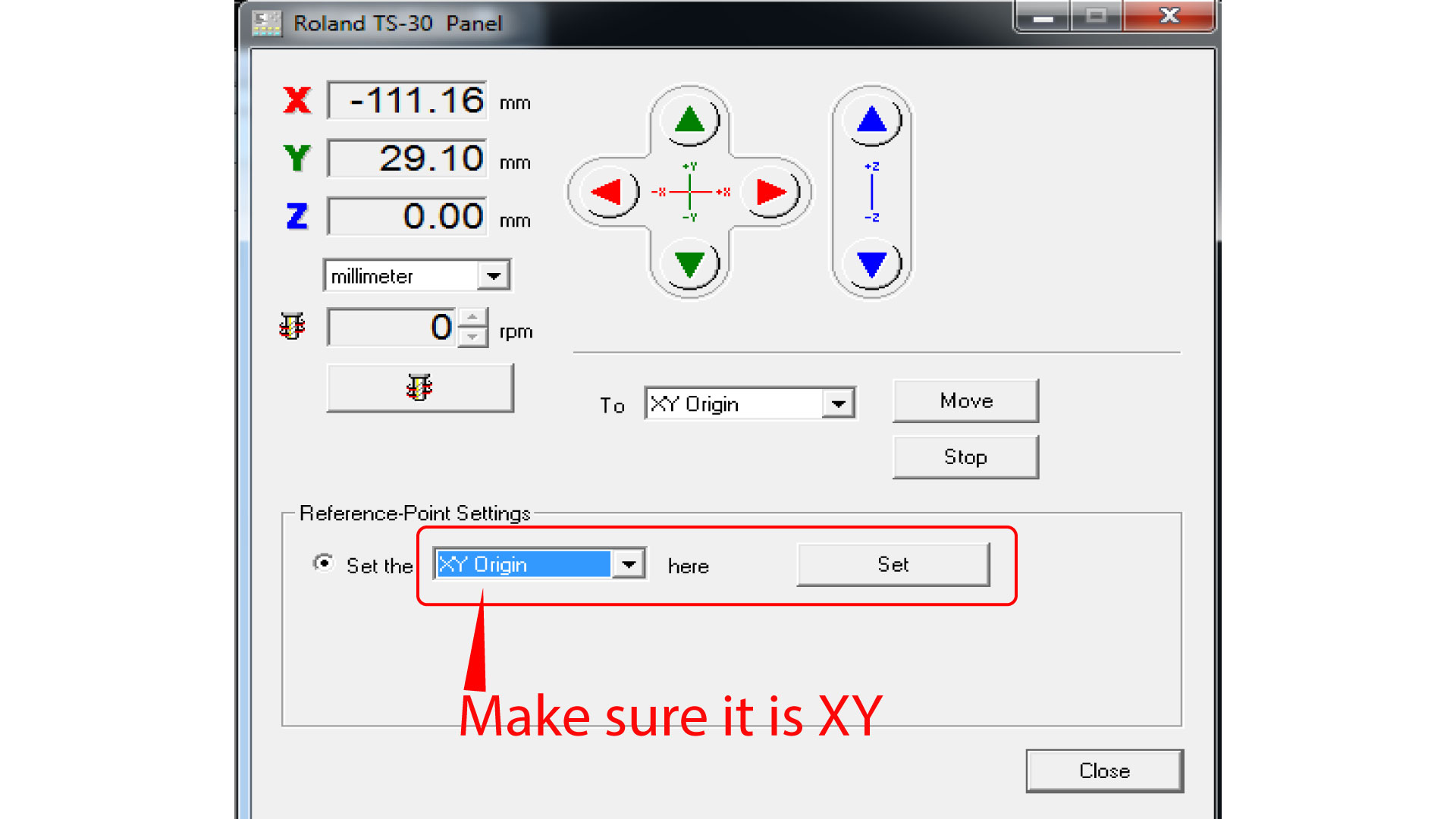
Next, we move to the PC, open the software “DropOut”, at this stage we want to first zero our XY axis from the software, and Z axis from the machines control panel. Go to “File > Print set up > Properties > Options > Operation panel”. Before moving the XYZ, press “view” on the machine to get it out of the “view” position, now in the operation panel, move the XY axis into your desired starting point, note that the starting point in the generated G-code is bottom-left corner. Then press set XY origin.
After that we want to zero the Z-axis, to do that, we need a digital multimeter, and an alligator. Put the digital multimeter in buzzer mode and touch the negative and positive ends together to see if it is buzzing, then attach the alligator to one terminal of the multimeter, attach the other end of the alligator to the router bit. Now we want to lower the our Z until it touches the copper board, do not forget to touch the free side of the multimeter with the copper board so when the bit touches the copper the multimeter would beep. Press the down arrow on the machine until it gets close to the board “be careful not to go down too much and break the bit”, then go slowly until the multimeter buzzes, when it does, press the down arrow three little pushes to make sure we have our Z-axis ready.

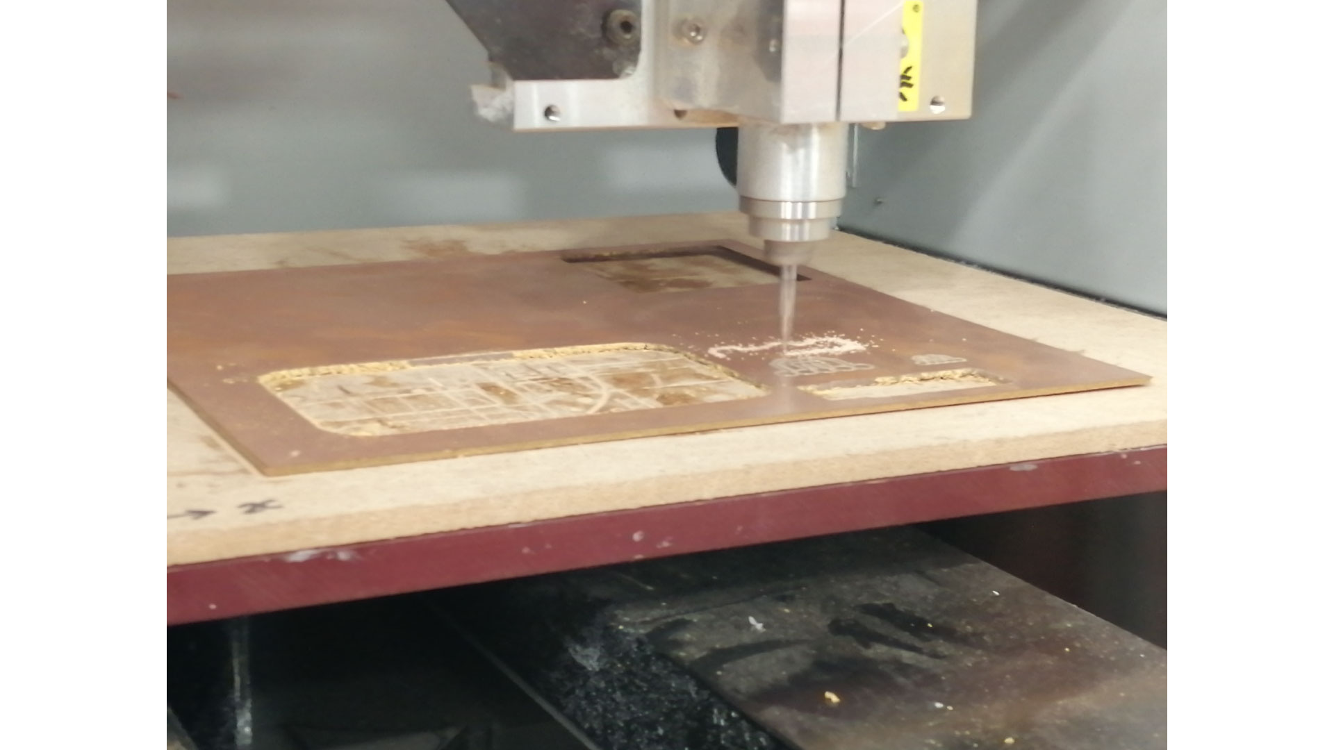
We then opened the software, and in the properties we go to tools, and we select the spindle RPM as 10,000. Then we go to the first window in the software, and we add our traces G-code that we generated previously. Now that we are ready to start the job, press “Output” on the software, the machine should start milling now, do not open the door of the machine unless there is an emergency. When the job is done, wait a minute for the machine to stop, then hit “view”, when the XY goes to the corner, open the door, and use the vacuum cleaner to clear the dust.
Now we want to cut our outline, to do so, we need to change the bit following the same previous steps, just make sure the bit does not fall down when removing it. we used a 1.2mm bit to cut our outline. After putting the new bit, we need to zero the Z-axis again, we will not use the multimeter this time. Place a paper on the copper board, and carefully move down until the bit touches the paper and makes it hard to move sideways.
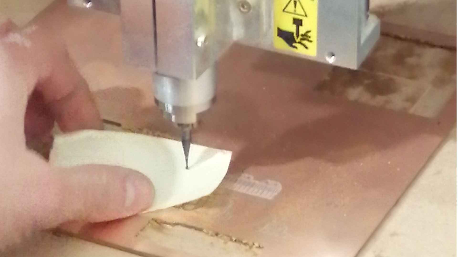
Finally, now that we have our new Z position, we will go to the software, delete the old G-code, and add the outline G-code, then press “Output”, the job should now start. When the job is over, clean the dust, then carefully remove the PCB with by pinching it from the side with a screwdriver. Then, remove the double sided tape that is on the back of the PCB
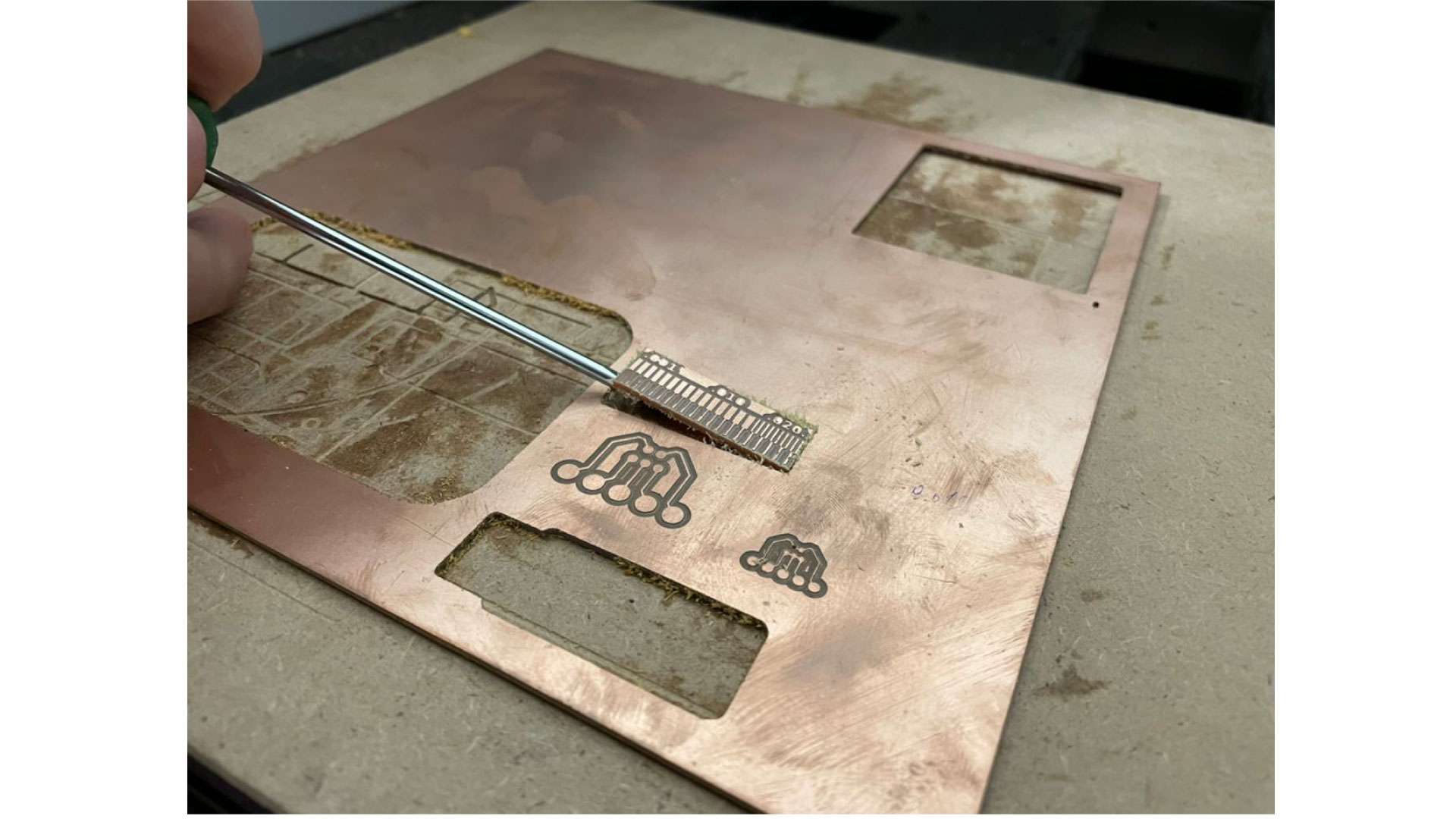
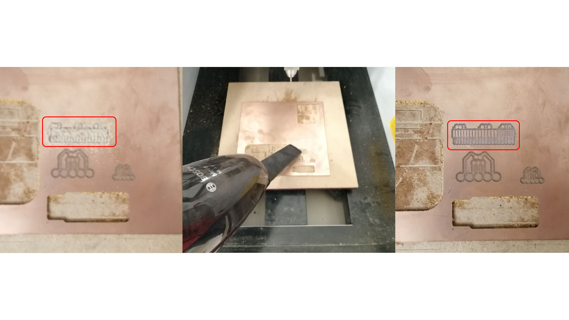
We noticed that the results are note very satisfactory, but they do the job.
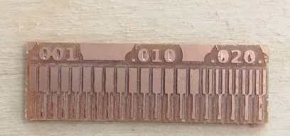
Concerning the clearance between the paths, we noticed that the used bit of diamter 0.4 mm, does not allow us to mill between the path for a width less than 0.384mm.
Concerning the line size, we noticed that the milling bit can mill line of tiny thickness of a minumum 0.005'' (0.13mm). Thinner line were missing in the test. Thus we deduced that we cannot do traces less than 0.13 mm with our bit.