Welcome to Berytech Fab Lab

So the objective of the sixth week is to discover how to design and produce a microcontroller circuit board.
Group Assinment
The group assginment was to use the test equipment in our lab to observe the operation of a microcontroller circuit board.
A microcontroller (MCU for microcontroller unit, or UC for μ-controller) is a small computer on a single integrated circuit. In modern terminology, it is similar to, but less sophisticated than, a system on a chip (SoC); an SoC may include a microcontroller as one of its components. A microcontroller contains one or more CPUs (processor cores) along with memory and programmable input/output peripherals.
The main machine used in this week's assignment are the following
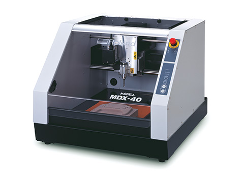
- Roland MDX-40 is the Desktop CNC machine used to mill copper boards.
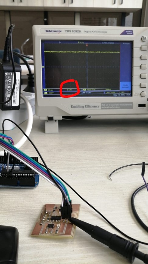
- Tektonix TBS 1052B is the oscilloscope used to observe the operation of the microcontroller circuit board.
- National Instruments VirtualBench was used as a digital oscilloscope to observe and document the operation of the microcontroller circuit board.
- FLUKE 179 was the multimeter used throughout all the process.
- ProsKit SS 207 was the soldering iron used for welding the components.
Observe the Operation of a Micro*-Contoller
The machine used: Roland MDX-40
We connected the Positive Probe of the Tektronix TBS1052B to on the Vcc of the board and the Negative Probe to the Gnd of the board and we read the 5v signal on the screen.
Testing SCK Pin
Here we connected the Positive Probe to the SCK Pin on the board and we read the signal while uploading the code.
Testing Blinking Led
Here we connected the Positive Probe to the LED on the board and we read the signal while the led is blinking:the code used is a simple blink code