Computer Controlled Cutting
So the objective of the third week is to discover the various equipment and technologies used for cutting digital designs into various material. There are many different Computer Controlled (CNC) machines available that are used for cutting into a wide range of material. However, we tested only two technologies in this assignment, the Laser Cutter and the Vinyl Cutter.
Group Assinment
The group assginment was to characterize the laser cutter we have in the lab and make test parts that vary in the cutting settings and dimensions.The students were supposed to characterize your lasercutter's focus, power, speed, rate,kerf, and joint clearance.
Numerical control (NC) (also computer numerical control (CNC)) is the automated control of machining tools (drills, boring tools, lathes) and 3D printers by means of a computer. An NC machine alters a blank piece of material (metal, plastic, wood, ceramic, or composite) to meet precise specifications by following programmed instructions and without a manual operator.
Machines Used
The main technologies used in this week's assignment are the Laser Cutter and the Vinyl Cutter.
The Laser Cutter is a machine that cuts material precisly based on a digital file by the help of a guided laser that burns, or vaporizes material.
- Epilog Fusion M2 120 Watts was used for laser engraving and laser cutting in this assignment. This Epilog Fusion M2 uses the CO2 Laser Technology to cut and engrave. The laser source is guidged by 2 axis (X and Y) that guide the focal point of the laser where cutting will occur.
- Universal Laser Systems ILS9.150D 75 Watts was used for laser engraving and laser cutting in this assignment. This Universal Laser Systems ILS9.150D uses the CO2 Laser Technology to cut and engrave. The laser source is guidged by 2 axis (X and Y) that guide the focal point of the laser where cutting will occur.
The Vinyl Cutters were used this week for the Individual Assignments. The Vinyl cutter is a CNC machine that controls a blade that cuts into different soft material, based on a digital design.
Characterize the lasercutter and making test parts
Two different machines were charectrised this week. Every student worked on charecterising one of the machines.
The machine tested by Issa: Laser Cutter – Epilog Fusion M2
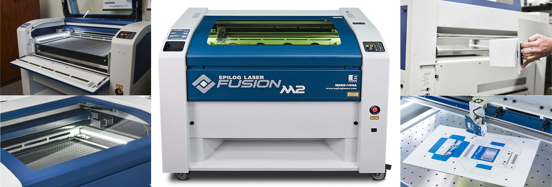
- Work area: 500mm x 800mm
- Materials: wood (12mm), glass, cork, leather, cardboard, paper, fabrics, non-PVC acrylics, and other organic materials (up to 13mm)
- File type: AutoCad .DXF, .CDR, .EPS, JPG, and BMP for raster.
- Power: 120 Watts
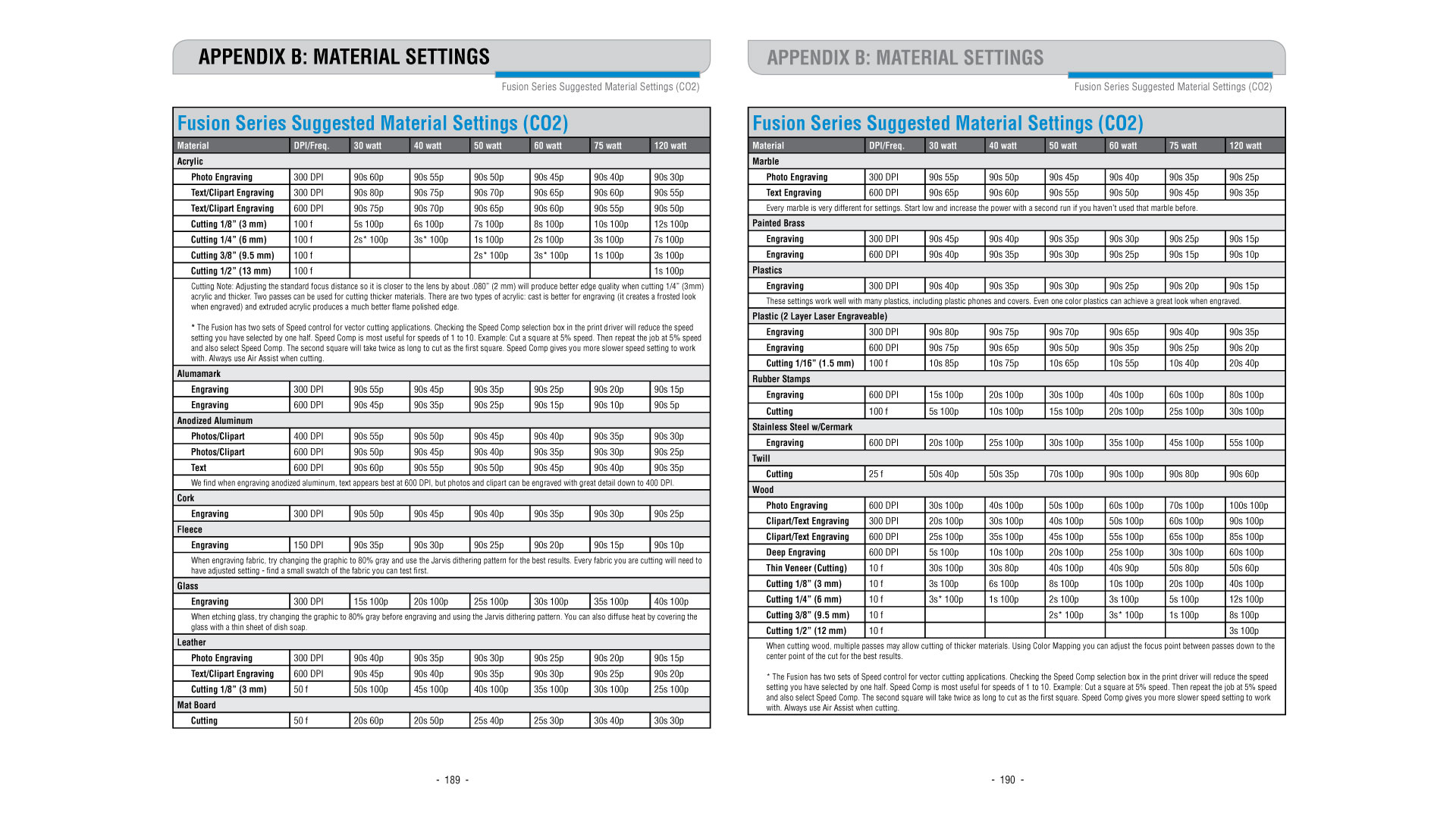
Fusion Series Suggested Material settings for Power, Frequency and Speed:
First test: Cutting Test
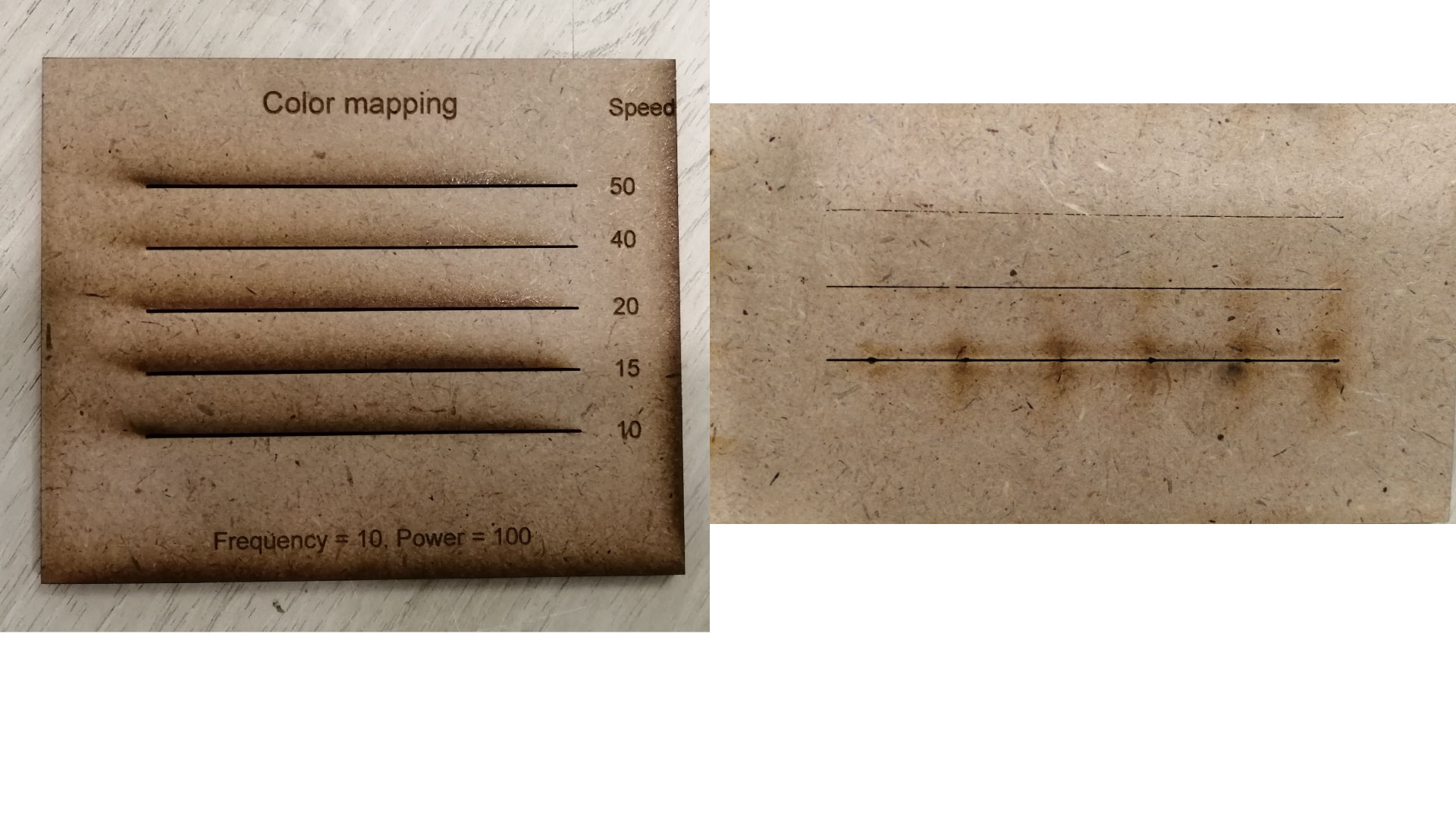
- Objective: Select the best cutting settings for a specific material in terms of POWER, FREQUENCY, and SPEED . In the case of wood, the FREQUENCY should be the lowest (10).Cutting SPEED needs to be determined in order to have the smallest kerf.
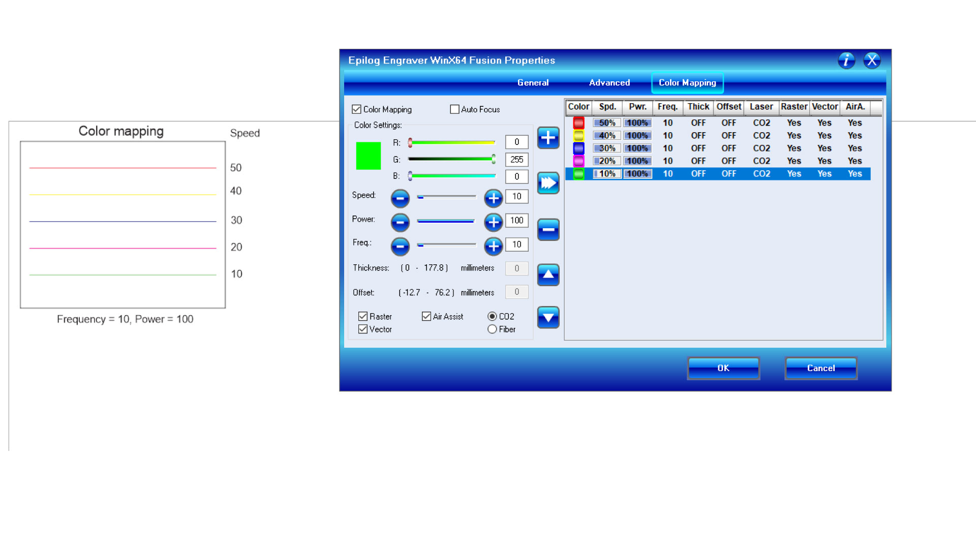
- Method: Cut multiple lines with different SPEED settings around the reference speed provided by the manufacturer’s specifications. Observe by eye at which speed the material is fully cut. We used color mapping to cut different lines with different speed settings. The first fully cut line should be the finest cut, thus the smallest kerf.
- Material Used: MDF 3.5mm
- Results: According to the above test the best settings are power 100% and speed 8%.
Second test: Kerf Test
- Objective: Measure the kerf for the setting previously selected
- Method: Cut one or multiple segments with the same setting. Measure the length of the outer frame, measure the length of the adjacent cut segments, divide the difference by the number of cuts. (A-B/number of cuts) The result is an estimation of the kerf. We made two tests with different layouts to get an average.
- Material Used: MDF 3.5mm
- Results: Using the settings speed 8% power 100%
- Test I:(100.3 – 98.65)/11 =0.15
- Test II:(50.10-49.80)/2= 0.15
Third test: Fitting Test
- Objective: Testing different dimensions to discover best dimensions for a press fit kit
- Method: Design parts with slots of variable dimensions, to test which slot is the best for your design
- Material Used: MDF 3.5mm
- Results: After doing the test, it showed that the 3.4mm joint was good but not too secure, and the 3.3 mm joint was too tight, so it must be in between.
The machine tested by Ghinwa: Laser Cutter – Universal Laser Systems ILS9.150D
- Work area: 900mm x 600mm
- Materials: acrylics, cardboard, soft wood (ex balsa), hard wood for engraving, textile, fabric, foams and many others.
- File type: .dwg, .dxf (AutoCAD), .ai (Adobe Illustrator) and jpg for raster images.
- Power: 75 Watts
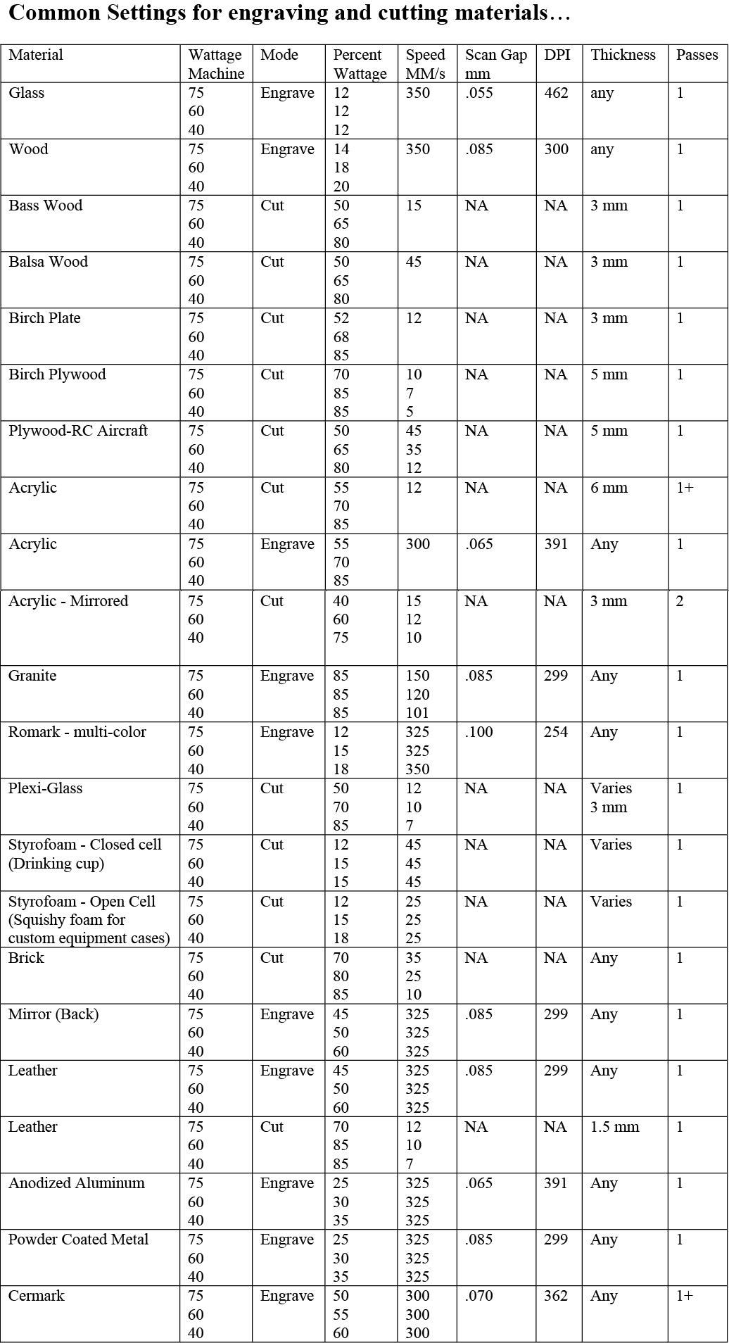
Universal Suggested Material settings for Power, Frequency and Speed:
First test: Cutting Test
- Objective: Select the best cutting settings for a specific material in terms of POWER, FREQUENCY, and SPEED . In the case of wood, the FREQUENCY should be the lowest (10).Cutting SPEED needs to be determined in order to have the smallest kerf.
- Method: Cut multiple lines with different SPEED settings around the reference speed provided by the manufacturer’s specifications. Observe by eye at which speed the material is fully cut. The first fully cut line should be the finest cut, thus the smallest kerf.
- Material Used: MDF 4mm
- Results: According to the above test the best settings are power 100% and speed 8%.
Second test: Kerf Test
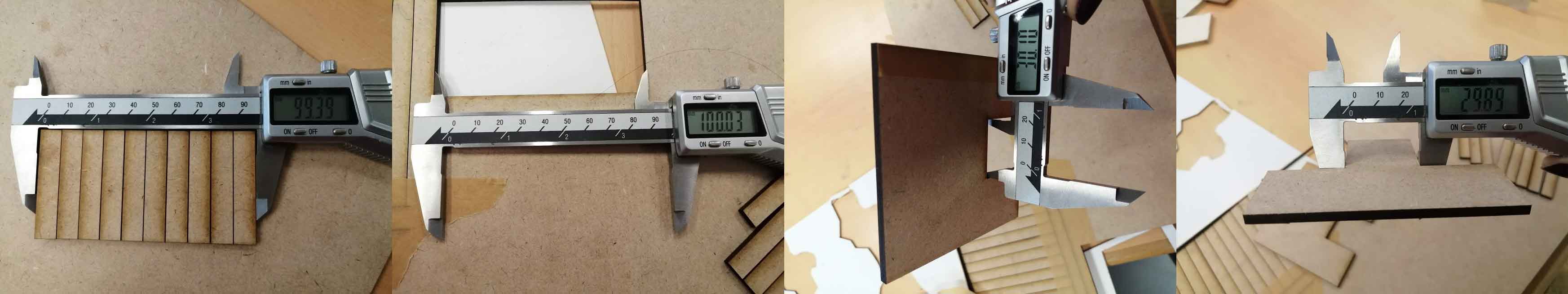
- Objective: Measure the kerf for the setting previously selected
- Method: Cut one or multiple segments with the same setting. Measure the length of the outer frame, measure the length of the adjacent cut segments, divide the difference by the number of cuts. (A-B/number of cuts) The result is an estimation of the kerf. We made two tests with different layouts to get an average.
- Material Used: MDF 4mm
- Results: Using the settings speed 8% power 100%
- Test I:(100.03-99.39)/11=0.05
- Test II:(30.10-29.89)/2=0.10
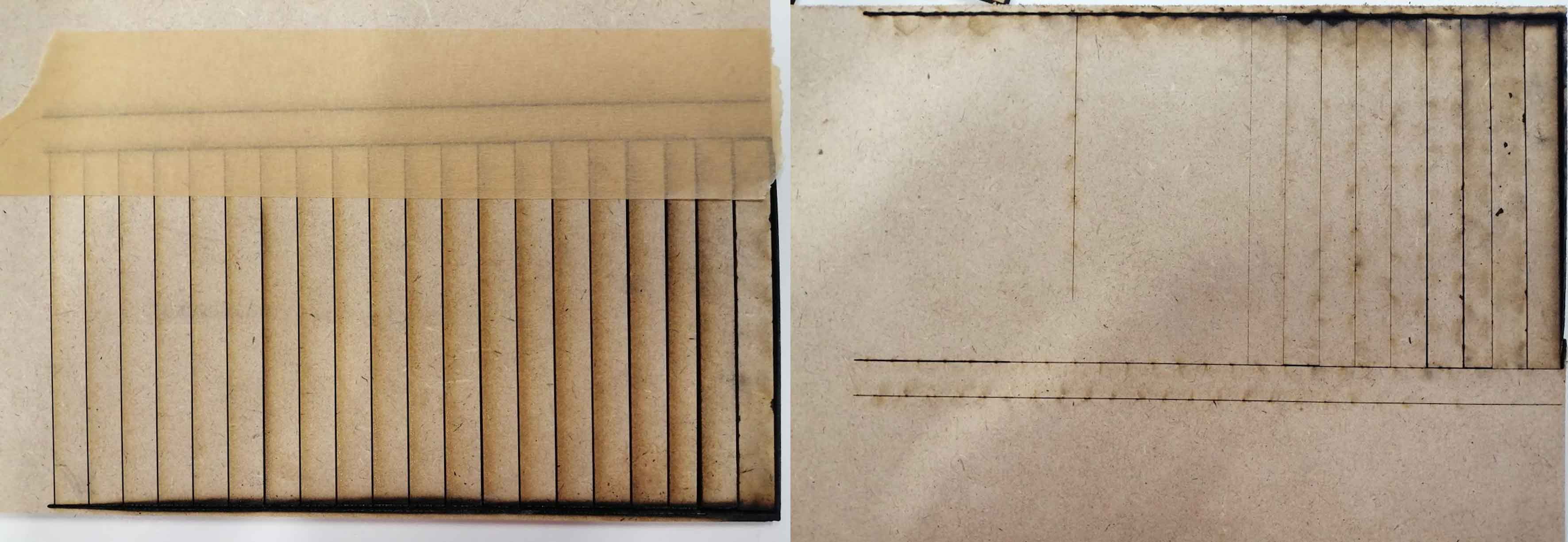
Third test: Living Hinges
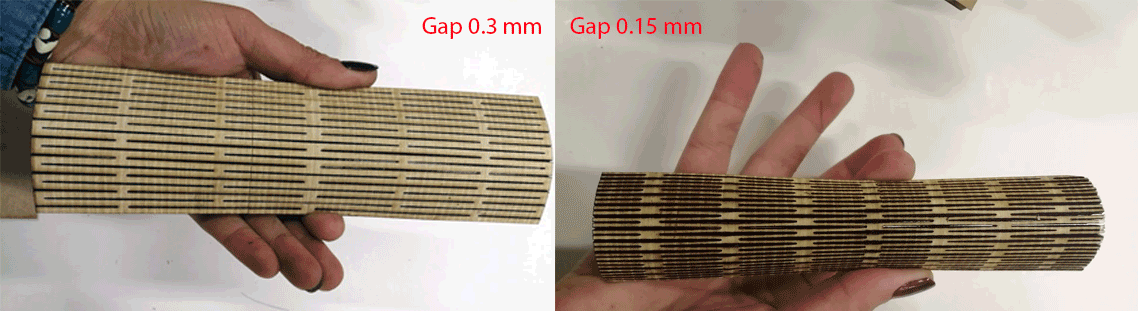
- Objective: Testing Living Hinges
- Method: Using Inkscape software and the extension Living Hinge I drew a file to cut and experiment on the laser machine. Two different options gap 3 mm and 1.5 mm were tested
- Material Used: MDF 4mm
- Results: Results are shown in the image above
Forth test: Engraving Test
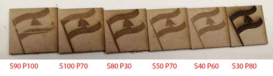
- Objective: Testing different Raster Setting for Image Laser Engraving
- Method: Engrave a picture using various settings to visualize the resuls.
- Material Used: MDF 4mm
- Results: Results are shown in the image above
