Computer Controlled Machining
So the objective of this week is to get introduced to Computer Controlled Machining and to learn how to use and operate the big CNC machine, mainly the one used to produce big parts.
CNC Machining is the process used in the manufacturing sector that involves the use of computers to control machine tools. Those tools include lathes, mills, routers and grinders.
In this section, we will learn on how to operate the CNC Router Machines.
Group Assinment
The group assginment was to characterize the specifications of our PCB production process.
Computer numerical control (CNC) is a method for automating control of machine tools through the use of software embedded in a microcomputer attached to the tool. It is commonly used in manufacturing for machining metal and plastic parts.
Machines Used
The main machines used in this week's assignment is the CNC Milling Machine
- The Shopbot 96-60-8 is the main CNC Router available in our lab, having the largest size. It has a working volume of 2.44m x 1.52m x 0.15m.
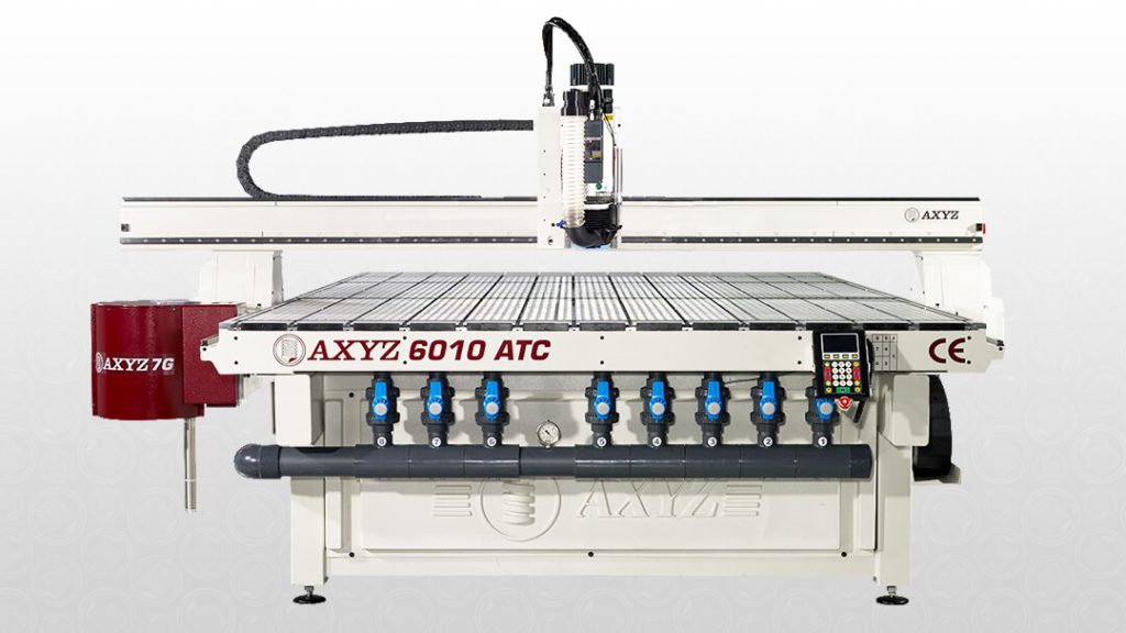
- The AXYZ CNC Machine is the main CNC Router available in the ARDTech lab, having the largest size. It has a working volume of 2.44m x 1.52m x 0.15m.
Below are the things we have to understand when using a CNC Milling machine:
- The Tool
- The Feeds and Speeds
- The Toolpath
1-The Tool
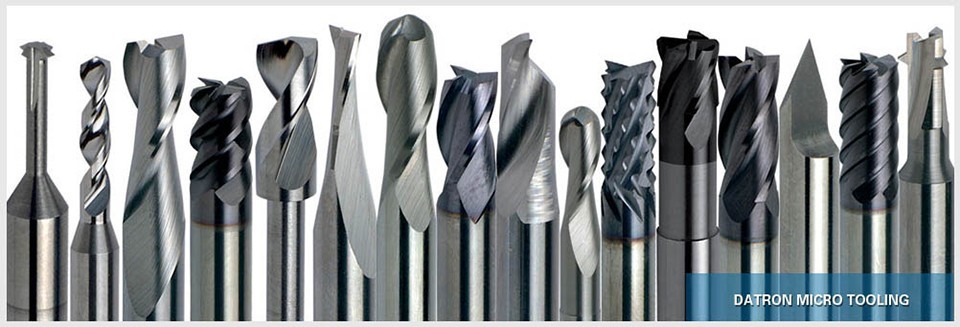
There are different tools that are used during the Machining process, each having a specified job.
The main types available are:
- Drill Bits are designed to plunge directly into material, cutting axially, and creating cylindrical holes
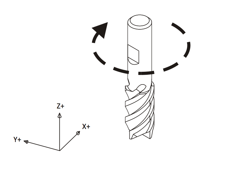
- End Mill Bits are designed to undergo horizontal carving and cutting laterally.
Each Bit has it own properties and the most important thing to look for is the Diameter, the Tooth the Flute, and the Cut Direction.
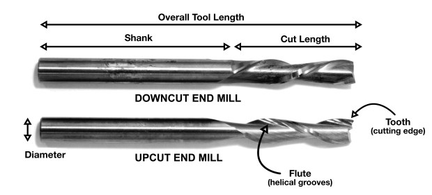
The Diameter describes the width of the cut made by the end mill.
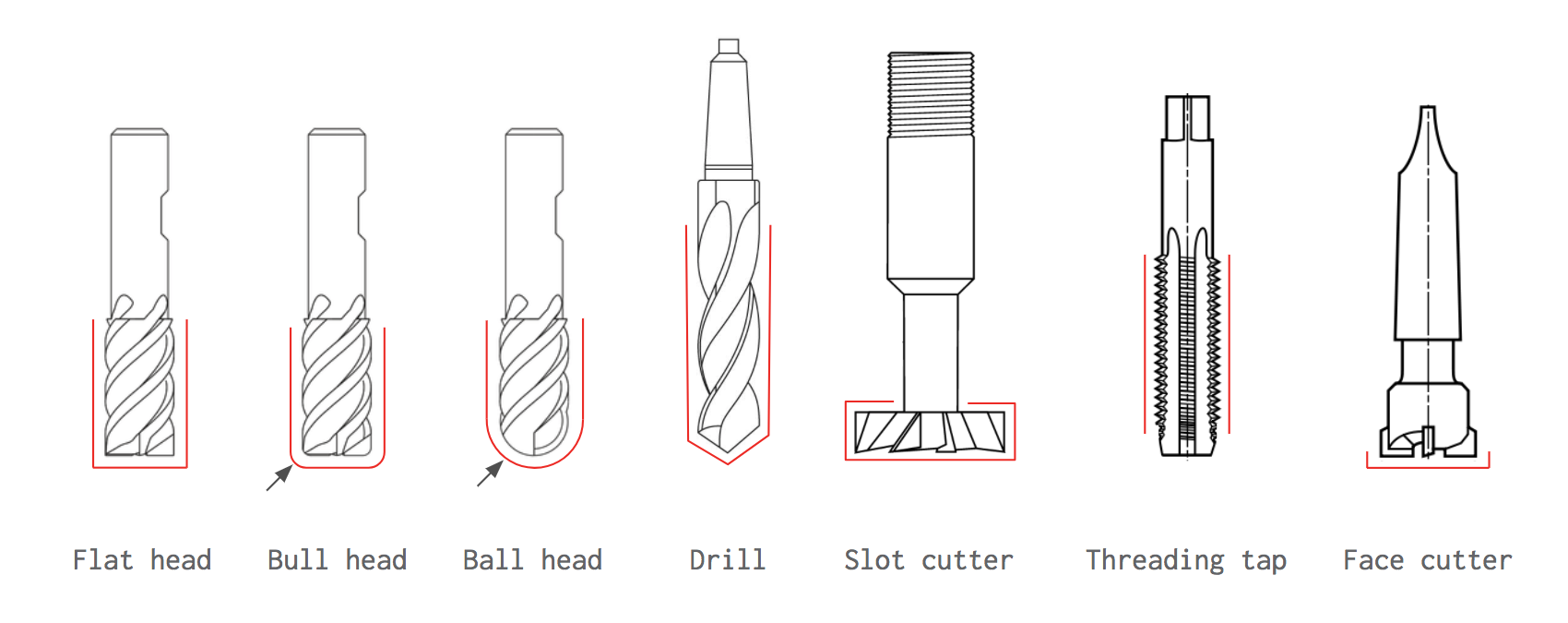
The Tooth is the tip shape (or head), there is different type of shapes designed for a particular purpose
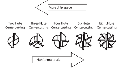
The Flute is the sharp edge of the end mill and each milling Bit has a certain number of flutes
The Cut Direction and rotation
And finally each bit has a chip load chart
Chip Load or Feed Per Tooth is the theoretical length of material that is fed into each cutting edge as it moves through the work material. This is simply the thickness of a chip which is formed during the machining of material. Chipload is important because the proper size chip will carry away heat, promoting long tool life. When the chip is too small, heat is transferred to the cutting tool causing premature bit failure. Too high of a chipload will cause poor edge finish, and transfer cutting load or thrust to the part, possibly causing it to move. A bit in good condition and running at recommended loads will be at room temperature when a cut is finished.
More flutes create a smoother surface finish, while fewer flutes remove material fastest, but make rougher cuts.
Proper chipload is important because chips dissipate heat. Hot cutters can lead to suboptimal results, including burned wood, a poor edge finish and dull tooling.
To summarize:
- More flutes create a smoother surface finish
- Fewer flutes are best at chip clearing, keep heat from building up
- Two or four flute cutters are the most common.
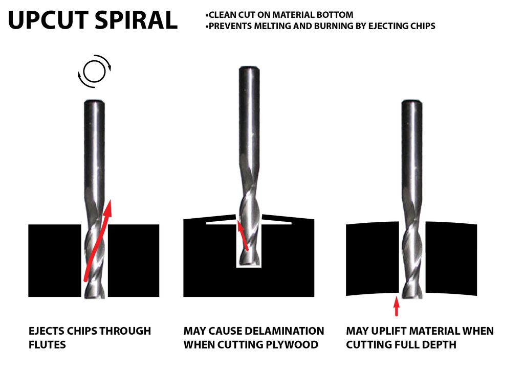
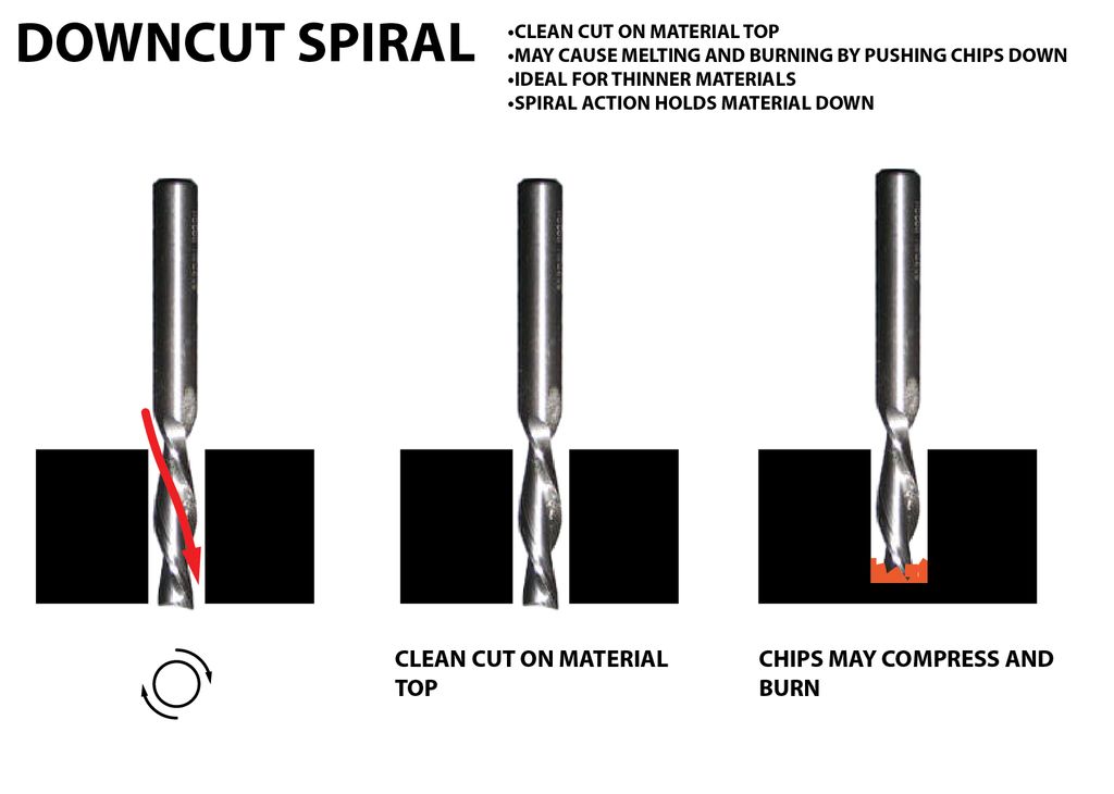
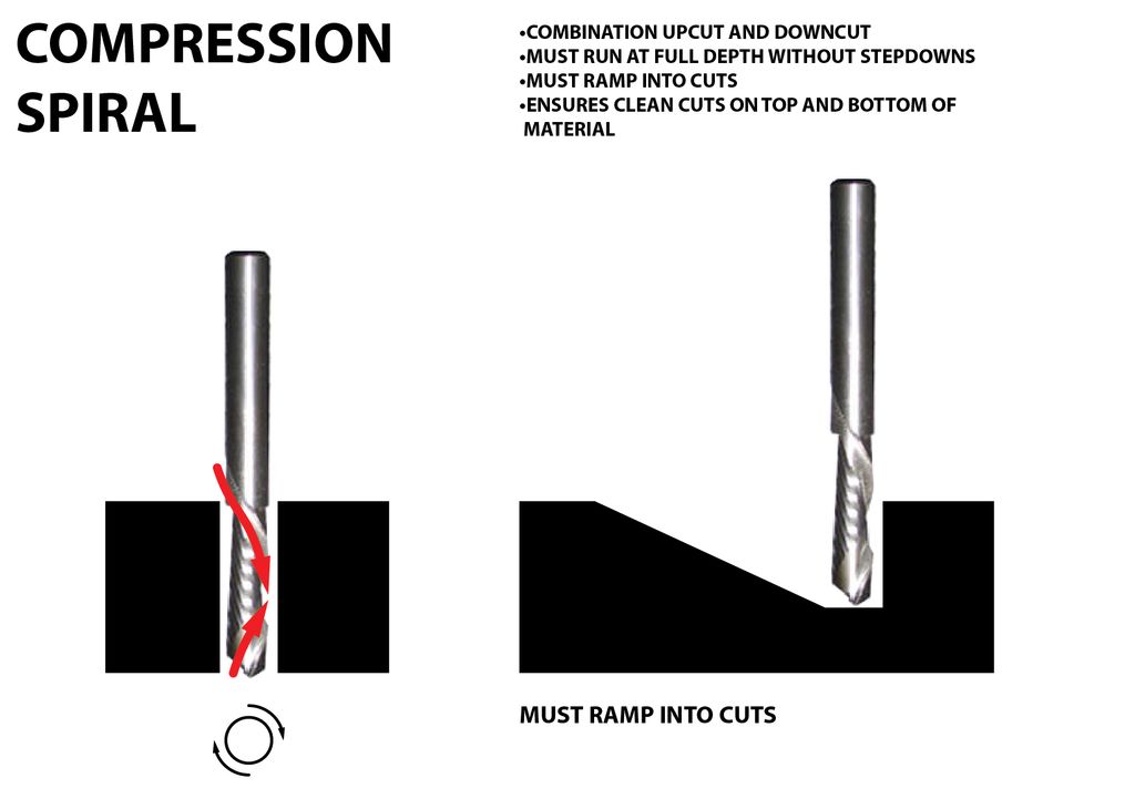
- The direction, size, speed and amount of chips being ejected can also damage the surface of the work piece. We can control how the tooling effects the material through our end mill type selection (upcut, downcut or compression) and speed at which we cut.
There are many tables that help you choose the chipload of the job you want to do, which will be needed to calculate the speed of the router. The image below represents one of the chip load charts available online.
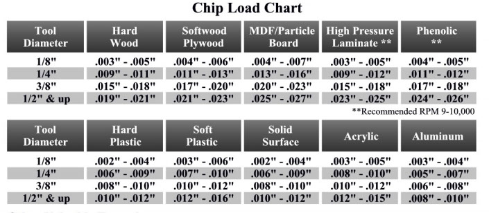
Please note that those represent a specific kind of milling bit. Specific loads for your tools can be obtained from your router bit manufacturer.
2-The Feeds and Speeds
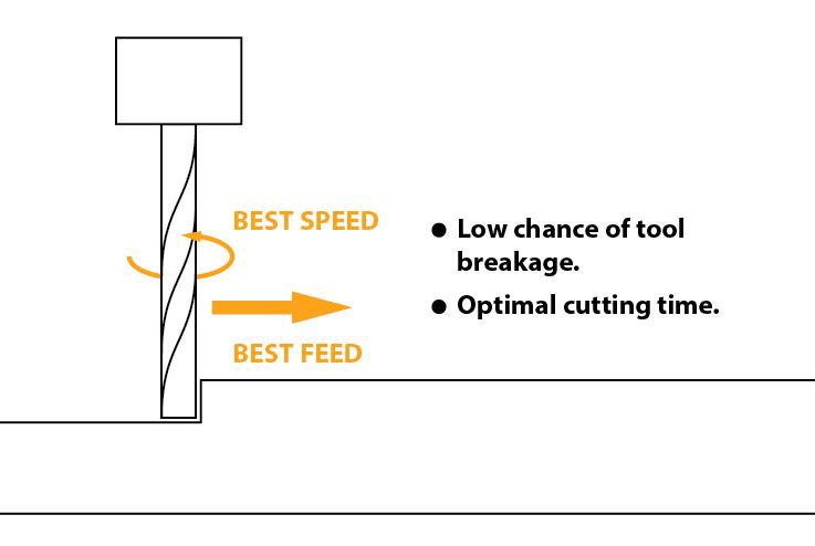
The speed at which we move a cutter across the material is called the “feed rate”. The rate of rotation is called the “speed” and is controlled by how fast the router or spindle turns the cutting tool. Both feed rate and spindle speed will vary based on the material being cut. A general rule of thumb is that you want to move the tool through the material as fast as possible, without sacrificing surface finish. The longer the tool rotates in any one place, the more heat that builds up. Heat is your enemy and can burn your material or radically decrease the life or your cutting tool.
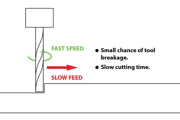
Feed rate vs spindle speed:Spindle speed that is too fast paired with a slow feed rate can result in burning or melting.
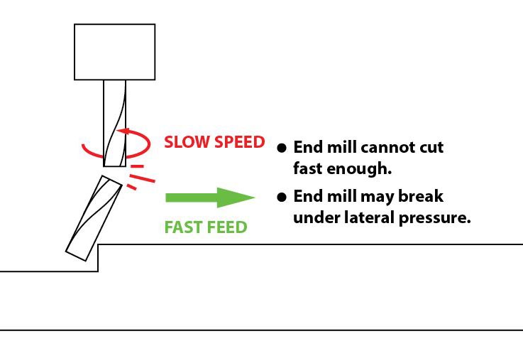
Spindle speed that is too slow paired with a faster feed rate can result in dulling of the cutting edge, deflection of the end mill and possibility of breaking the end mill.
A good strategy when selecting a cutter is to attempt to balance feed rate and spindle speed by performing two passes on the work piece. The first pass, called the roughing pass, can be done by using an end mill that will eject a large number of chips at a high feed rate. The second pass, called the finishing pass, then won’t require as aggressive of a cut and can provide a smoother finish at a high speed.
Chipload refers to the physical size of the chips the bit creates when making a cut.
Higher feeedrates produce larger chips.
Higher tool rpm produces smaller chips.
If your chips are to large, you risk breaking your bit.
If your chips are more like a fine powder, you are probably dulling your bit.
IT’s a balancing act but start with the manufacturers recommended settings and adjust from there.
Chipload = Feedrate / [RPM x number of flutes]
The nominal surface speeds used for various material are shown in the image below.

Here are some equations you need to know to calculate the spindle speed and the Feed Rate during any job in mind.
- Spindle Speed

- Feed Rate
Feed Rate = Spindle Speed (RPM)* Number of Flutes * Chip Load (inches) = Spindle Speed * Number of flutes * Chip Load = Answer inches/min
- Plunge Rate
Use a plunge rate of 50% or less of the feed rate.
3-The Toolpath
Many settings can control the toolpath of the tool. Among those settings are the following:
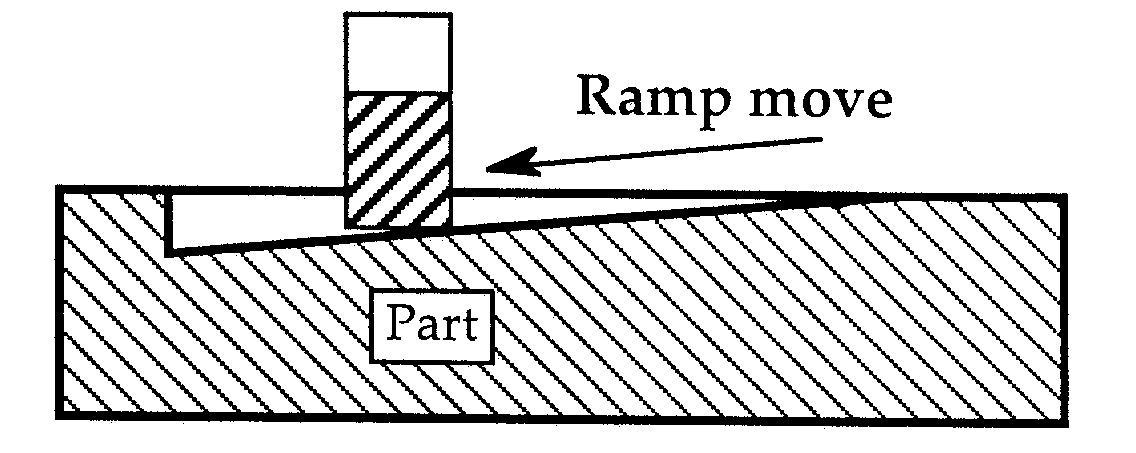
- Ramp is used to reduce the tool breakage and stress on the material being cut. It occurs by ramping the end mill slowly into lateral cuts, where your tool moves in an XZ or YZ 3D incline into your material to reduce stress on your bit when plunging.
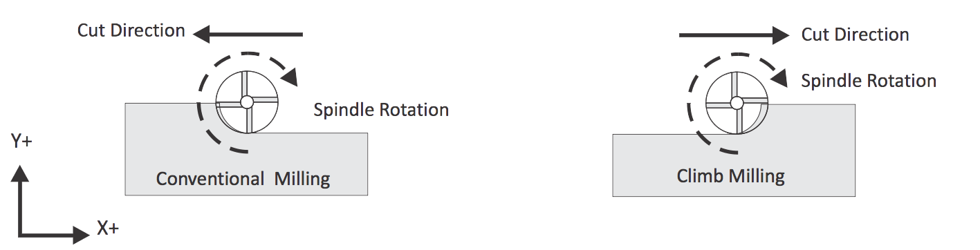
- Direction: there are two distinct ways to cut materials when milling: Conventional Milling (Up) and Climb Milling (Down). The difference between these two techniques is the relationship of the rotation of the cutter to the direction of feed. In Conventional Milling, the cutter rotates against the direction of the feed. During Climb Milling, the cutter rotates with the feed.
Characterize the CNC Milling Machine
The machine used for Test 1: Shopbot 96-60-8

- Software used for Test 1: V-Carve
- Material used is 10 mm MDF
- Tool used is 6 mm bits.
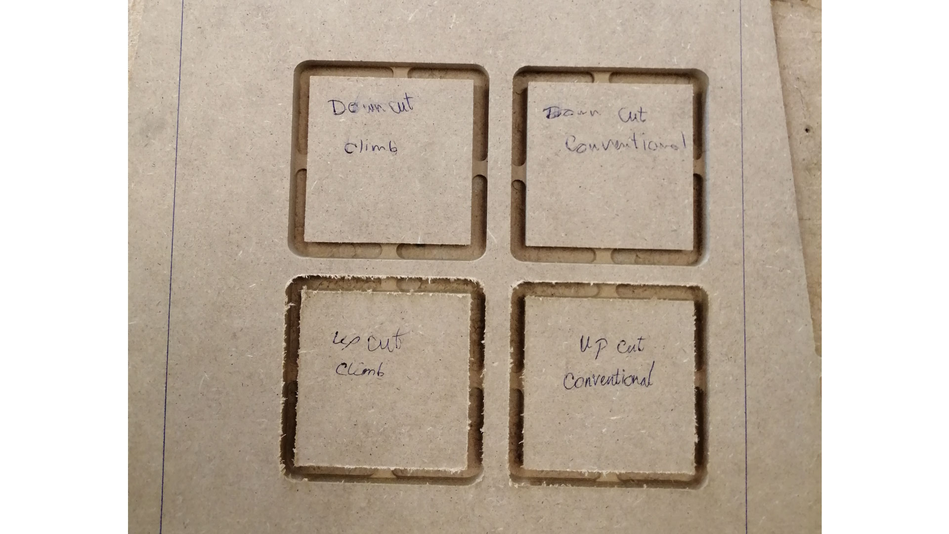
Test 1-A:
In this test, we used an up-cut 2-flute bit, and a down-cut 2-flute bit, and we tested both for conventional and climb paths.
We noticed that the down-cut bit had a smooth finish at the top, but the bottom had rough edges. The up-cut bit gave opposite results to the down-cut bit, with the bottom having the smoother edges. we have not noticed a difference between climb and conventional cutting for our test.
Test 1-B:
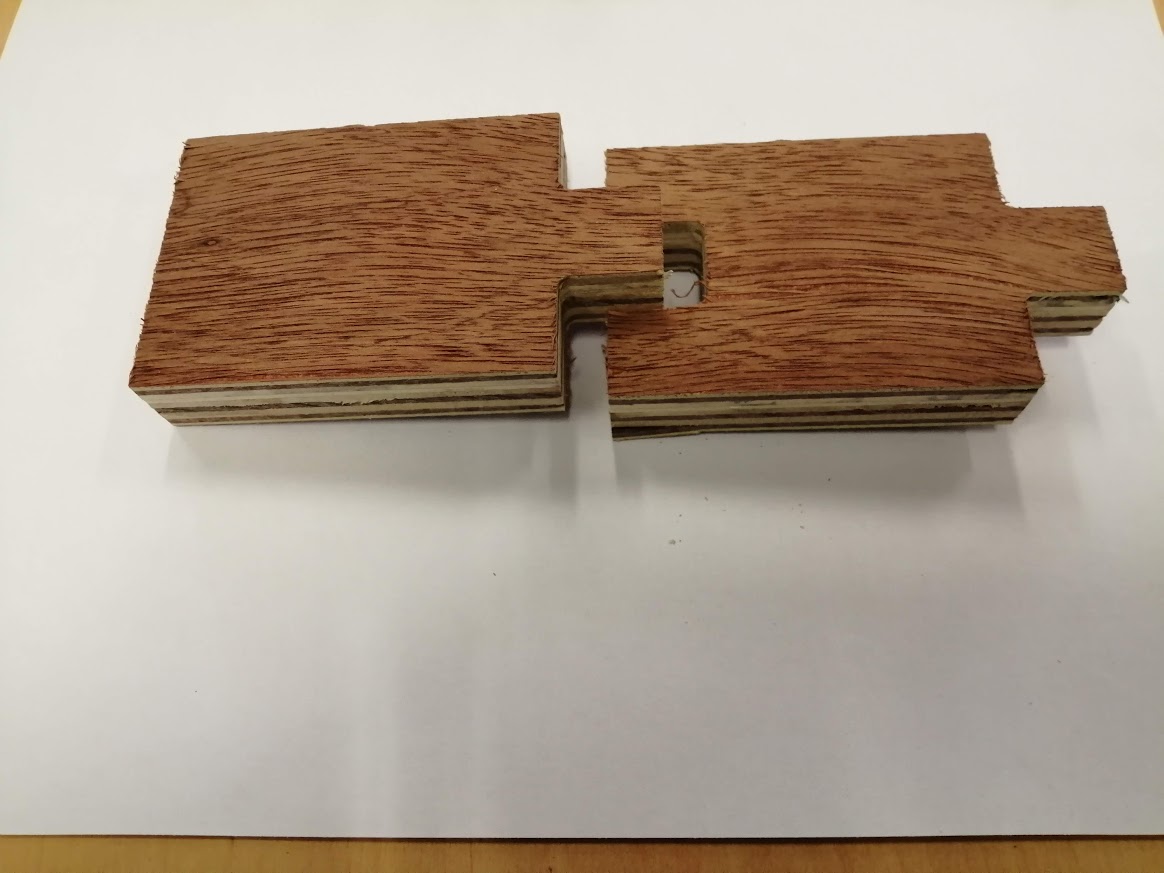
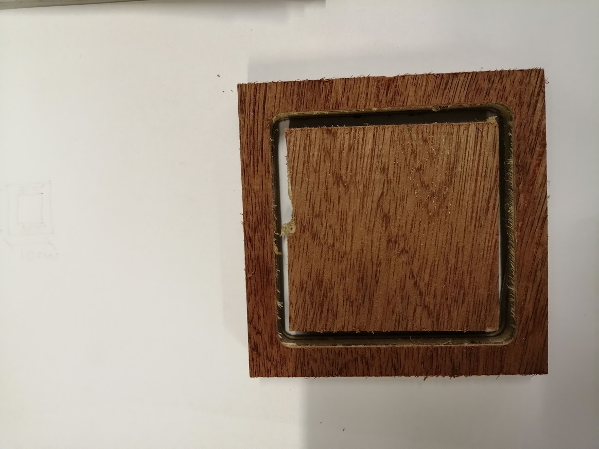
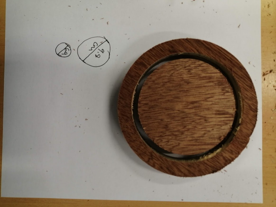
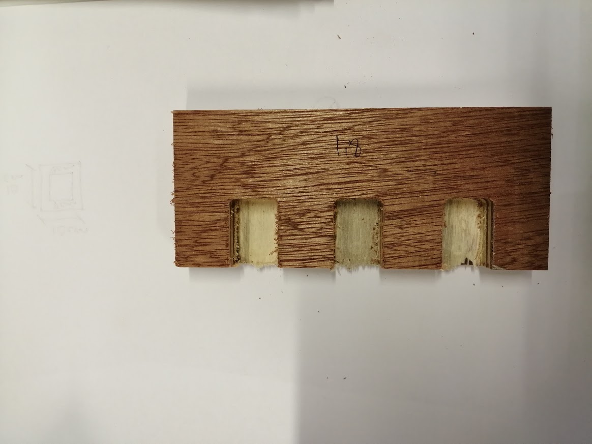
For the second test, we designed a 100mm x 100mm square, with a smaller (60x60) square inside of it, and a 100x100 circle with a smaller 60x60 inside. We measured the dimensions after cutting, the results for the square show that there is a 0.75mm difference in the X-direction, and a 0.4mm difference in the Y-direction. The results of the circle show that there is a 0.75mm difference for the outer circle, and a 0.34 mm difference for the inner one. We also tested T-bones with different depths, it is not possible to fit our piece in the slot without T-bones.
The machine used for Test 2: AXYZ
- Software used for Test 1: Rhino CAM
- Material used is 10 mm MDF
- Tool used is 6 mm bits.
Test 2-A:
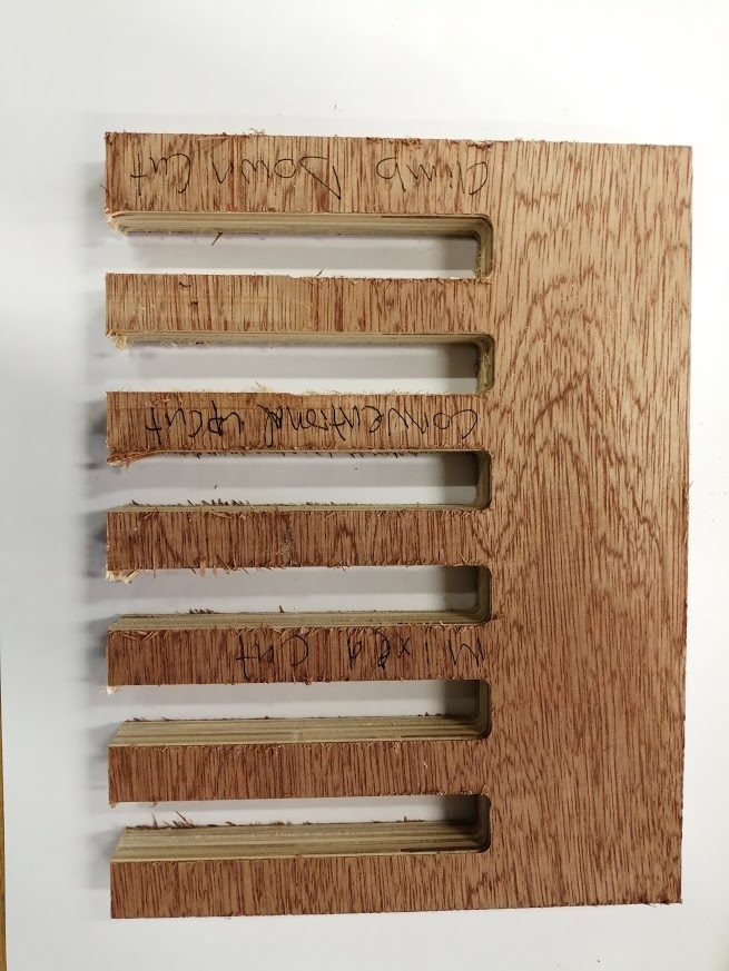
This test is to check different cutting directions found in RhiCAM the Climb toolpath Down cut Mill, Conventional toolpath Upcut Mill, and Mixed toolpath.
The results shows that the mixed cutting between climb and conventional has a better result than the other options.
The mixed option in RhinoCAM alternates the cutting direction between each parallel plane.
Test 2-B:
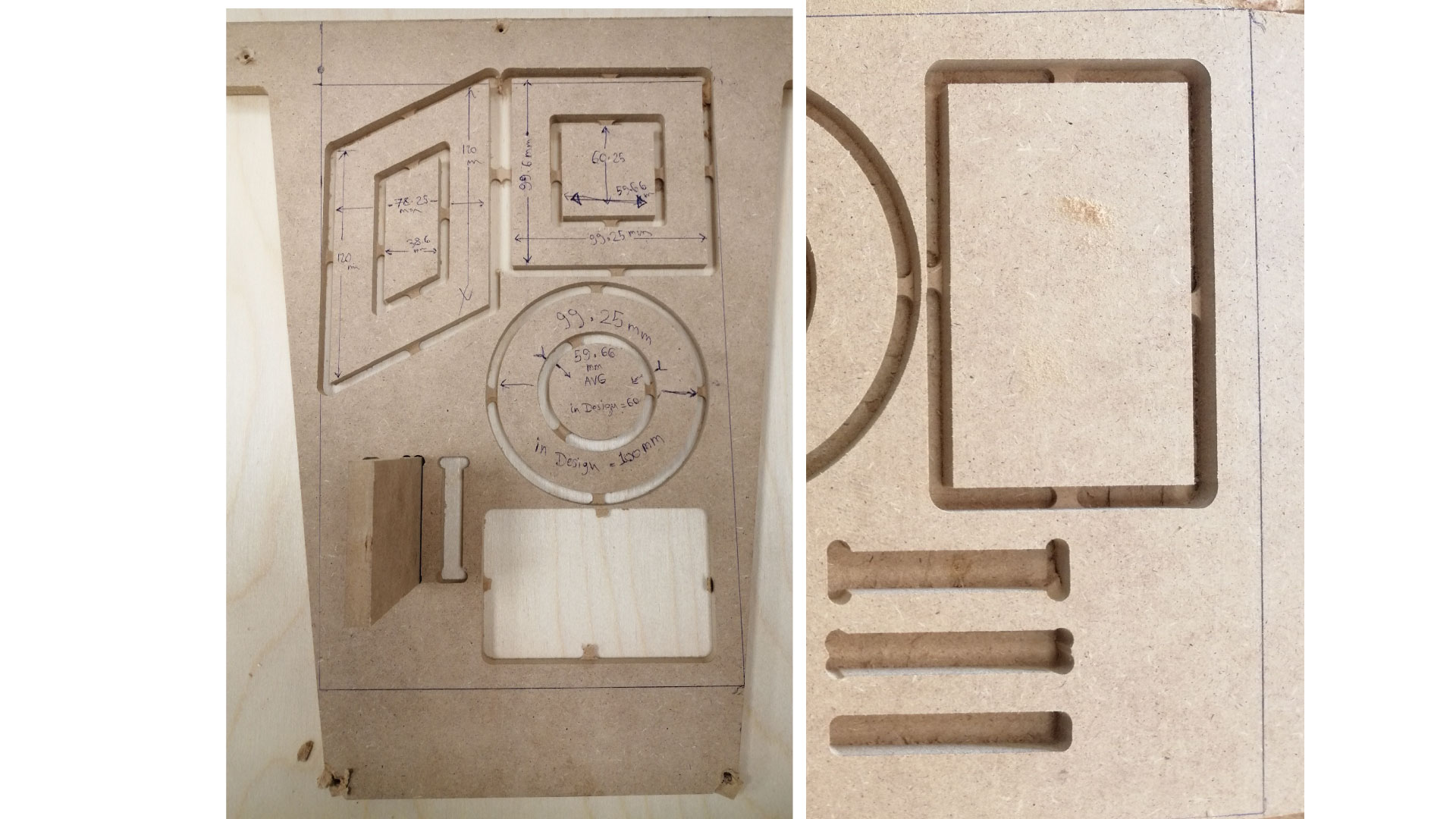
In this test we designed a 100 x 100 mm square, with a smaller square inside of it 70 x 70 mm, and a circle of diameter 100 mm with a smaller one inside of diameter 70 mm.
The results for the squares after cutting were the same dimensions and we didn't need to adjust anything in the file.
The result for the circles the 100 mm after cutting were 98 mm and the 70 mm were 69 mm.
As a result we need to increase the diameters by 1 or 2 mm.
Test 2-C:
In this test we tried the pocketing option the rectangles are 30 x 20 mm and after cutting the result was 28 x 18 mm.
As a result we need to increase the dimensions in the file 2 mm from each side to have perfect results.
In this test the openings are 20 x 20 mm and after cutting we had the same results but the joint didn’t fit so we need to increase the dimensions of one side by 1 or 2 mm.