GROUP ASIGNMENT: TEST EQUIPMENT
THE MULTIMETER
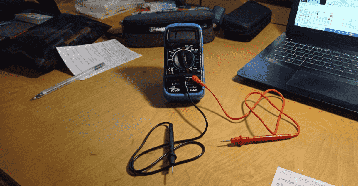
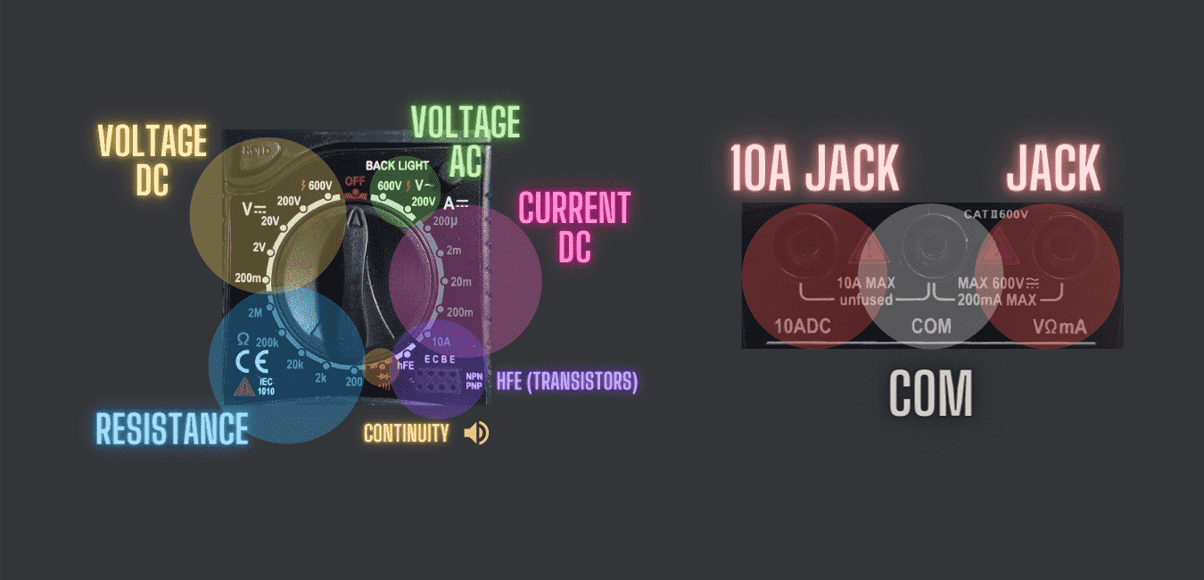
The multimeter, is the main test device that we have in the lab. this equipment is able to measure diferent electrical quantities,
as we can se in the following picture.
HOW TO MEASURE
1- the first thing that we need to know is what we want to measure:
- Voltage
- Current
- Resistance
- Continuty
2- Once we know which is the one that we want to measure, we have to set in the right position the wheel switch.
3- After that we have to place the leads on the right points of the circuit, to know which is the diference of the magnitude between both points.
4- Also, if we want to check the continuty of a PCB trace (for example), we have to place the lead betwen both points, and if it's connected we'll listent a beep.
Individual asignment
ELECTRONIC DESIGN
During this week we will have to design, produce and test our own Printed circuit, to achieve that mail stone we started learning about the main electronic components,
their properties, after that we get mor into microcontrolers, and finally the instructors sowed us KiCAD and Autodesk Eagle, two softwares used for electronics design
MAIN ELECTRONIC COMPONENTS:
The resistors are a kind of electronic component that implements electrical resistance in a circuit.
They are used mainly to reduce the current flow and divide voltages.
CAPACITORS
The capacitors are a kind of electronic component that stores a certain amount of electrical energy.
Ther are two kinds of capacitors:
- Ceramic: non polarized
- Electrolityc: polarized
DIODES
The Diodes are a kind of electronic component that only let the current flow in one direction.
The most used diodes are:
- ZENER
Is a kind of diode that let flow an small amount of current in the negative direction.
- SCHOTTKY
Is a kind of diode that is very eficien because the Voltage drop that produce is very small.
- LED
Is the Light Emition Diode used mainly to generate light signals.
OSCILATORS
The Oscilators are a kind of electronic component that Produces a periodic oscilating electronic signal.
TRANSISTORS
The Transistors are a kind of electronic component that close a circuit when it recive an small electrical current.
Is build with a semiconductor material, and it was very important to develop the modern electronics.
SIMULATOR
Also to test how this components works I used a Simulator: Flastad
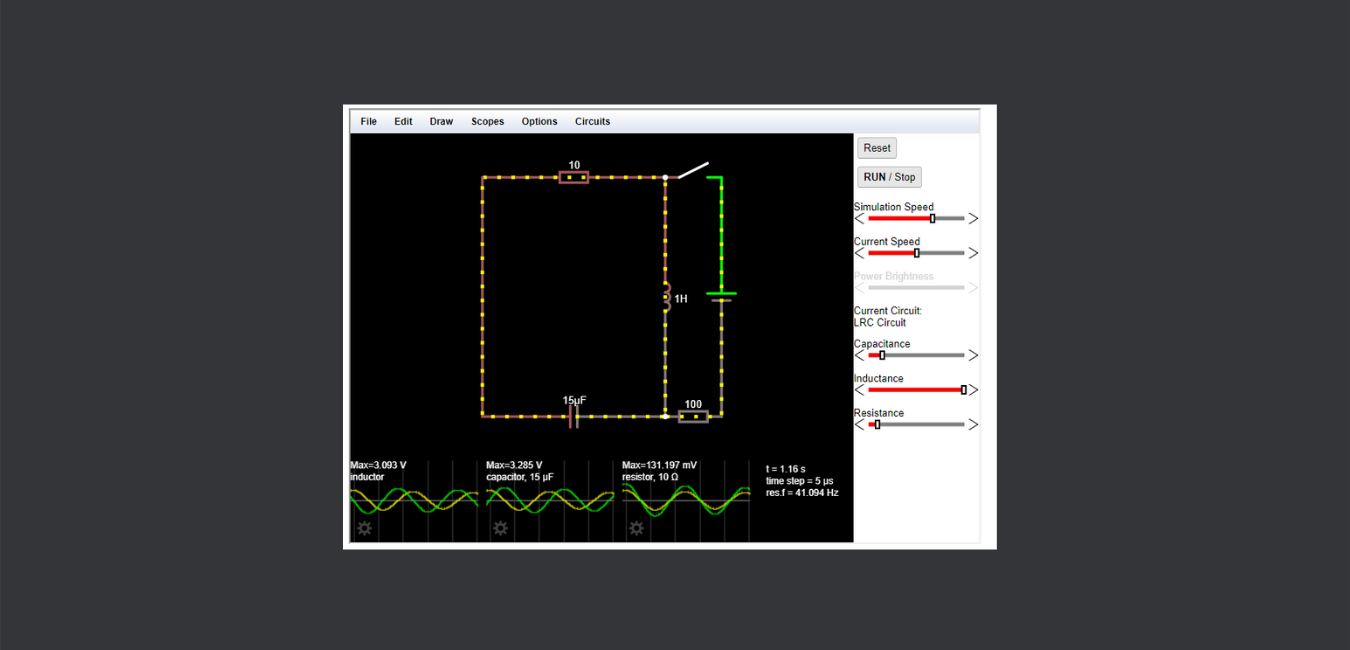
After this first introduction we can start with the assignment.
To start we are going to use a HELLO WORLD board, and we will ad to it a switch button and a LED.
I decided to use a hello.t412.echo board that needs the following components:
- x1 Attiny-412
- x1 FTDI connector
- x1 UPDI connector
- x1 1uF Capacitor
And we will add:
- x1 Red LED
- x1 1kΩ Resistor for RED LED
- x1 switch
- x1 Pulldown 10kΩ Resistor
Then Acording to the Hello world board of Neil, I start making an sketching of the circuit.
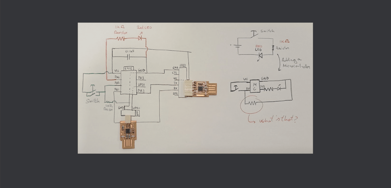
The misterious resistor is a Pull-up resistor that will protect the switch.
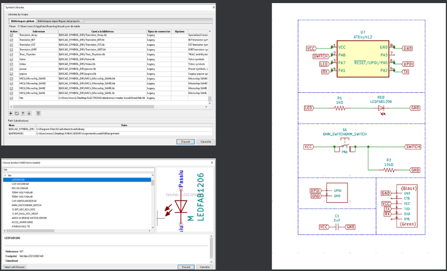
Now, we can open the KiCAD and start to design our scheme.
But, before starting to design, we must import the Fab Academy libraries, there, we'll find all the main electronic compontent that are in the Fablabs.
Once we have the library well seted, we can start to design, importing components from the library, renaming them if it's needed, and connecting the pins.
Also is recommendable to use labels to connect the different pins without creating a labyrinthine mess of lines.

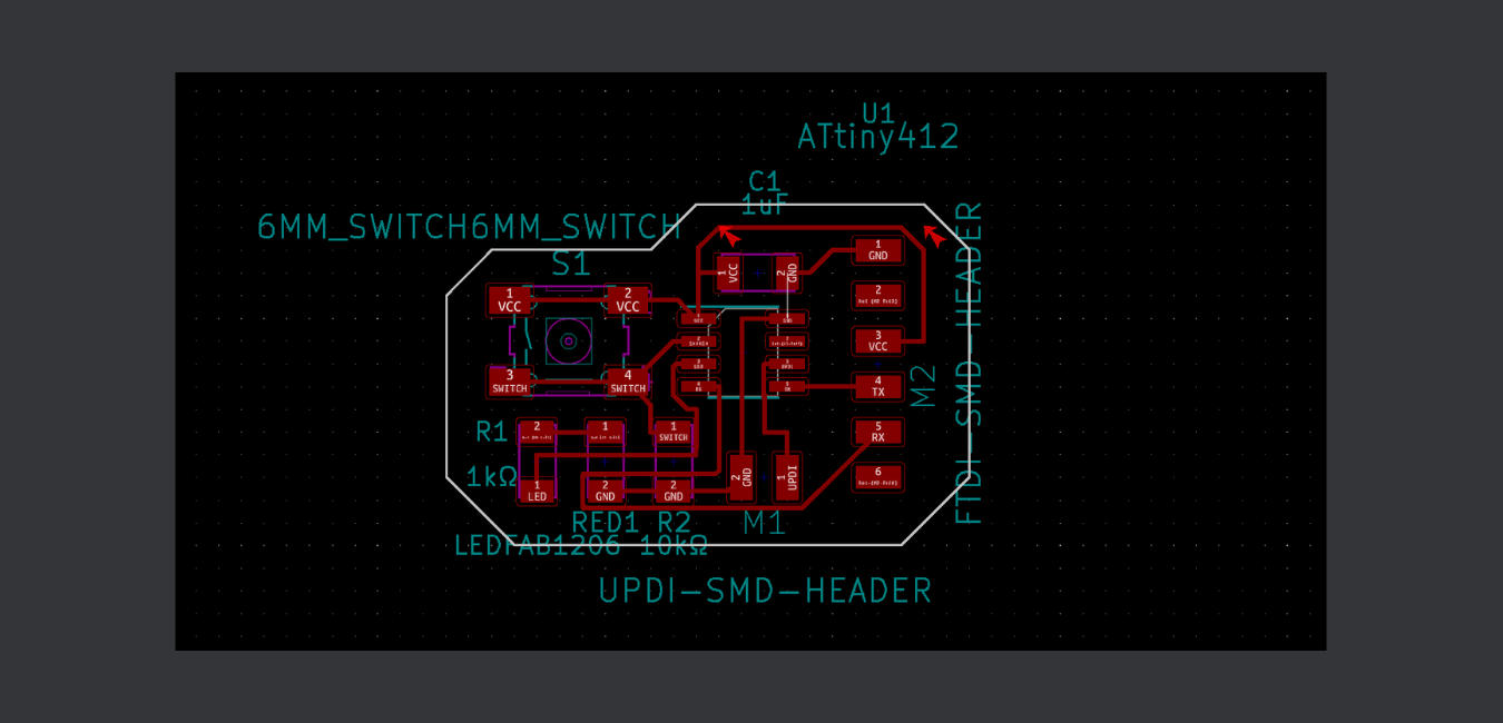
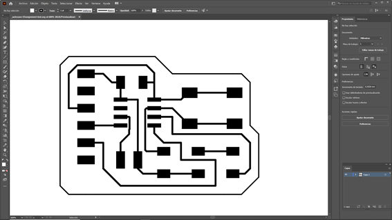
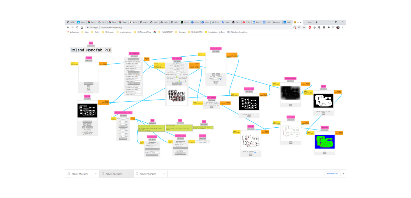
Once we've placed the components and the traces in the right way in kikad we need to export the image but this image will have the outline an the traces
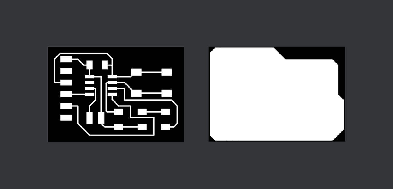
but we need to separate them to be able to creat the traces and outline programes separately in mods.
To do that we'll use Adobe ilustrator to seapre the vectors and create two images one for outline and another one for traces.
After Having the design ready and the PCB cutted, when I was picking the components, I realized that in the lab there was not the kind of microcontroller
that I'd chosen for my design, What a fail! and I neded to re do all the design using a Atiny 1614.
The problem is that I can not go to the Fab Lab BCN very often because I'm working in Valldaura Labs and with that mistake I lost my chance in Barcelona Facilities
cutting a wrong board.
But fortunately in Valldaura we have a Roland MDX20 that Eduardo Chamorro and I had been trying to repare and finally we where able to fixe it, adjusting
some code lines of the interface software.
During the First cut, It did the traces very well, but when it was cutting the profile of the redesigned PCB the problem came back , and then the endmill broke down,
leaving me without chance to try it again because I didn't had any endmill spare in Valldaura.
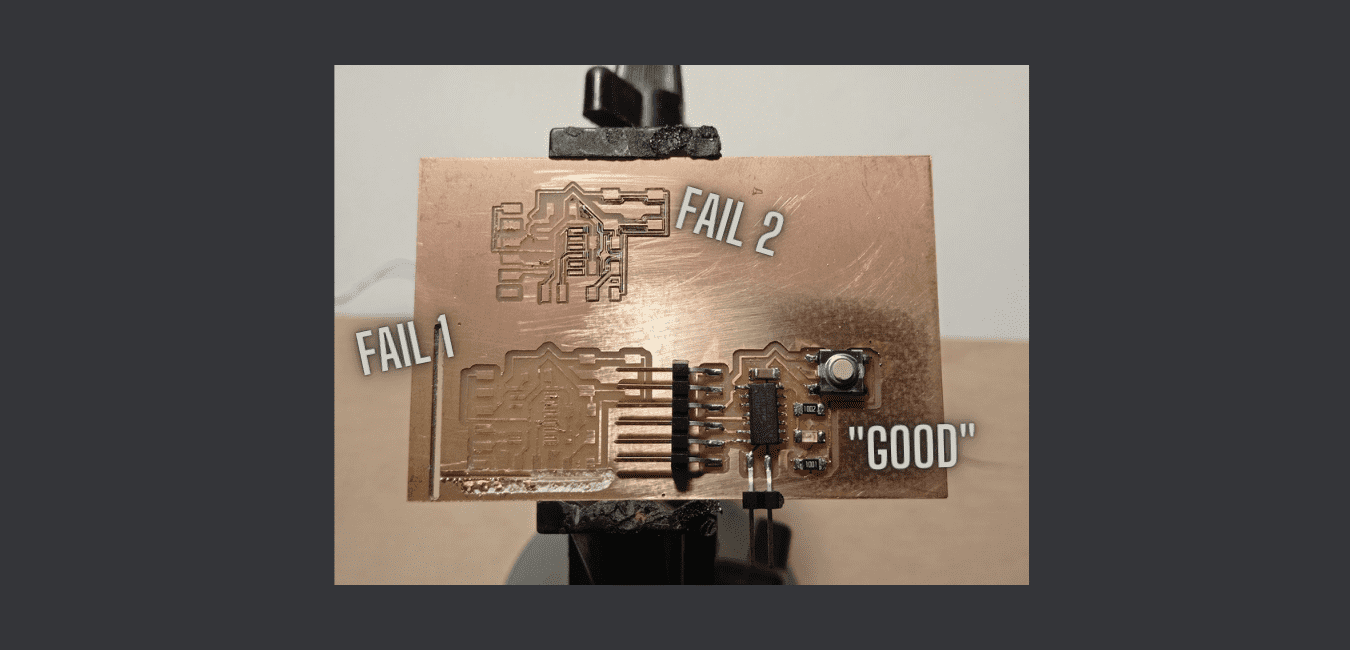
For that reason I had to cut my PCB profile with a dremell, I know... it was a very nasty thing... But the final result is good enough despite the circumstances.
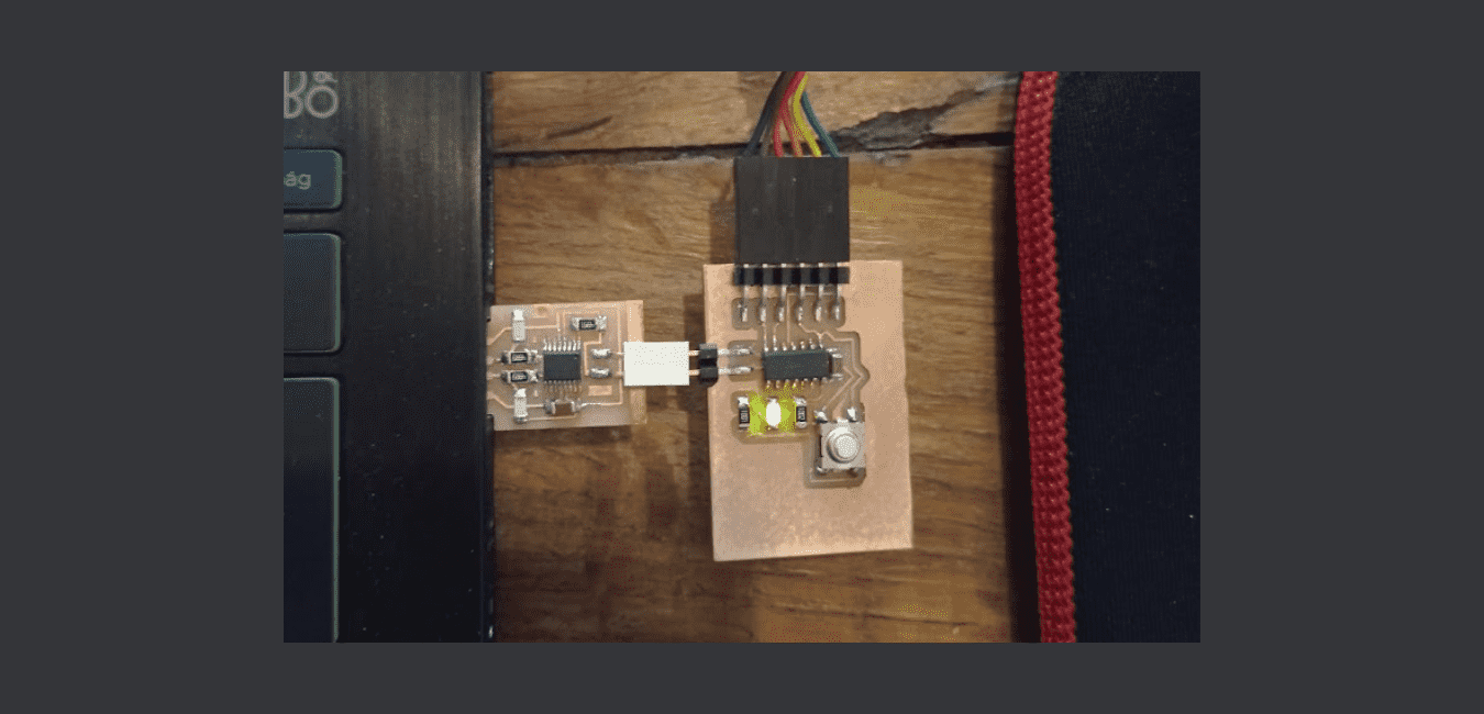
I haven't had enough time to program the PCB before wednesday. but when I conect the FTDI and the UPDI the LED is turned on... I dont know if it is a good indicator...
During the comming week I'll try to finish the assignment testing the PCB.
Files
Find in the link the files of this assignment
FINAL COMENTS
THINGS TO IMPROVE.