Group asignment
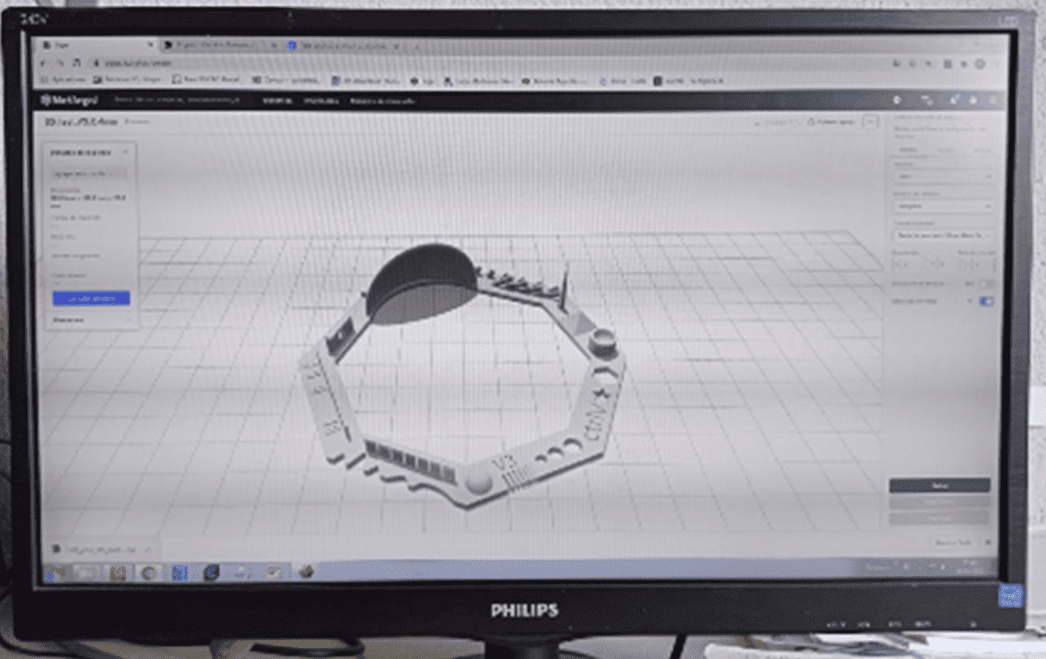
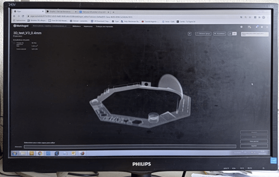
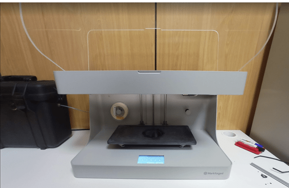
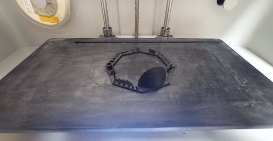
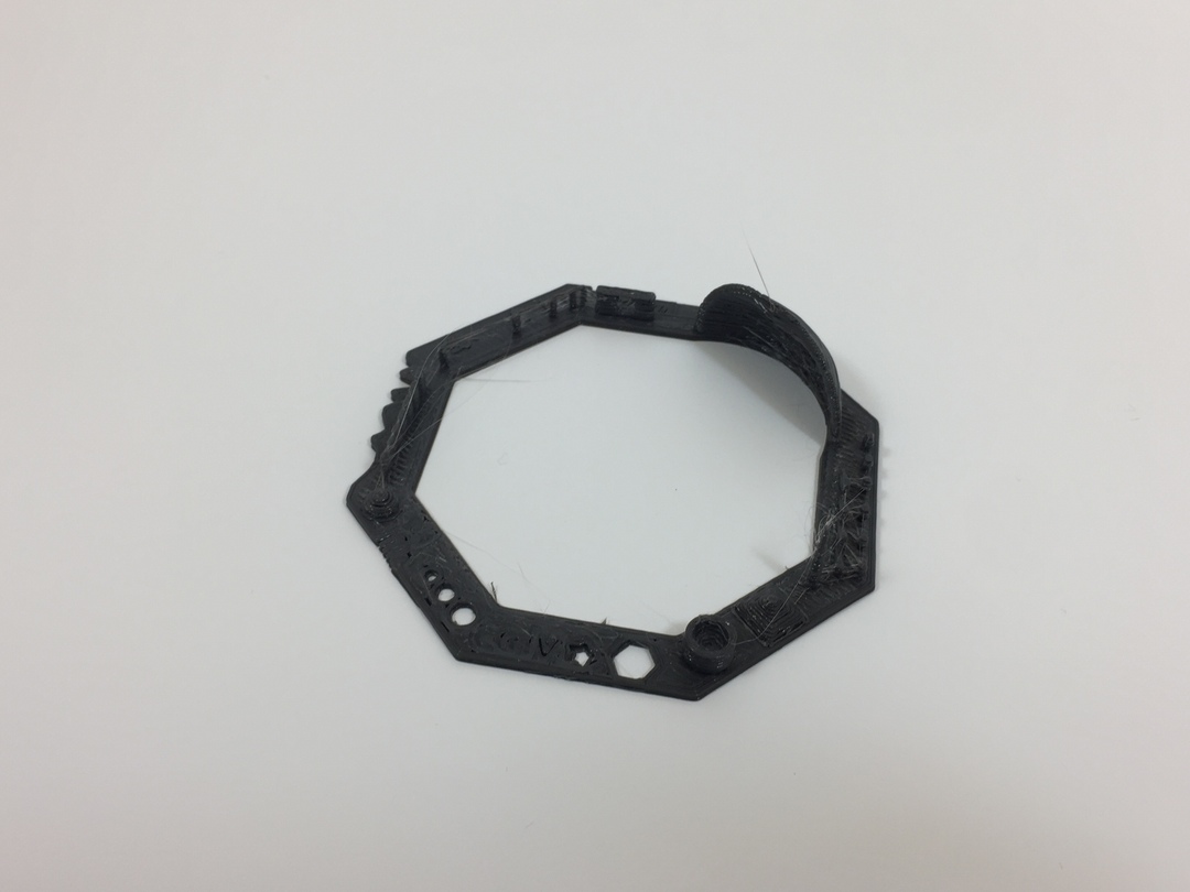
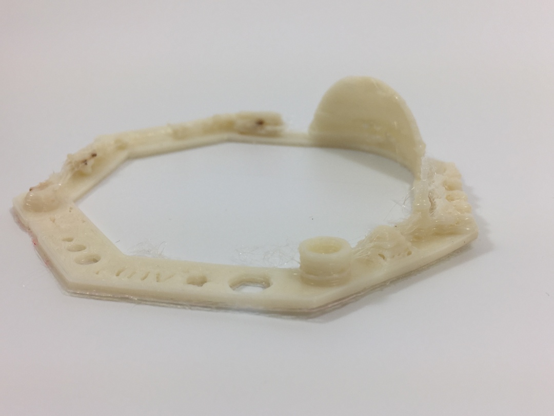
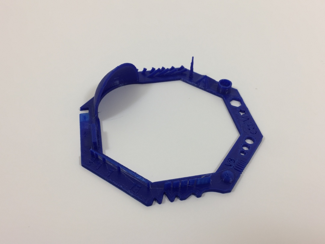
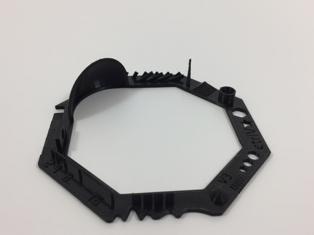
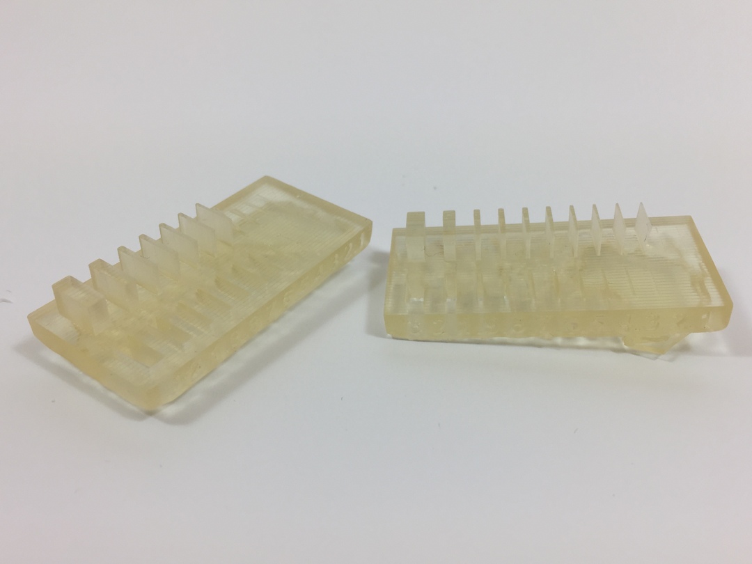
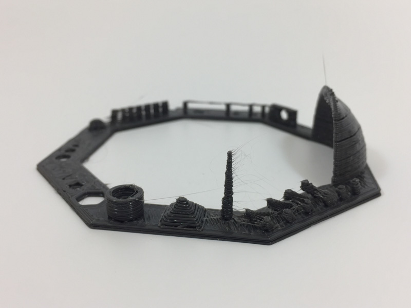
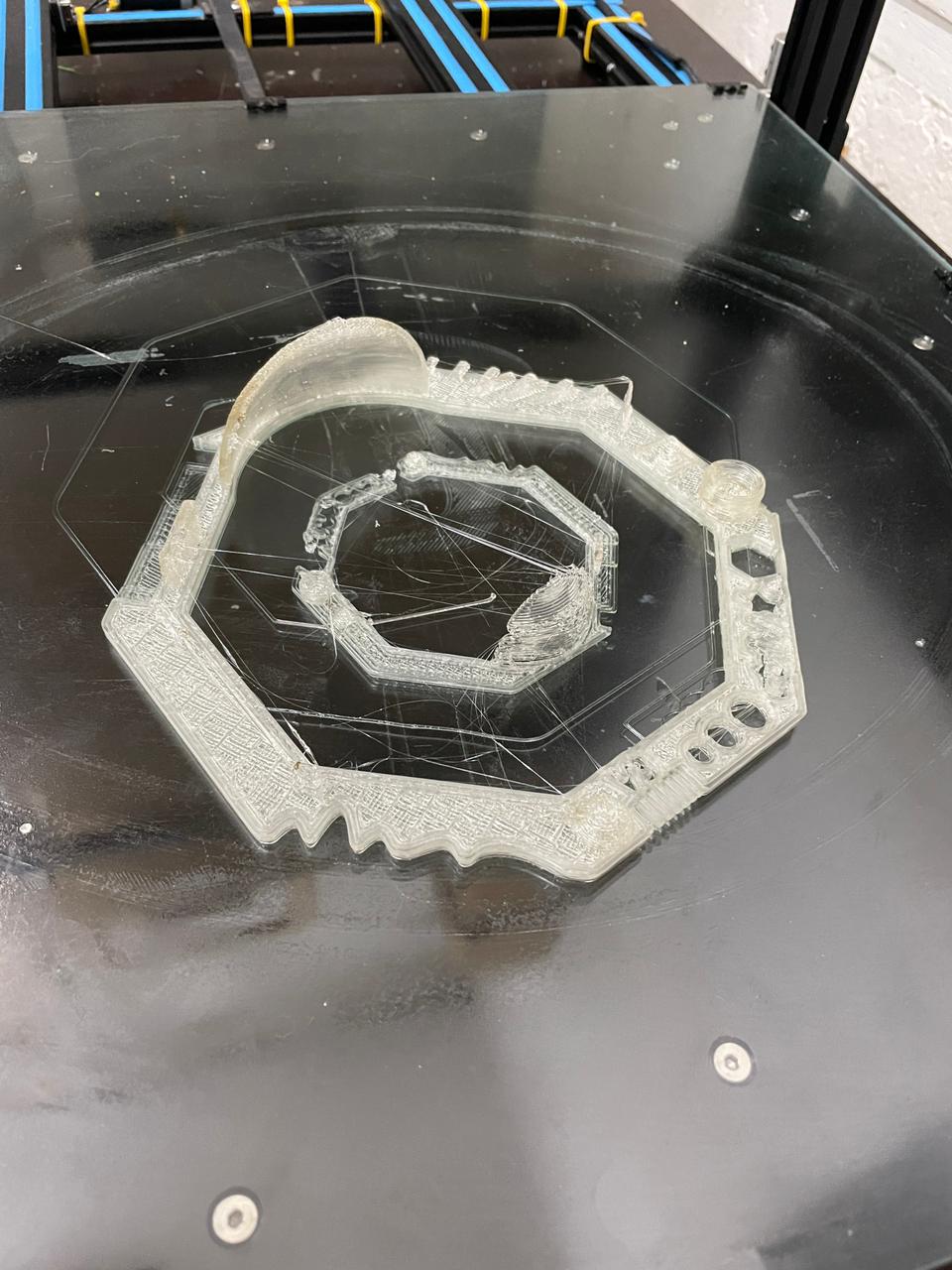
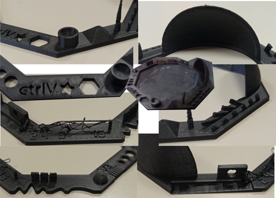
My part in the group assignment was to print the piece that we decided using the Markforged Onix started using a 3D testing model that we downloaded from thingiverse, that shows the printng results of diferent geometries.
Printer Setings
This printer have a lot of presetings, that means that you can only tune a couple of parameters, one of the reasons of that is because this
machine only works with one Material ONYX, but you can add a continuous wire inside the melted onix of Carbon fiber, Glass fiber or keblar.
SETINGS
- Printing Tipe: FDM
- Material: ONYX: Nylon + carbon
- Nozzle Diameter: 0.4mm
- Lyer high: 0.1mm
- Nozzle Temperature: Preseted
- Bed Temperatura: Preseted
- Cooling fan: Yes
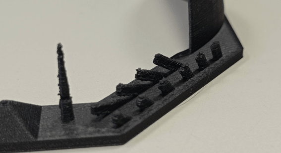
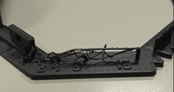
After the test we can reach the folowing conclusions:
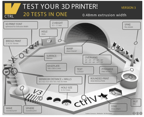
- Nut Size M4 Nut should fit perfectly ✅
- Wave Rounded print ✅
- Star Sharp Edges ✅
- Text Complex Shapes ✅
- Holes Size 3, 4, 5 mm ✅
- Minimal Distance 0.1, 0.2, 0.3, 0.4, 0.5, 0.6, 0.7 mm ✅
- Z height 0.1, 0.2, 0.3, 0.4, 0.5, 0.6, 0.7, 0.8, 0.9, 1.0, 1.1 mm ✅
- Wall Thickness 0.1, 0.2, 0.3, 0.4, 0.5, 0.6, 0.7 mm ✅
- Bridge Print 2, 4, 8, 16 mm ❌
- Sphere Rounded Print 4.8mm height ✅
- Sphere Mix 7 mm height ✅
- Pyramide 7 mm height ✅
- Overhang 25, 30, 35, 40, 45, 50, 55, 60, 65, 70° ✅
- Warp does it bend? ✅
- 3D Print Font optimized for 3D printing ✅
- Surface Flatness ✅
- Size 100 x 100mm x 23.83 (10mm width) ✅
- Spike minimum Layer Time, 21 mm height from Bottom (include Baseplate) ✅
- Hole in Wall 4 mm diameter, check for proper print ✅
Results with the other printers in the LAB
REP RAP BCN3D PLUS
- FDM
- Material: PLA
- Nozzle Diam.: 0.6mm
- Cooling Fan: No
- Bed Temperature: 40ºC
- Nozzle Temperature: 250ºC
- Result: Not very precise
- FDM
- Material: TPU
- Nozzle Diam.: 0.4mm
- Cooling Fan: No
- Bed Temperature: 40ºC
- Nozzle Temperature: 240ºC
- Result: Very Bad results
AnyCubic
- FDM
- Material: PLA
- Nozzle Diam.: 0.4mm
- Cooling Fan: YES
- Bed Temperature: 60ºC
- Nozzle Temperature: 210ºC
- Result: Good result
Ender Pro 3
- FDM
- Material: PLA
- Nozzle Diam.: 0.4mm
- Cooling Fan: YES
- Bed Temperature: 60ºC
- Nozzle Temperature: 200ºC
- Result: Good result
Any cubic Photon
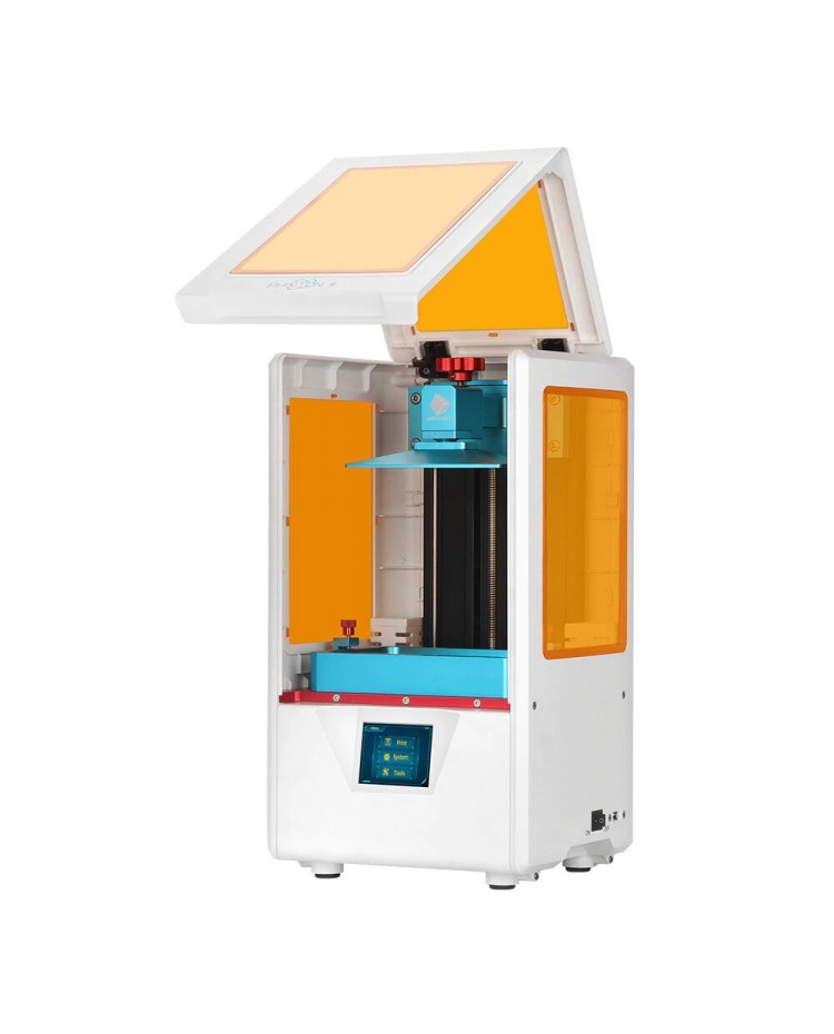
- SLA
- Material: Resin
- Nozzle Diam.: X
- Cooling Fan: X
- Bed Temperature: X
- Nozzle Temperature: X
- Result: Very good result
Prusa MK3
- FDM
- Material: PLA
- Nozzle Diam.: 0.4mm
- Cooling Fan: YES
- Bed Temperature: 60ºC
- Nozzle Temperature: 210ºC
- Result: Good and precise result
Crealty CR10
- FDM
- Material: PLA
- Nozzle Diam.: 1mm
- Cooling Fan: YES
- Bed Temperature: 60ºC
- Nozzle Temperature: 220ºC
- Result: Good and precise result for the scaled model
Markforged Mark two
- FDM
- Material: ONYX
- Nozzle Diam.: 0.4mm
- Cooling Fan: YES
- Bed Temperature: X
- Nozzle Temperature: X
- Result: Good and precise result
Individual asignment
3D Printing
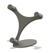
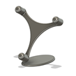
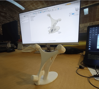
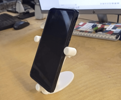
For that asignment I wanted to try the GENERATIVE DESIGN Feature of Fusion 360.
I decided to desing a Phone support
What is the generative
Now I'm going to explain all the process that I've followed.
1- Design and 3D model the main pieces. I've only modeled the suports, becuse I want that the generative desing feature of Fusion 360 generate the part that
join both pieces in a optimiced way.

2- Define the Forces that the object will need to resist.
I added a compresion force and two torkes in x and Y axis.
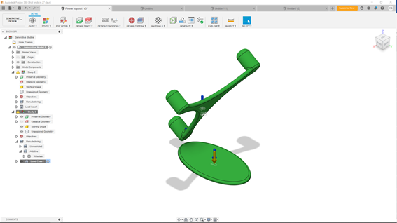
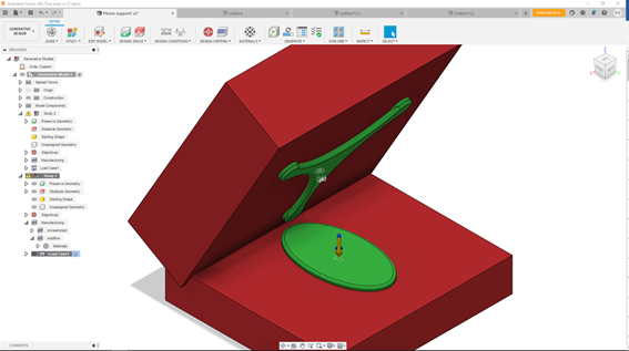
3- Define the volumes where the program must not generate any geometry, you can see the red boxes in the image
4- Define the criteria that we want to follow to generate design.
First, we have to define if we want to minimize the mass o increase the stifness of the piece. In my case, reduce the mass.
Secondly, Define the manufacturing process, additive, casting, milling. In my case additive
5- Then, when everything is setted, we can run the generation.
The program'll make 2 different studies, creating 2 different geometries.
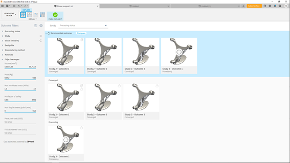
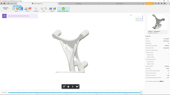
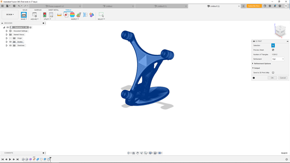
6- After that we can preview the piece, and exported as a solid model, to edit it if we want.
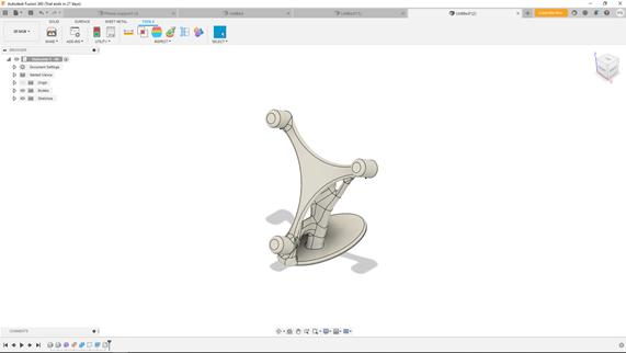
6- Finally We can export the solid model as a STL. to open it with CURA and prepare the 3D printing program.
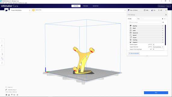
8- For Our Piece, we used the following parameters.
- Machine: Prusa MK3
- Filament: PLA
- Nozzle Temperature: 210ºC
- Bed Temperature: 75ºC
- Bed Sticker: Dimafix
- Layer height: 0.15mm
- Wall thigness: 0.8mm (2 rounds)
- Top and Botom thigness: 0.8 (5 layers)
- Infill: giroid 20%
- Support material: YES

3D SCANNING
STRUCTURED LIGHT
The principle of structured light scanning. The object is illuminated with a plane of light or a light patern that intersects the surface of the object
as a deformed stripes, which is observed by an offset camera.
The projector and camera are accurately calibrated so that 3D locations can be recovered by triangulation.
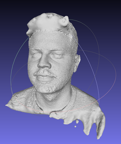
Before FabAcademy I had the oportunity to work an test different structured light 3D scanners.
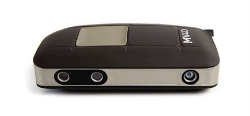
I started working with Pocket Scann of Mantis Vision.
This one, is a good scanner but the main problem that it have is that after scanning the object, needs a lot of post processing, you need to merge manually the point clouds,
and when you have the mesh, you have to work a lot with a mesh design software like MeshLab to close the surface an achieve an smoth result.
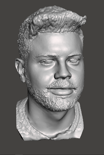
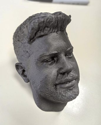
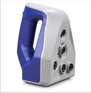
On the other hand I was able to try two different scanners of Artech in a expositions faire in Barcelona called In3dustry.
They are very expensive scanners but as you can see in the following pictures their acuracy is amazing, achiveing
that results without any complex postprocessing, the model is already done by the softawre at the time you finish the scaning, then you can export directly the STL.
You only have to press the button and sweep all the surface that you want to scan.
Artech EVA
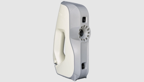
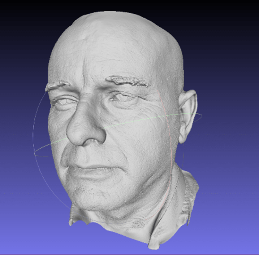
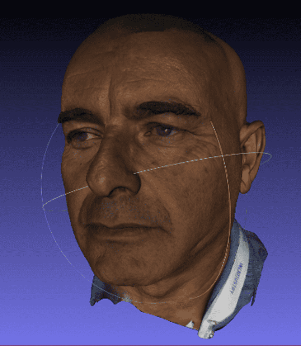
Artech SPIDER
PHOTOGRAMMETRY
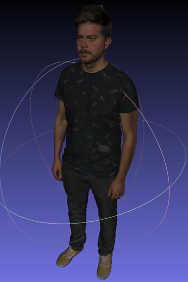
On the other hand for Fab Academy I wanted to try a new kind of 3D Scanning, and I decided to work with Photogrammetry scanning.
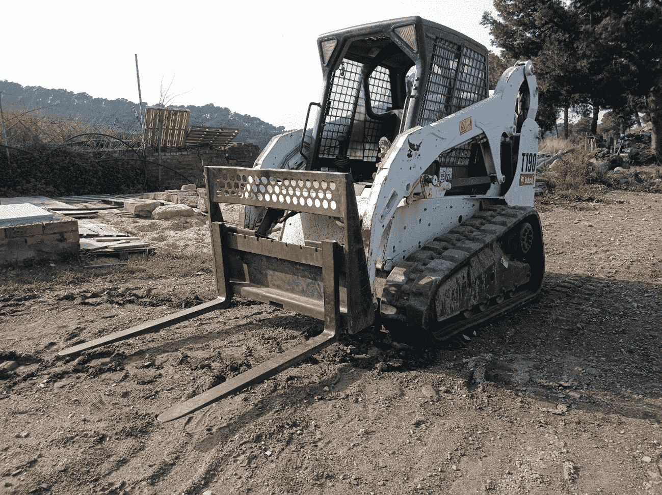
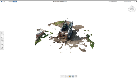
Taking some Pictures with my smartphone, and working with Autodesk ReCap Photo I tried to manage to Scan a BOBCAT machine that we have in Valldaura Labs.
First, I took several pictures around the bobcat, trying to follow an orbital strategy
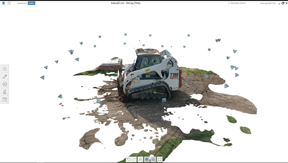
Once I had the pictures imported to my computer, I imported them in RECAP and started the process to create the 3D Model.
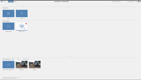
After a long time that the software neded to create the model, the file was ready to export.
In that picture, you can see the aproximate point from where I took the photos.
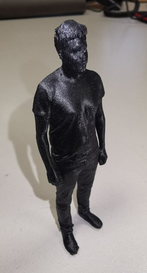
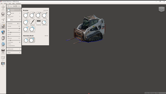
After exporting the model in OBJ. and STL. I decided to open it in the MeshMixer, a software from Autodesk, that let yu edit meshe like clay, correct errors,
close pockets, etc. But I decided to use it to remove the floor of the model and give it a better finishing.
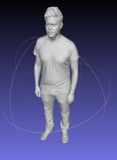
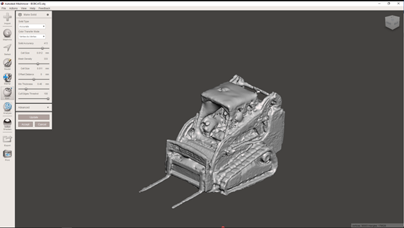
In that Image, you can see the result without the texture. In that way Te errors and unprecisions ar easier to percive.
3D Scaning Conclusions
Comparing the different types of scanning, we will take into account the following aspects:
- Quality of the finish
- Need for post-processing
- Price
Therefore we can say that structured light dryers give us a very detailed finish and that the need for post-processing is closely linked to
the price of the scanner and the associated software itself.
On the other hand, scanning by photometry is much more affordable and sufficient for large volume pieces, buildings and surfaces, or parts
that do not need great detail
Files
Find in the link the files of this assignment
FINAL COMENTS
THINGS TO IMPROVE.