Milling Machine
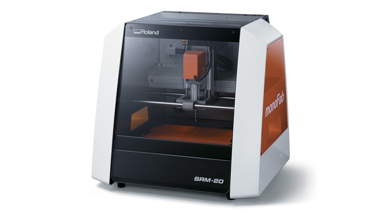
The Machine: Roland SRM-20.
This is the control panel
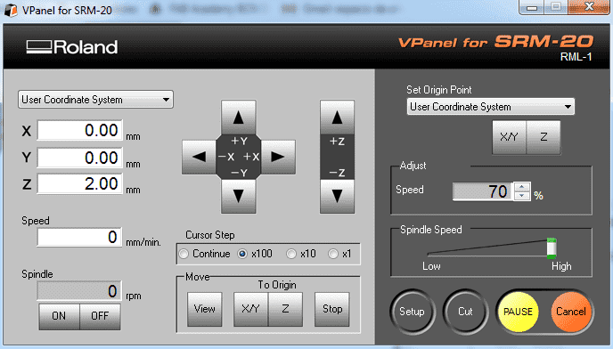
That can be used to:
- Move the axis (XYZ)
- Switch On/OFF the spindel motor
- Set the origin
- Launch a program
Setting up the Machine step by step
1- Plane the sacrificial board (if is not done yet) because we'll need a perfct plane working surface.
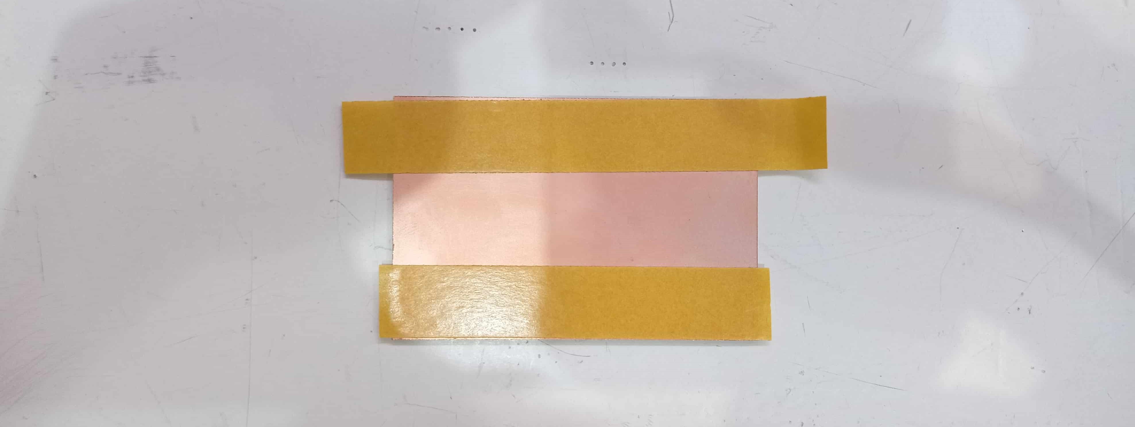
2- Stick the copper board to the sacrificial board using double side tape.
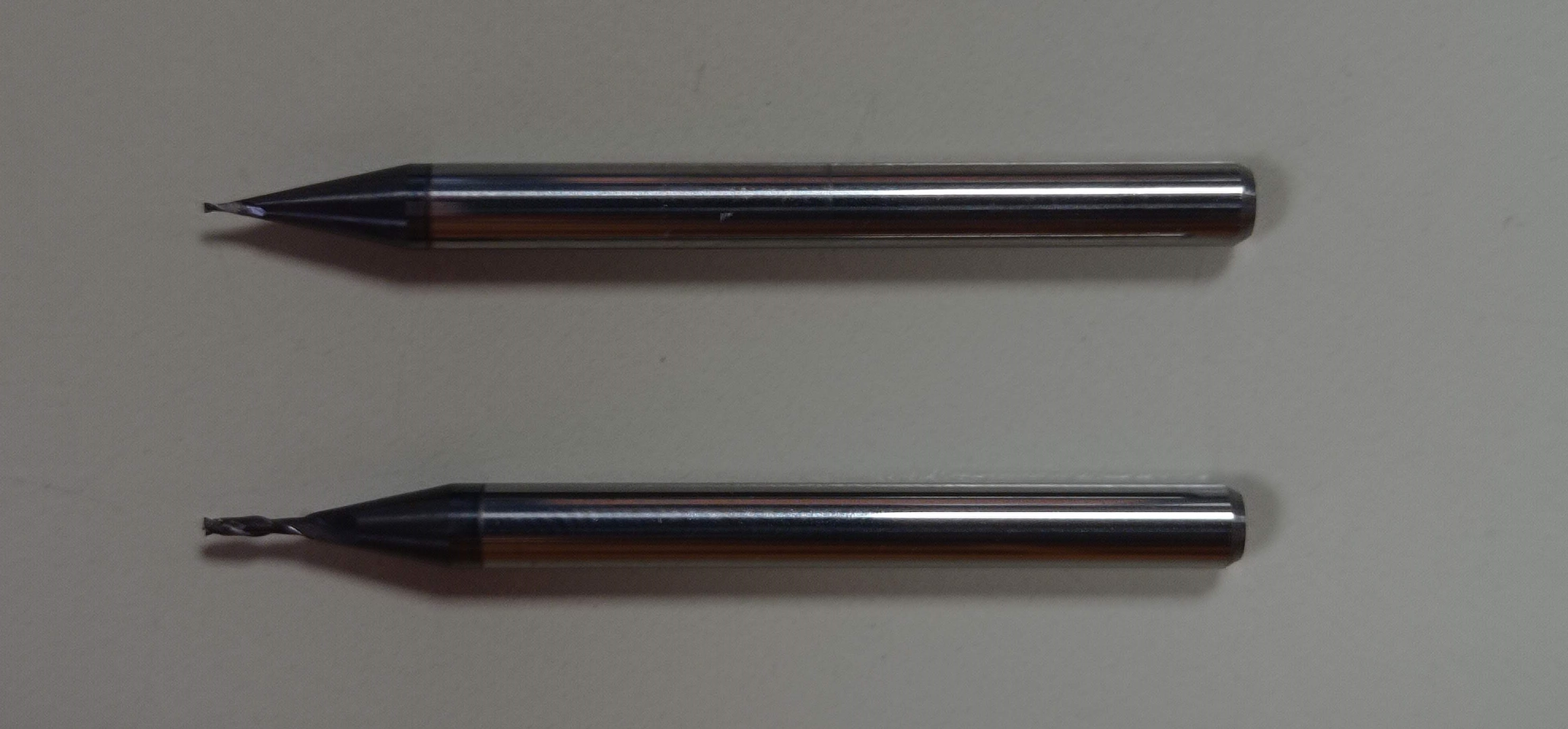
3- Select and plug in the endmill:
- 1/64 for traces
- 1/32 for outcuts
4- Set the origin
-Mooving the endmill, using the software interface, to the point on the board that we want to set the 0,0,0.
Now, the machine is ready to start cutting, but before we need to prepare the gcode.
Create a Milling Gcode step by step
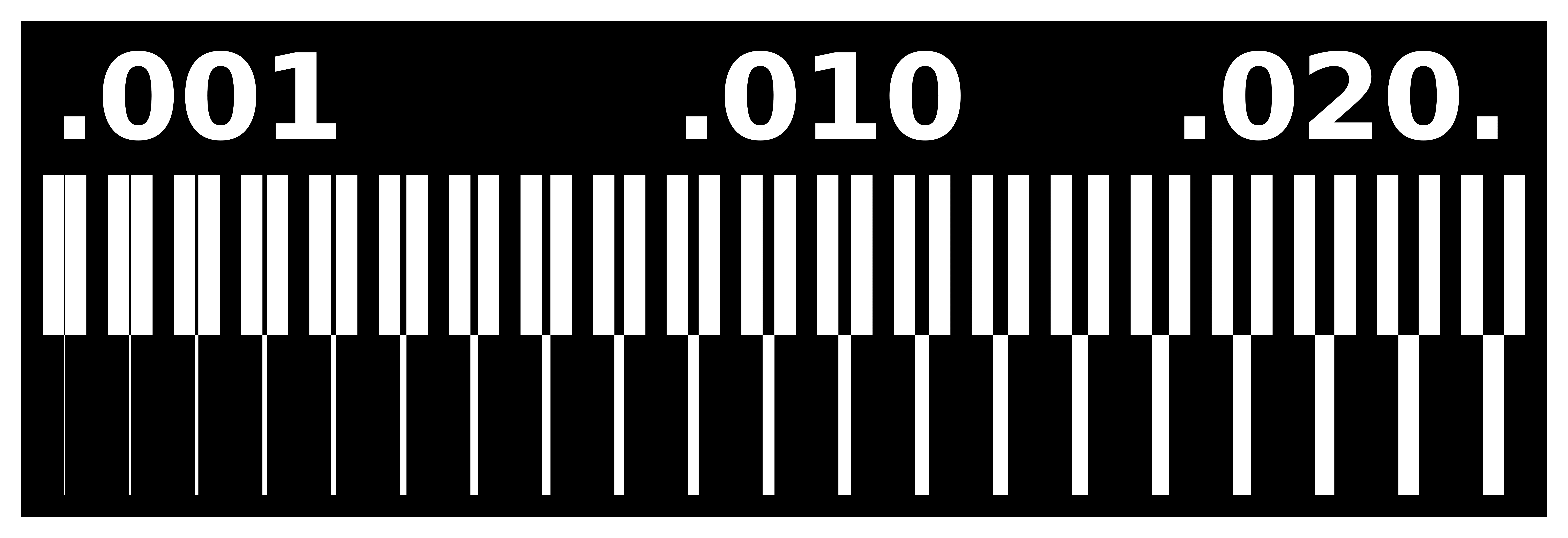
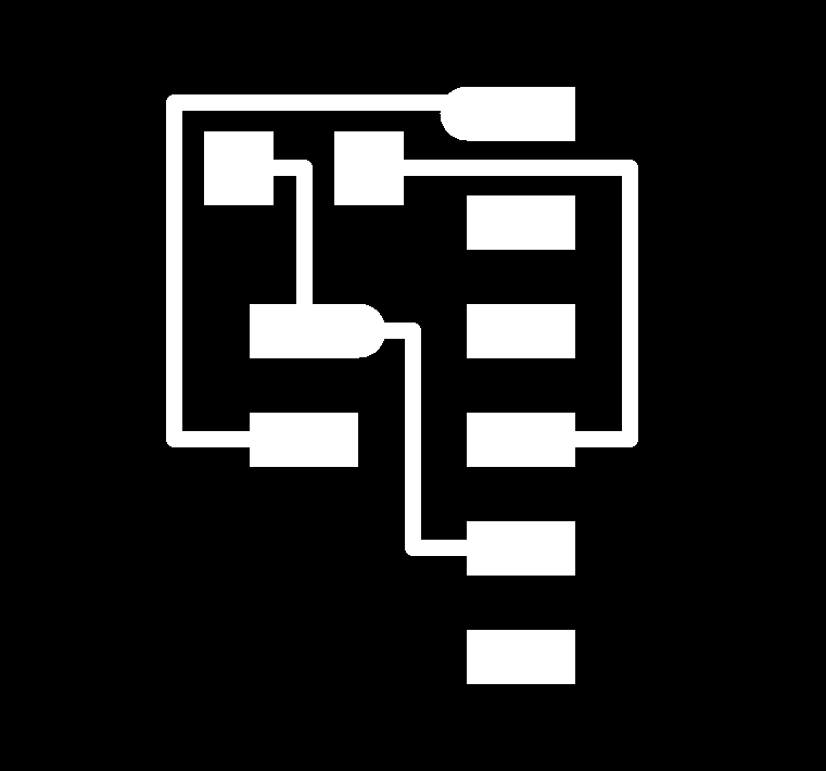
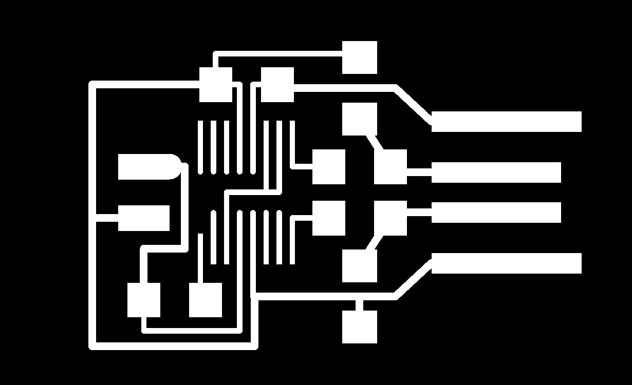
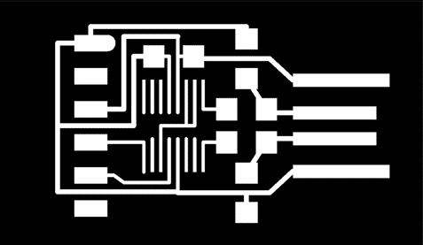
1- Desing or Download the design that we want to cut.
- The format it have to be PNG in a good resolution.
- We must create 2 images, one for the traces (left), and an other one for the outcut (right).

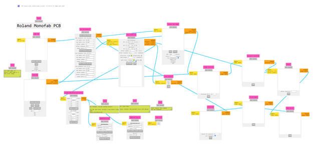
2- Open modsproject.org > programs > open program > Roland - SRM-20mill PCB
3- connect the "Roland SRM-20 milling machine" file with "save file" to be able to download the Gcode after calculatig.
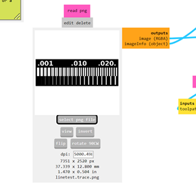
4- Upload the traces image in the PNG window
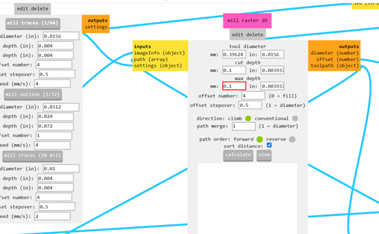
5- In "Set PCB defaults"
- Select the endmill 1/64 for traces
6- In "mill rester 2D"
- Define the cut depht = 0.1
- Define the max depht = 0.1
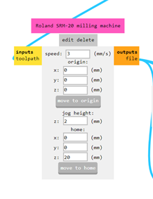
7- In "Roland SRM-20 milling machine"
- Define the speed= 3 mm/s for traces
- Define the origin at (0,0,0)
- Define the home at (0,0,20)
8- In "Mill raster 2D"
-Press Calculate
9- When the calculating process finish, pick the Gcode file from downloads
10- When we finish this process we have to repeat it for the out cuts but changing the following parameters:
- Select the endmill 1/32
- Define cut depht= "default"
- Define max depht= 1.75 (thickness of the copper board)
- Define the speed= 1.5mm/s
11- When we have both Gcodes, and the Machine setted, we have to launch first the trace Gcode.
12- After the traces, clean the board an change the endmill to the 1/32.
13- Set the Z hight. We have to take care to not modify the X,Y origin, only the Z
14- Launch the outcut Gcode.
PCB_Milling from Marc Garcia on Vimeo.
15- Clean the machine and we have our PCB ready!!
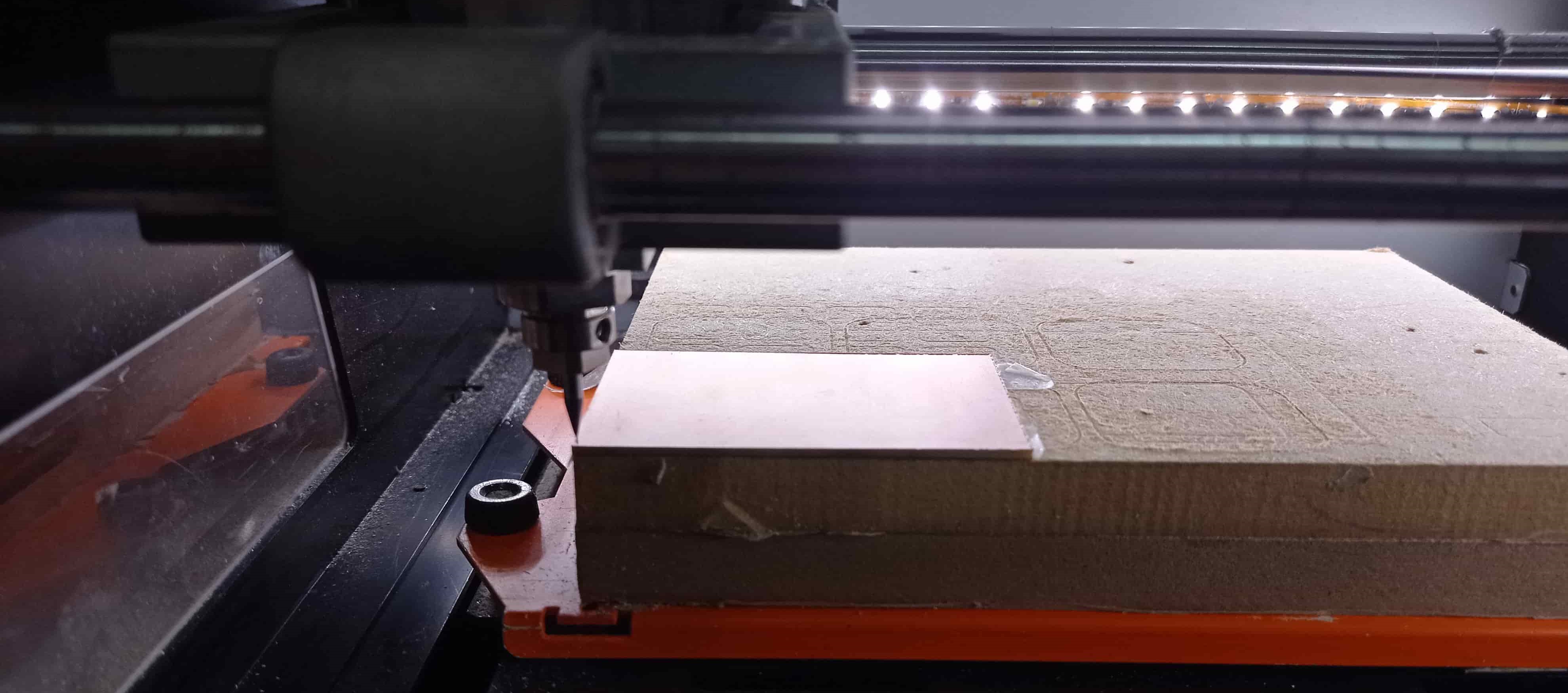
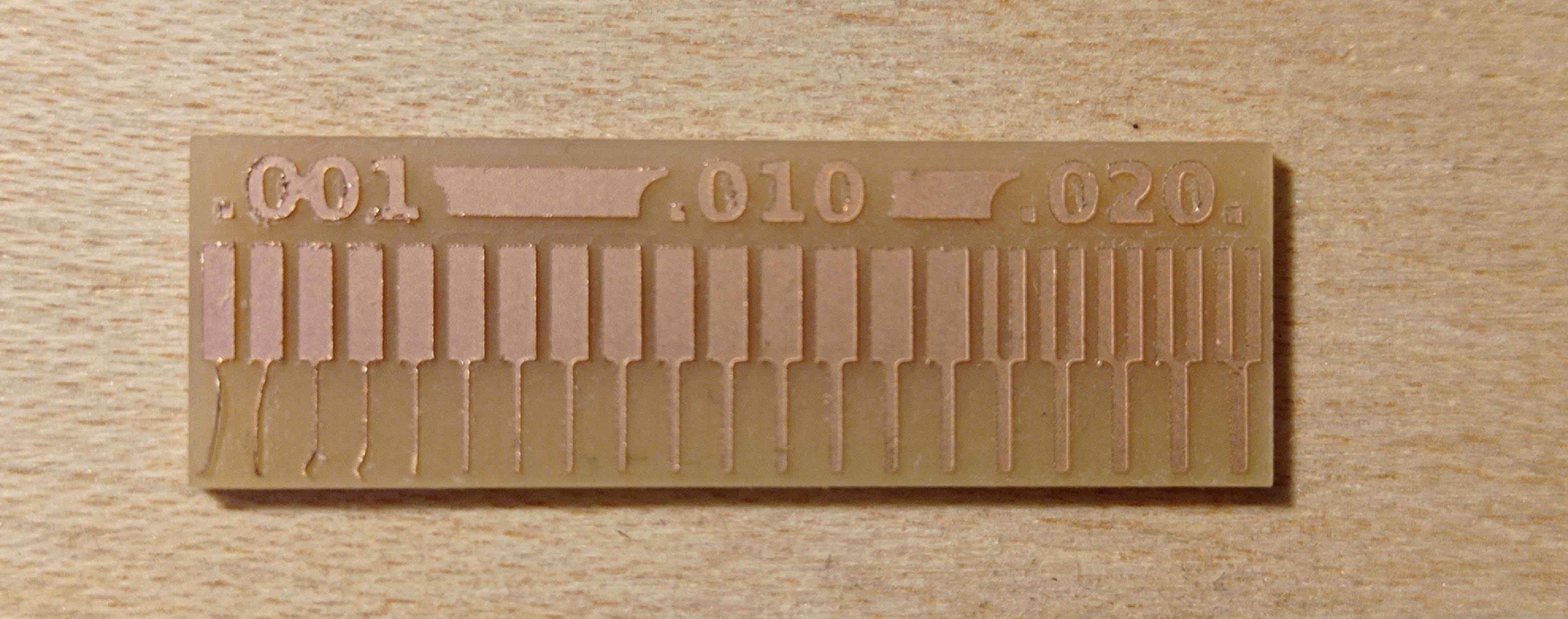
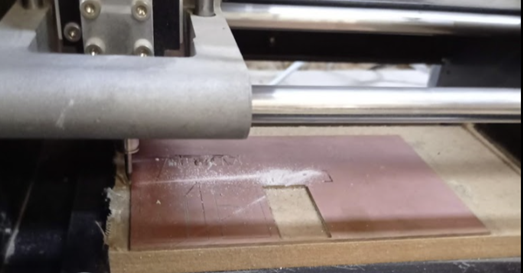
We've been working with a TEST file to see if the machine works properly, and as we can see we've had a good result.
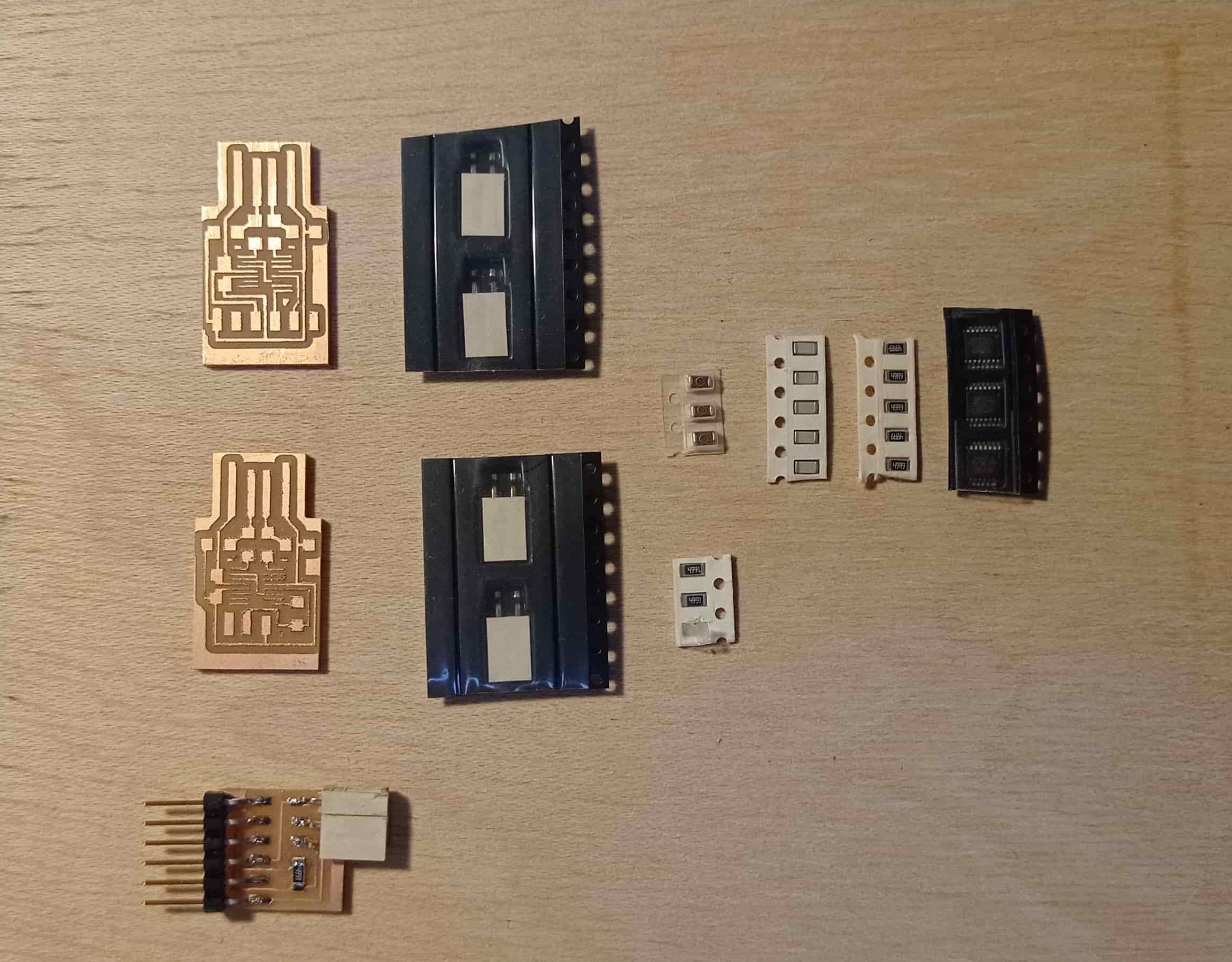
Soldering process
1- Pick the components of the design ( resistors, capacitors, LEDs, connectors...).
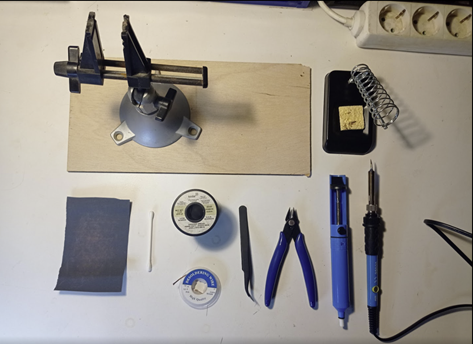
2- Pick the tools
3- Sand the PCB (light sandpaper P1000)
4- Clean the surface with alcohol
5- Preheat the soldering iron at 300º
6- Heat one of the points of the PCB, where we'll attach one of the legs of a component, and add a bit of tin.
7- With the tweezers, we have to pick the component and place one of the legs over the tin point and heat again the tin to solder the component.
8- Then we have to solder the other leg adding more tin.
9- remove excess tin using desoldering wire.
10- Repeat steps 6, 7, 8, and 9 with all the components, and That's it!
Soldering Practice from Marc Garcia on Vimeo
PCB PRODUCTION
Following the steps described before, I proceeded to pick one of the proposed models for the week.
I decided to mill th UPDI and FTDI files because the instructors told us that they'll be very useful for the rest of the Fab Academy.
During the microcontrollers lecture, the instructors taught us the basics, I'm a real noob on Electronics and Microcontrollers,
but more or less I understood how the microcontrollers work and mainly how we can connect and communicate with them.
I decided to cut the following boards, to be able to try different options and test them.
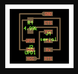
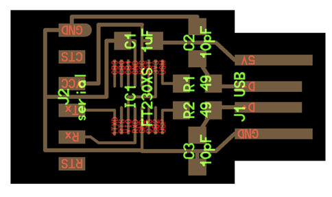
First of all, we need to pick the designs to know the traces, the outcuts and the components that we'll need.
1- Serial UPDI 3

2- USB-UPDI.FT230X

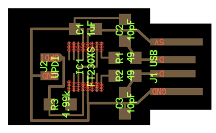
3- USB-serial.FT230xX

After milling using the design PNG, we can take the resulting PCBs and the components. to prepare them for soldering.
Then we can start with the soldering process, previously descrived.
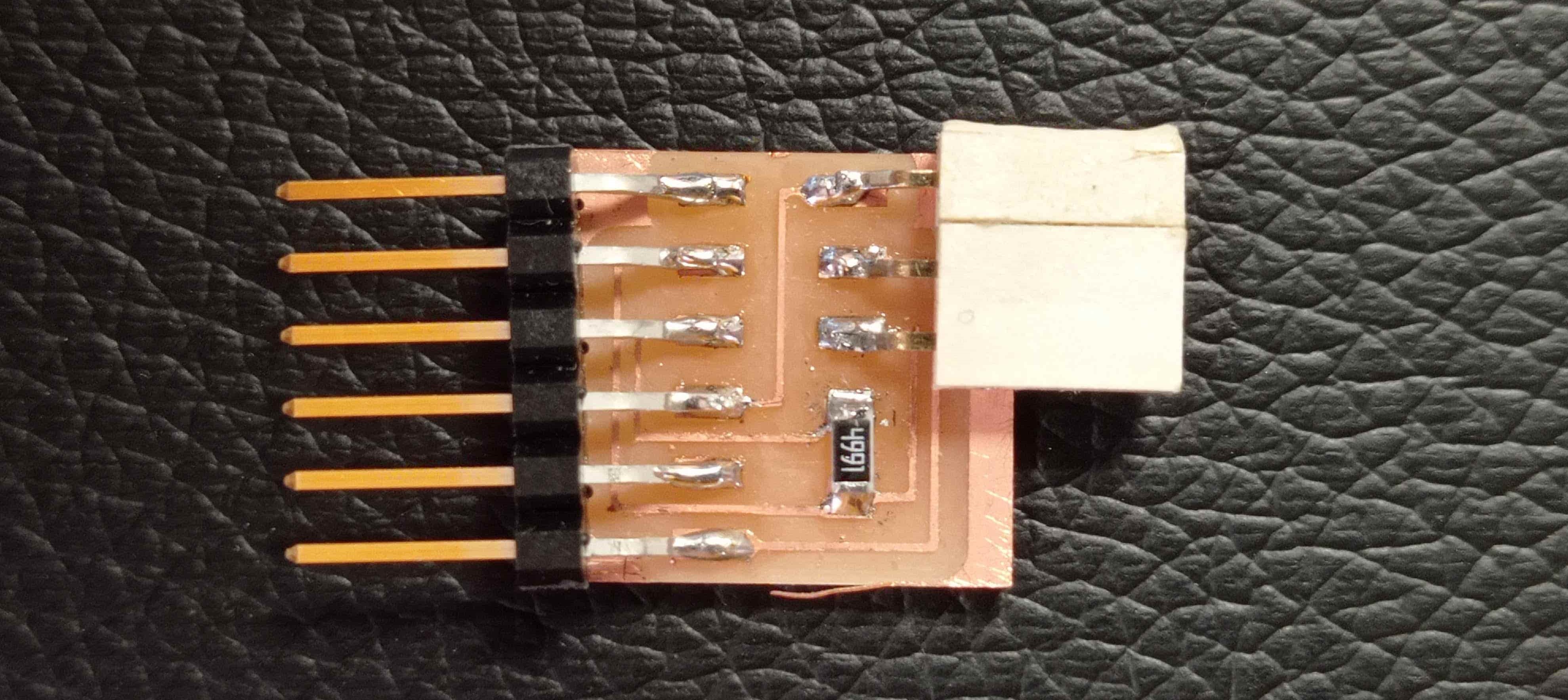
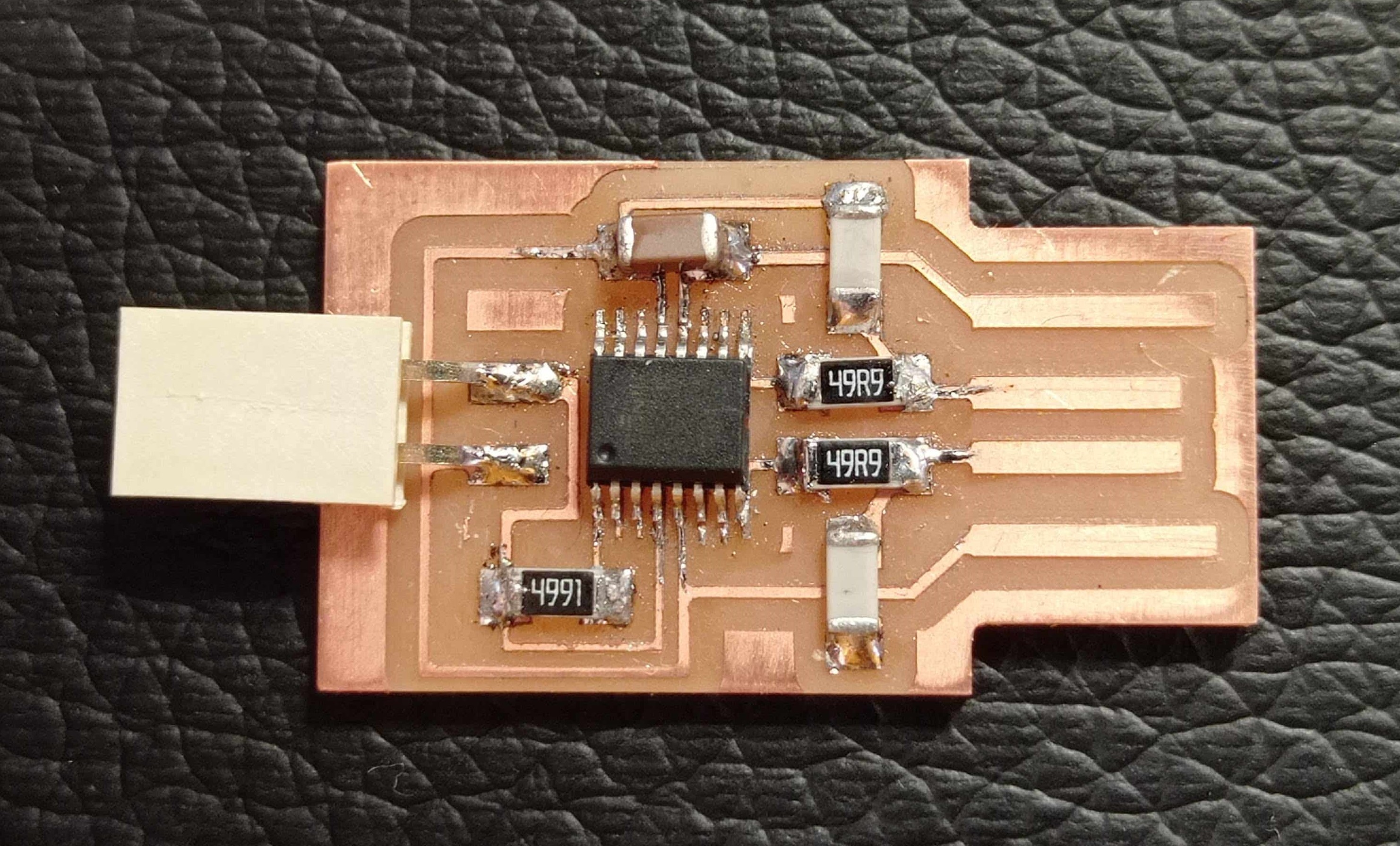

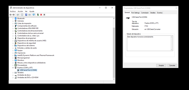
When we have our PCBs ready, we can proceed to test them on our computer.
As you can see in te following image, our PCBs are well reed by our computer.
Setting up Roland MDX-20
In the green fablab in Valldaura, the lab where I'm working, we have a Roland MDX-20.
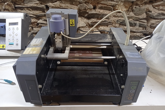
This machine hasn't been used for years and it's not working properly.
For that reason I've been talking with Eduardo Chamorro, one of the instructors in Fablab BCN, to try to find a way to make it work again.
We can create the Gcodes for this machine perfectly with MODS.
But the problem appears when we have to communicate with the machine and launch the program.
For that reason some time ago Eduardo developed an interface to make that process easier and more intuitive.
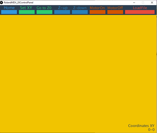
But when we launch the programs, the milling machine is still presenting some problems...
PCB Milling Fail from Marc Garcia on Vimeo.
At the moment we are still working on that to make this machine functional again.