MOLDING PART
3D DESIGNING PART IN FUSION 360
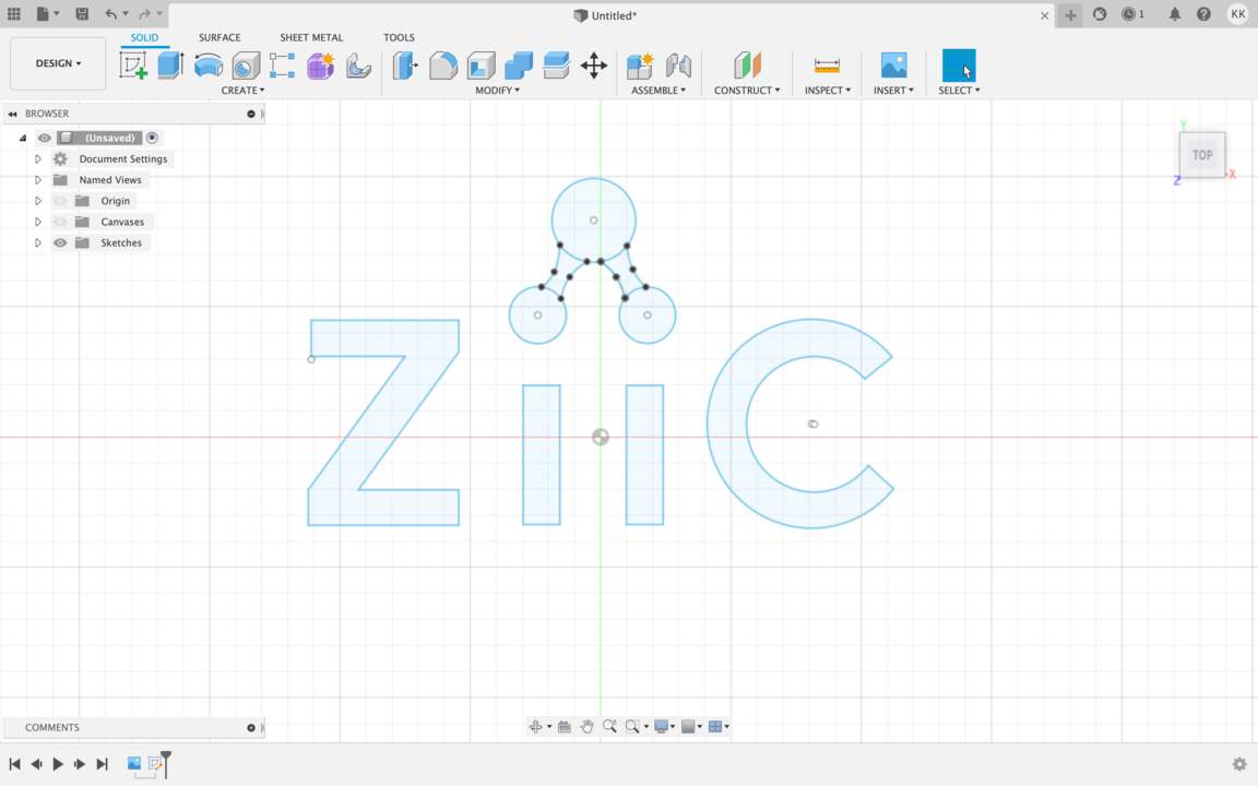
- Place where I am working has its own LOGO and for this week's assignment I will try to make a 3D model of my work logo. As I have a picture of my work logo I just import it in Fusion with commands Insert - Canvas. Then I created a new Sketch and used Line and 2-Point Rectangle for logo letters but for logo icon (molecules) - Circle and 3-Point Arc.
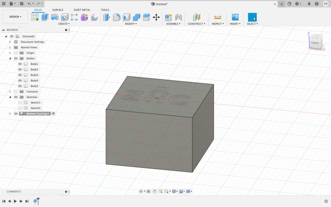
- Then I clicked on the Extrude tool, selected all logo profiles and extruded it 10 mm like a New Body.
- After that I clicked on the Change Parameters and created three new parameters - MarginX, MarginY, MarginZ.
- Then I also defined a stock size like a parameters - StockX = 110 mm, StockY = 88 mm, StockZ = 32 mm.
- Then I created a new Component for drawing Rectangle. Extruded it.
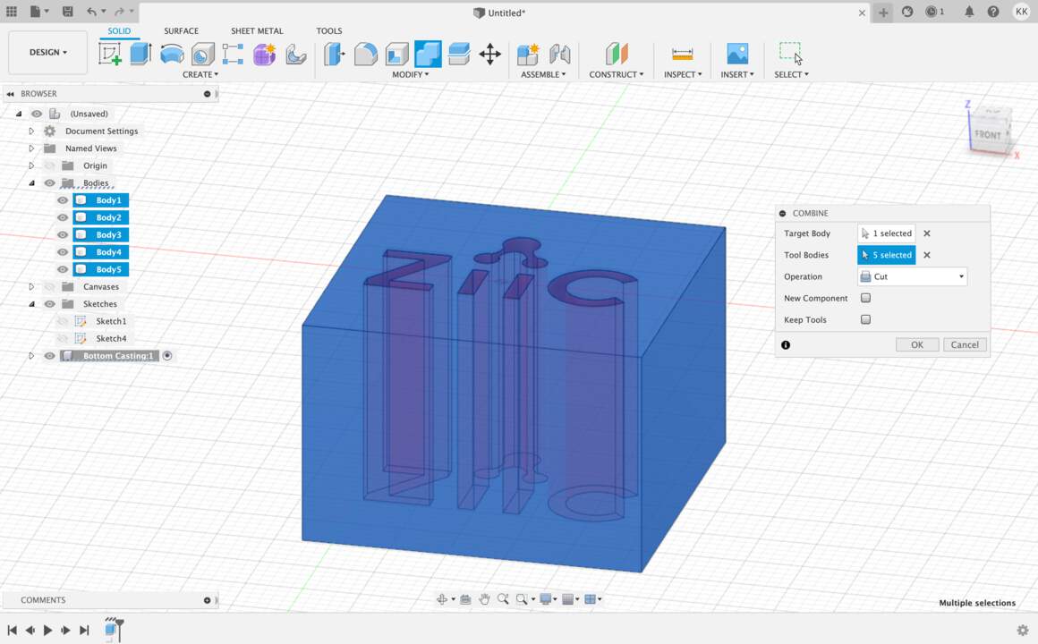
- Then I tried to combine these bodies, for Target Body selected box, for Tool Bodies - logo and operation was - Cut.
- Then I tried to make the second box as a top (the first box was as a bottom). And as I am a beginner in 3D modeling after that I went to work with Vcarve Pro where I will could generate toolpaths and send a file to MDX-40 machine straight.
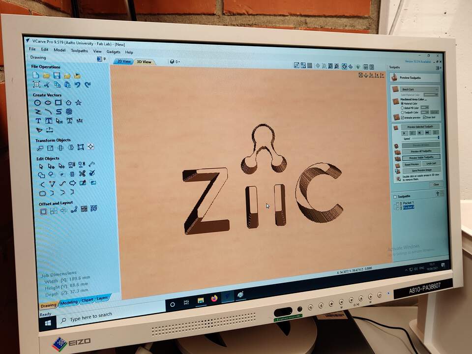
3D DESIGNING PART IN VCARVE PRO
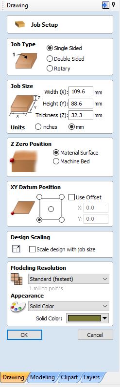
- First of all I defined Job Setup for my model. Job Type - Single sided, Job size - area of the wax mold, Z Zero Position - Material Surface and for XY Datum Position I chose the left corner. Then I imported my sketch from previous software.
TOOLPATHS IN VCARVE PRO
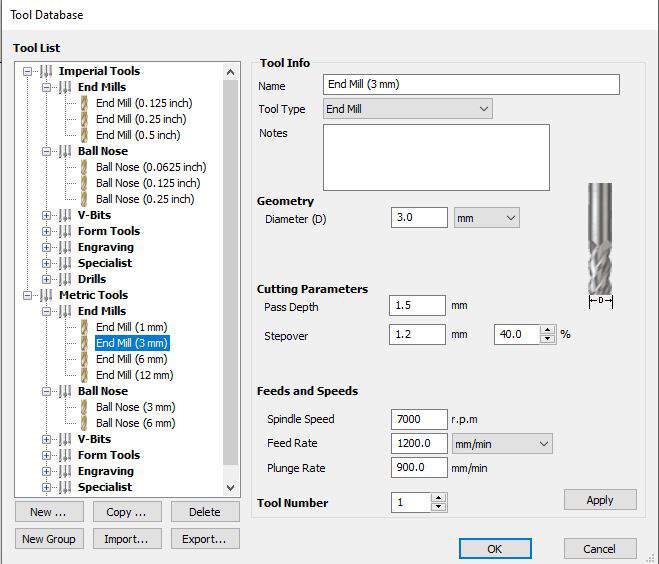
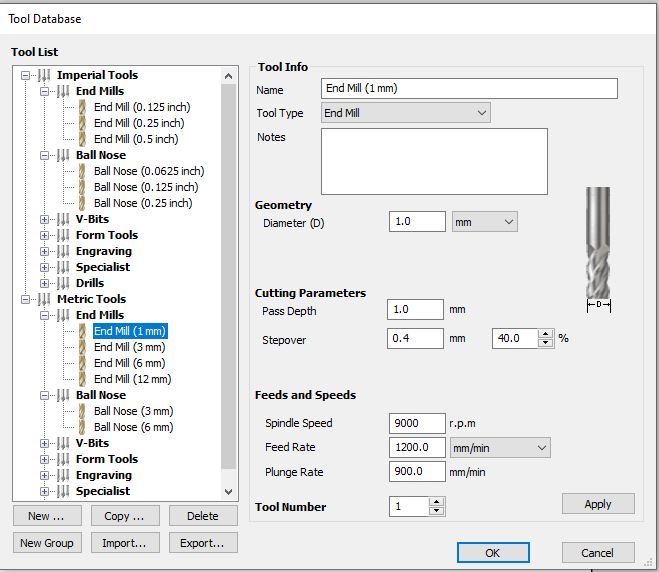
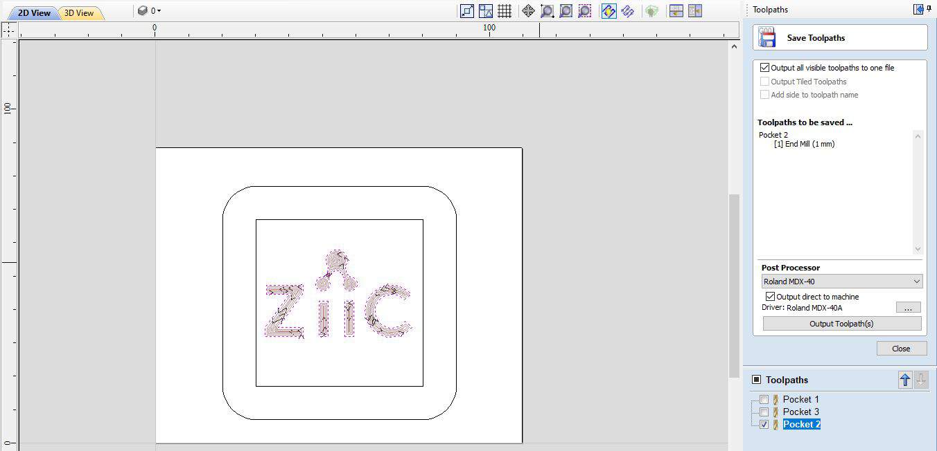
- For external and internal forms I used End mill - 3 mm tool, but for engraving logo - End mill - 1 mm tool and Machine Vectors - Outside/Right and Direction - Climb.
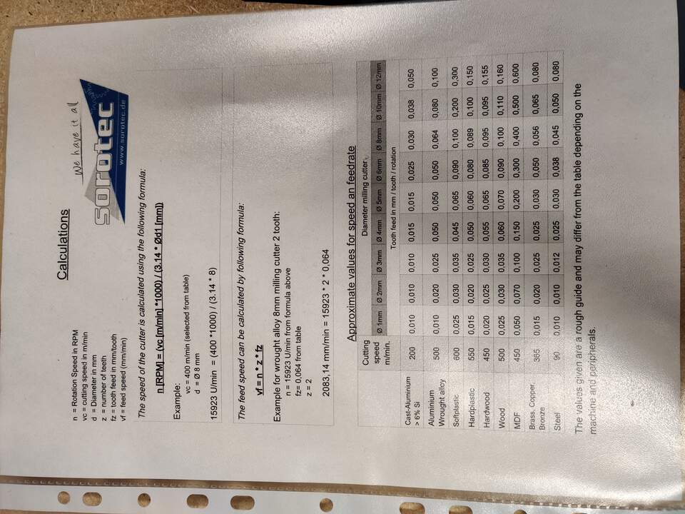
STEP 1 : SPEEDS & FEEDS
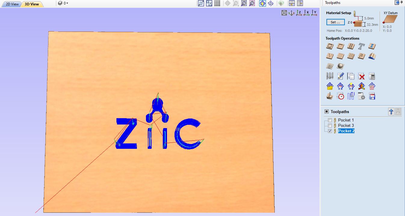
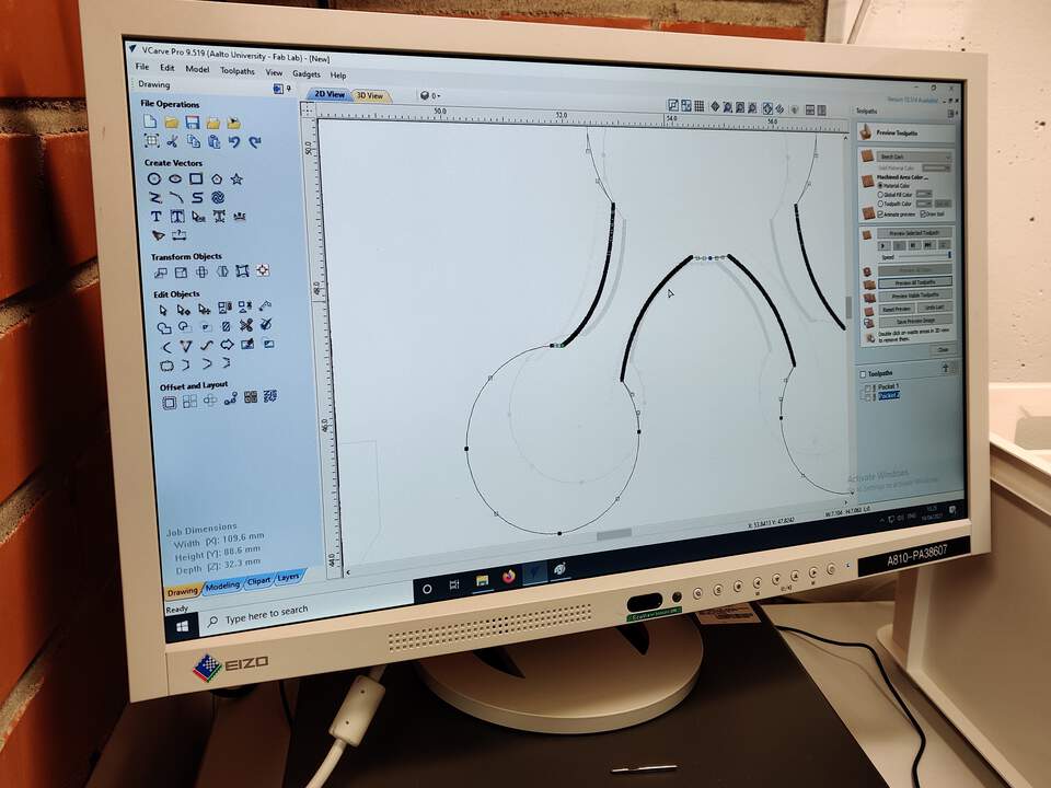
- When I tried to generate toolpaths for the logo which I set up as a 1 mm tool I saw that the icon part hasn't toolpaths because the path looks too small for the tool. For that in VCarve I manually made a change in design - increase the icon.
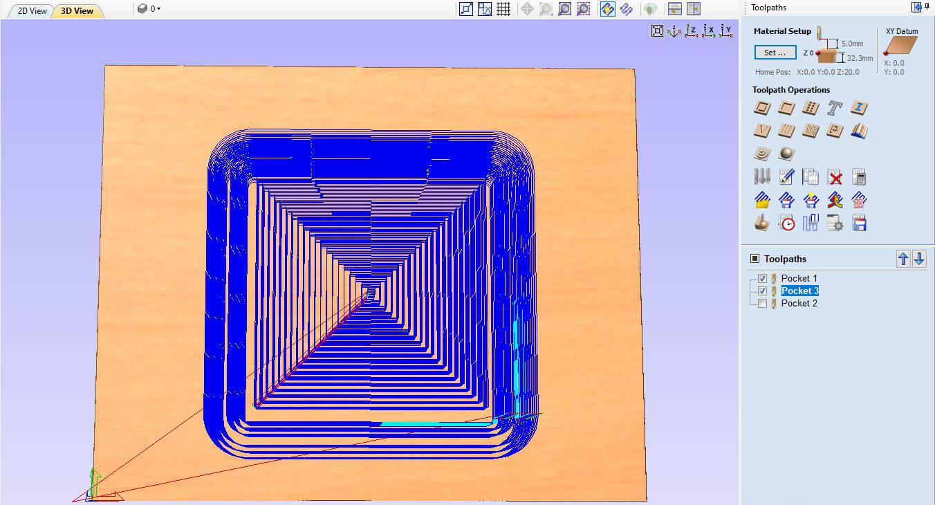
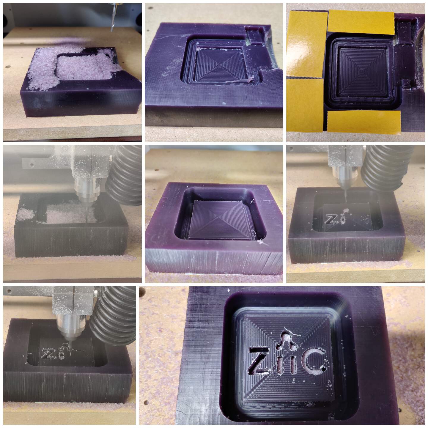
- I started with cutting external and internal forms and in VCarve it is so easy to select and send parts that you want to cut to MDX-40 with the Output Toolpath(s) button. Be careful before setting up X,Y,Z origin positions in VPanel software. In the final step I engraving a logo in the same way - just selected and sent a file.
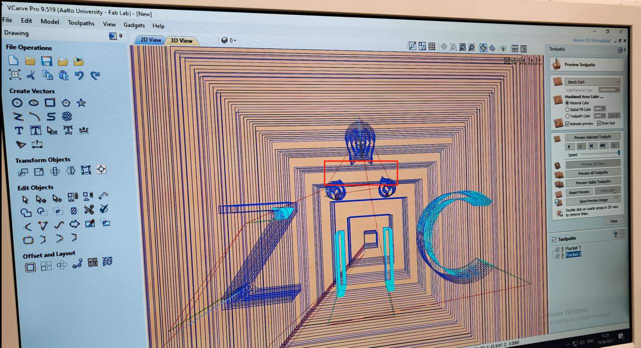
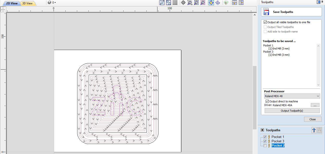
STEP 2 : STEPOVER
- "One of the fundamental parameters of any machining is stepover. It isn't a stretch to say that it is the single most important parameter in determining the quality of the finished parts you will produce. Mostly for 3D toolpaths use ball mills, flat end mills or bull mills. Almost all toolpaths are based on the concept of one toolpath being offset from another by some distance; this offset distance is generally called the stepover. Most software use these toolpath styles - a contour offset toolpath and a raster or zig-zag toolpath (by Robert, May 16, 2011)". I used a contour offset toolpath.
STEP 3 : TOOLTYPE
- I used a flat end tool and for this week more important is be sure how deep the tool could go. For that is necessary to check shoulder, body and overall lengths. For 3mm I set up Cut depths as 1 mm but for 1 mm - 10 mm cut depth.
WORKING PROCESS OF MDX-40 MACHINE
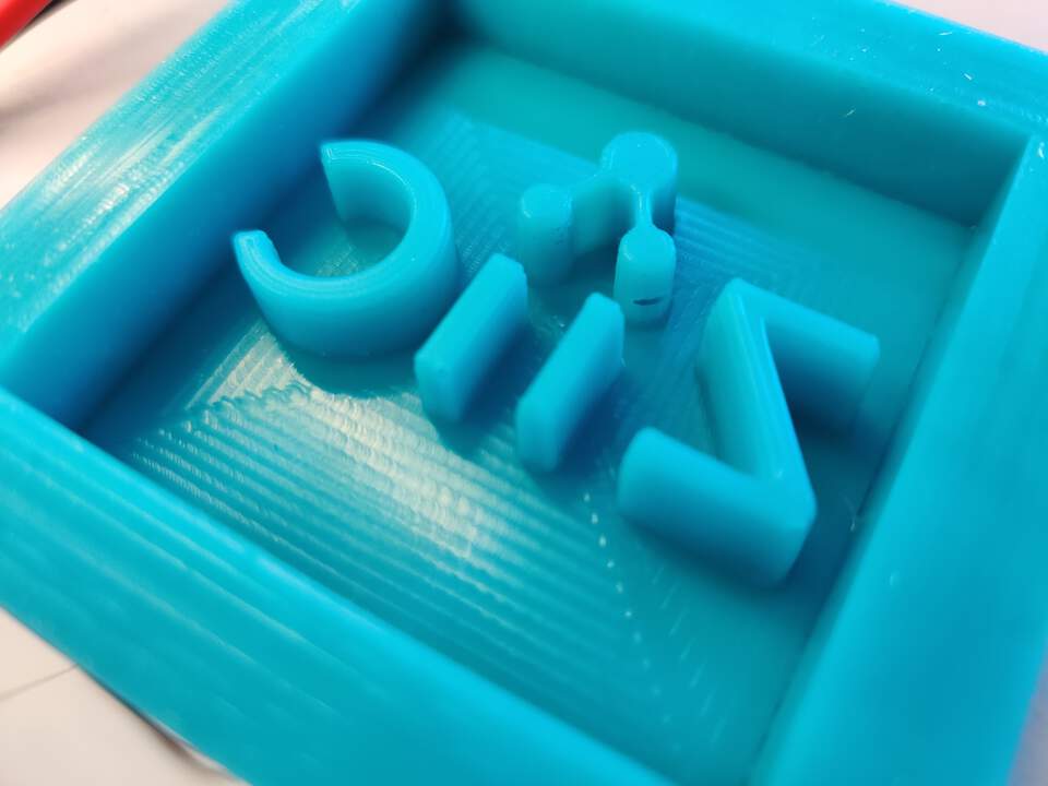
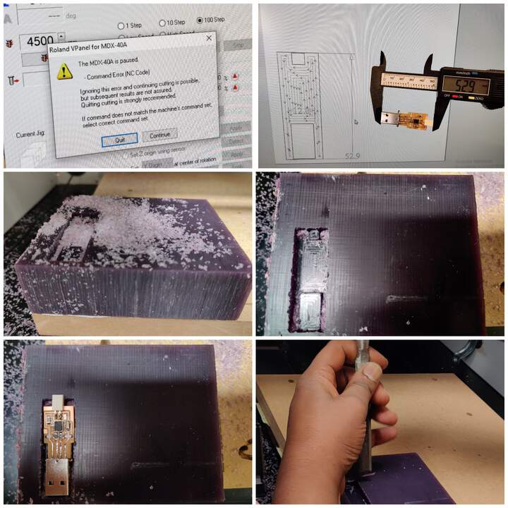
- I used the same wax mold that I used for USB cover (see below) but when the machine had been working for some time, I noticed that it had started milling in the area of the previous model. I stopped the process and prepare the same wax mold but now in other side which wasn't using before.
CASTING PART
STEP 1 : SILICONE RUBBER (NEGATIVE MOLD)
- Silicone rubber what I used comes from Smooth-On vendor, datasheet here.
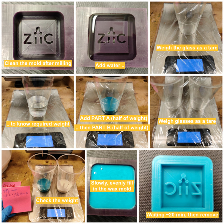
- From the beginning I cleaned the wax mold from milling dirt. To simply determine the amount of substances needed, I filled the wax mold with water. Then I added water to the glass, but before that I weighed the glass itself - it is not included in the weight. I added the first substance in the required amount, then the second. Before mixing the substance together, I made sure that the total weight corresponded to the theoretically calculated. I mixed both substances together - stirring only in a circle. To prevent the formation of bubbles, I placed the mixed substance under a pressure vessel and created a vacuum. Then I filled it all slowly, evenly in a wax mold. After 20 minutes it was numb, but I waited about 40 minutes to be completely safe.
- From time to time, however, small bubbles formed during the solidification process, which I blew up or removed with the tip of a knife.
- After I removed the silicone form I saw that there is a small mistake - a small hole has formed in place of the logo icon.
STEP 2 : LIQUID PLASTIC
- Liquid plastic what I used comes from Smooth-On vendor, datasheet here.
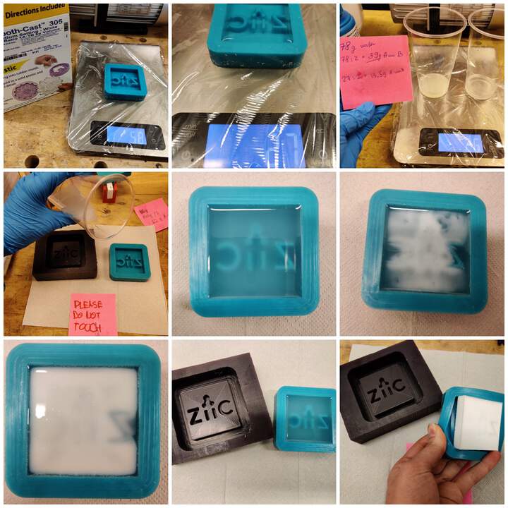
- To make a liquid plastic mold, the process is the same as before, only in this case, to know the weight, it is necessary to use a silicone rubber mold. This mold also hardens quickly, but for complete security I waited longer.
- In this case too I also discovered also a mistake - it may have been necessary to add a little more substance, because now the bottom of the mold shines through a bit and contains a lot of small bubbles.
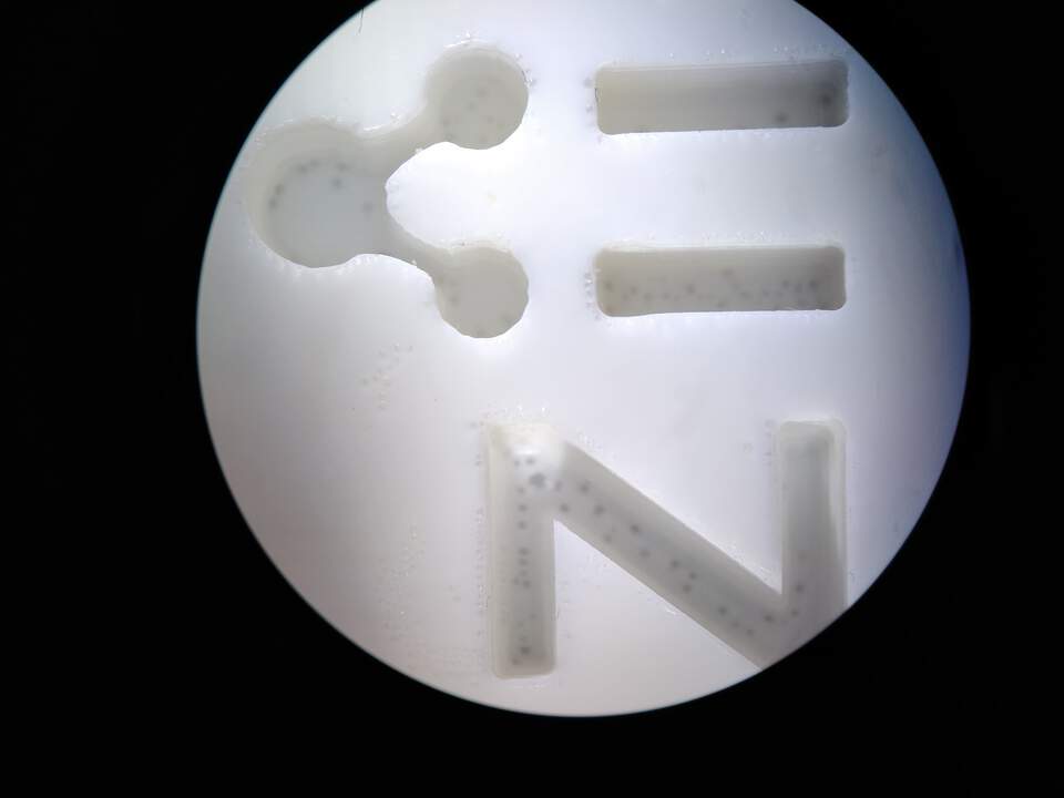
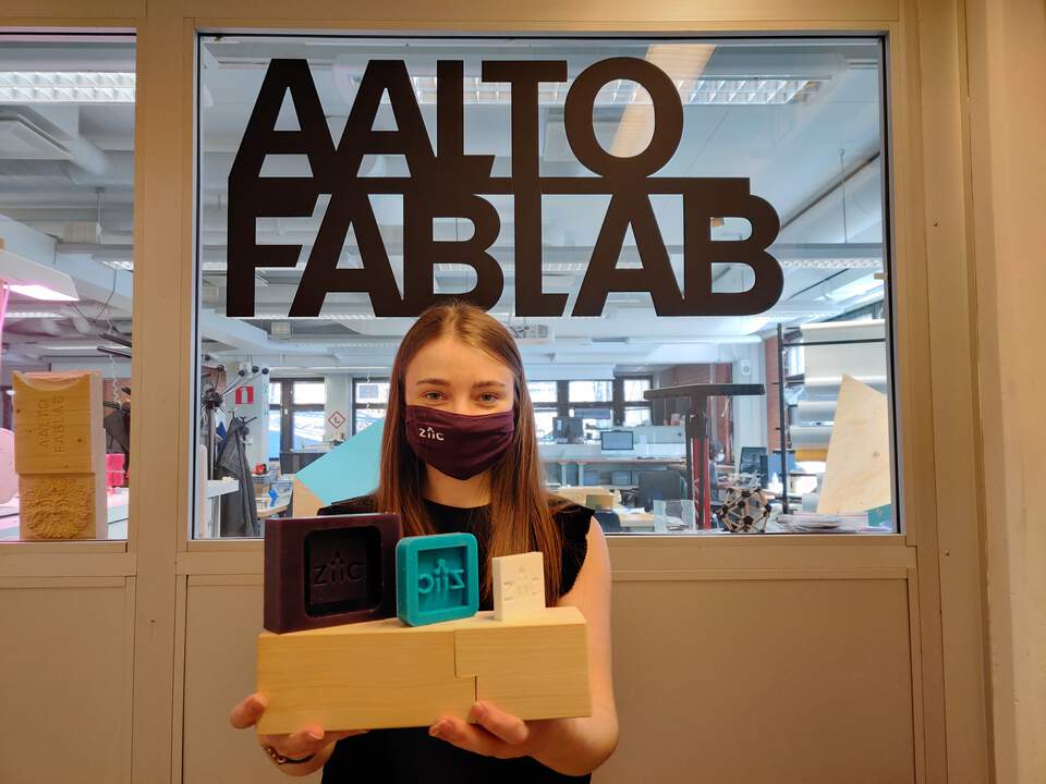
"HERO SHOT" OF THE WEEK
GROUP ASSIGNMENT PART
STEP 1 : SILLICONE RUBBER
- Since each programming week I found that somehow my UPDI board is unsoldering and the short term solution is always to solder the unsoldered place together again. This week I had a great idea on how to create a long-term solution by like an embalming UPDI board. The group members - Solomon and Ranjit agreed to combine the group task with the help for me.
- First of all we measured all dimensions of UPDI board and wax mold. Then we created a model in VCarve Pro and challenged was to make supporting parts. Why did we need supports? Because we don't know chemical processes in casting and we want to protect connectors parts. After that we defined the end mill 3 mm tool and calculated toolpaths.
- After the milling process, we concluded that there were inaccuracies - we could not accurately insert the UPDI board into the wax mold, but since this was not the part we should focus on, we simply manually expanded the support area slightly (the wax mold is good material for that).
- When we tried to add a file for milling in Vpanel, we received an error message - The MDX-40A is paused. Command Error (NC Code). As we later concluded, this was because VCarve generated the NC code, but the .rml file format was set in the V-Panel settings.
- Then we start reading the Smooth-On Mold Star 16 datasheet. Silicone rubbers need mix by volume 1A:1B. Also vacuum degassing isn't required because silicones have relatively low viscosities but since the local introduction lecture showed us how to do it, we also did it just to learn the practice.
- As written on the datasheet, the Pot life is only 6 minutes, we also felt this, because when the two substances are mixed, they start to solidify really quickly - you have to act very quickly. The Cure time is 30 minutes - and we made sure that was the case in real life. About safety - is necessary work in a ventilated area, wear safety glasses, long slooves and rubber gloves to minimize contamination risk.
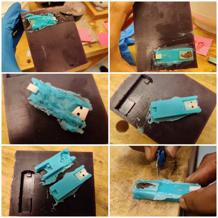
- Silicone rubber part we did twice because the first result was so messy. Second result was much better. But actually this silicone part for us was necessary just for protection because the next step we did in previous positive mold - wax mold.
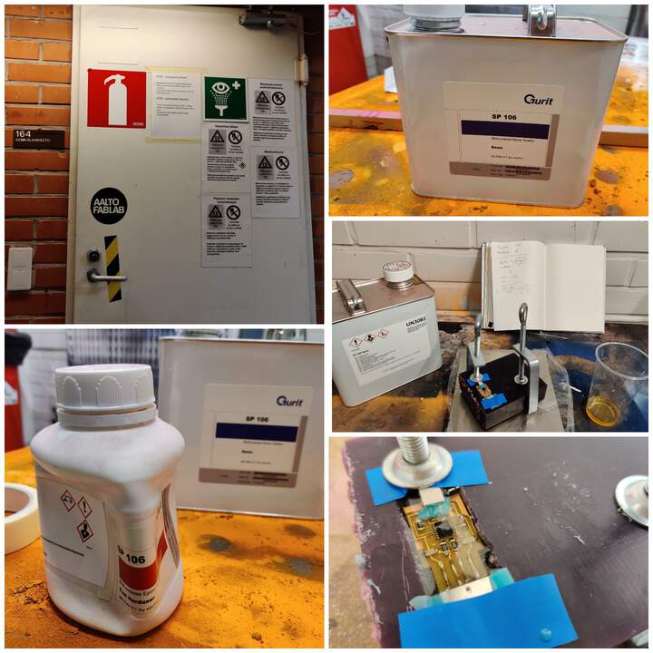
STEP 2 : RESIN & FAST HARDENER
- Work with resin and fast hardener took place in a high precautionary room, where work with hazardous substances usually takes place. Working in safety glasses, long slooves and rubber gloves are mandatory requirements.
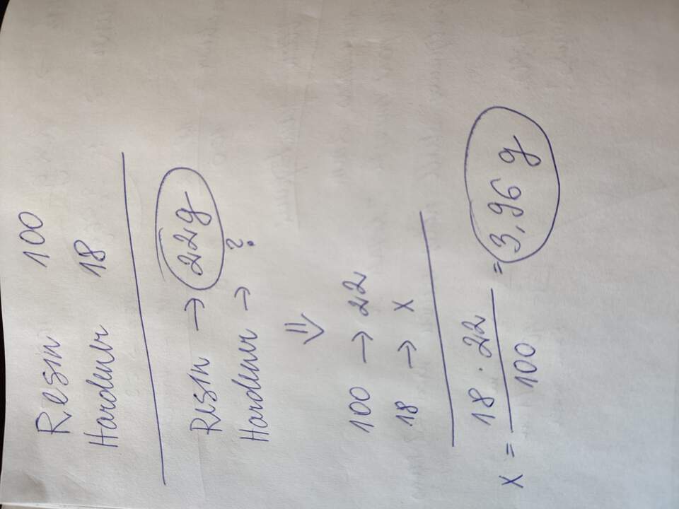
- As written on the datasheet, Resin with fast hardener needs to mix by weight in proportional 100:18. In our case we calculated it like that:
- Unlike the previous steps, it doesn't harden so quickly and we left it on Saturday until Monday morning.
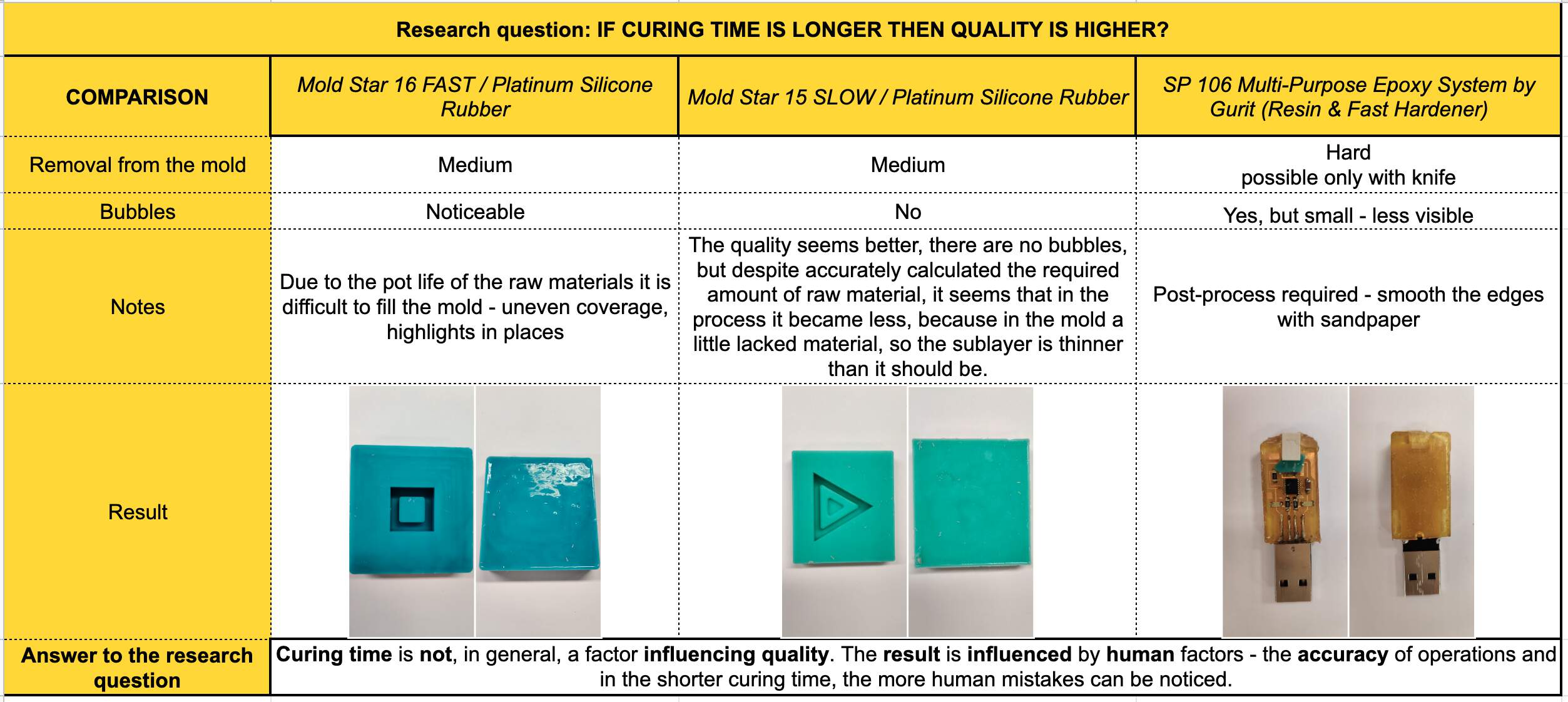
SUMMARY OF DATA SHEETS
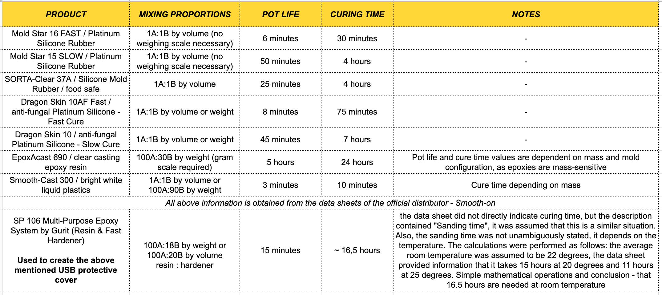
COMPARISION OF MATERIALS