INDIVIDUAL ASSIGNMENT PART
For this week's task, I will use Fusion 360 for 2D design, as well as for preparing a CNC file - creating, setting up toolpaths. I will use Mach3 software for CNC production, which is compatible with the equipment in the laboratory - Recontech 1312. Click to official sites of Fusion 360 and Mach3.
DESIGN PART
- Design I made without any tutorial, but my inspiration was a product of Ariba Box market.
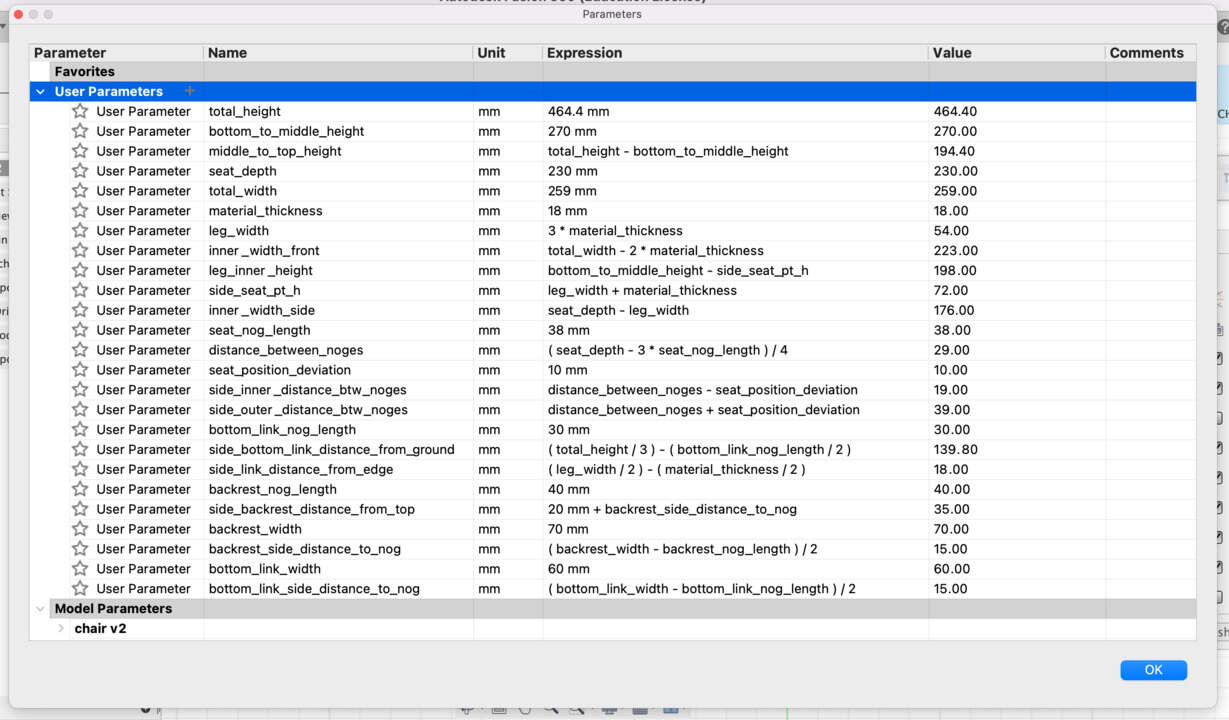
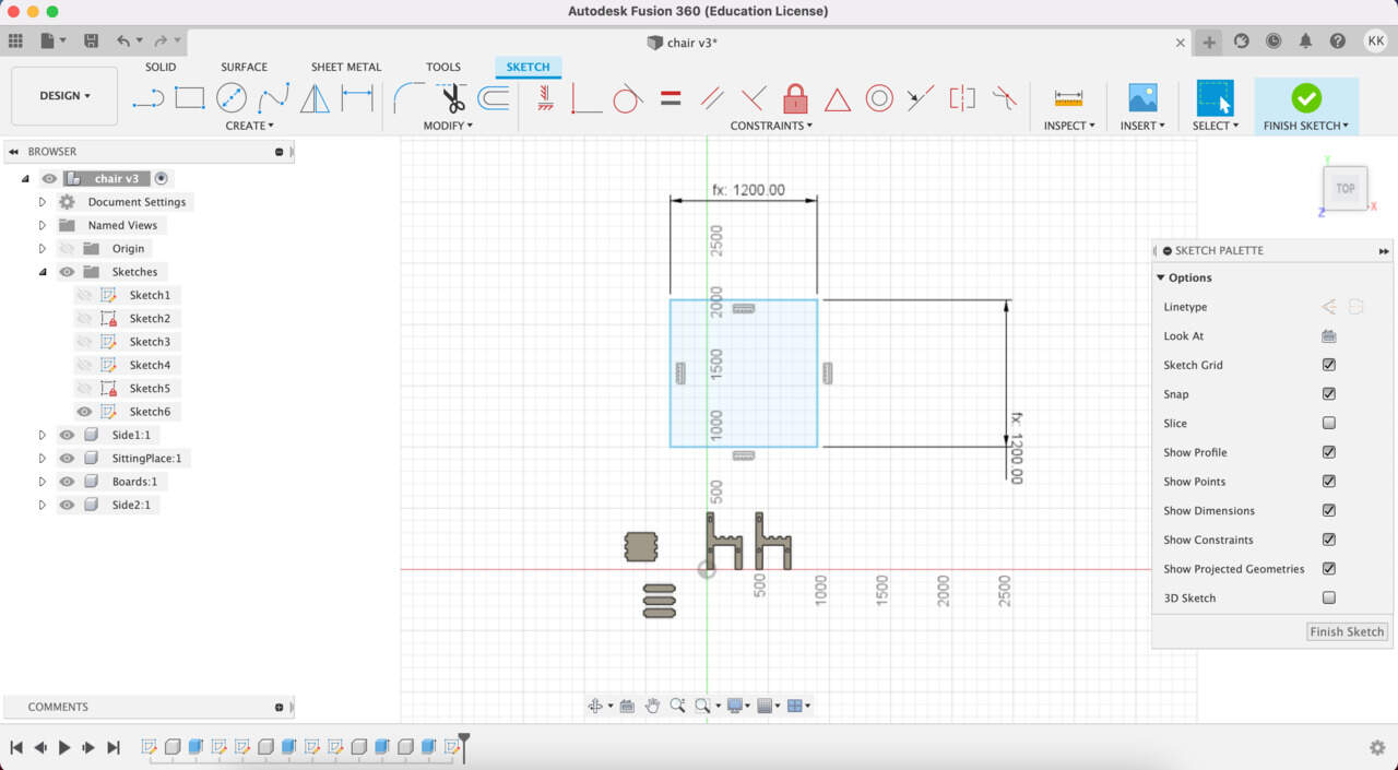
- First of all I define all parameters, for that I spent a lot of time, but trust me - later it really pays off.
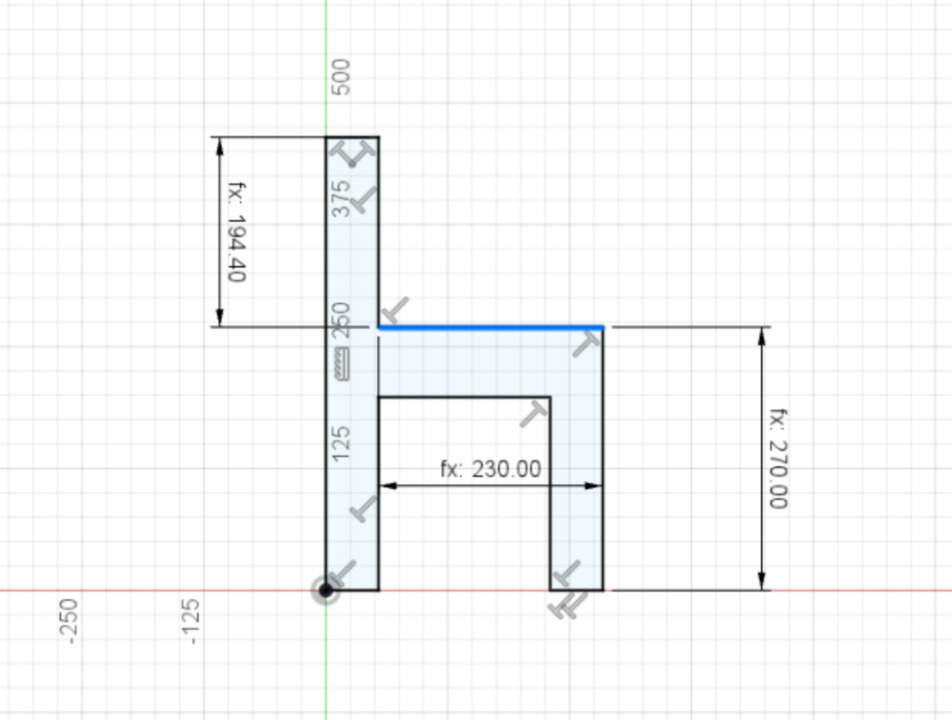
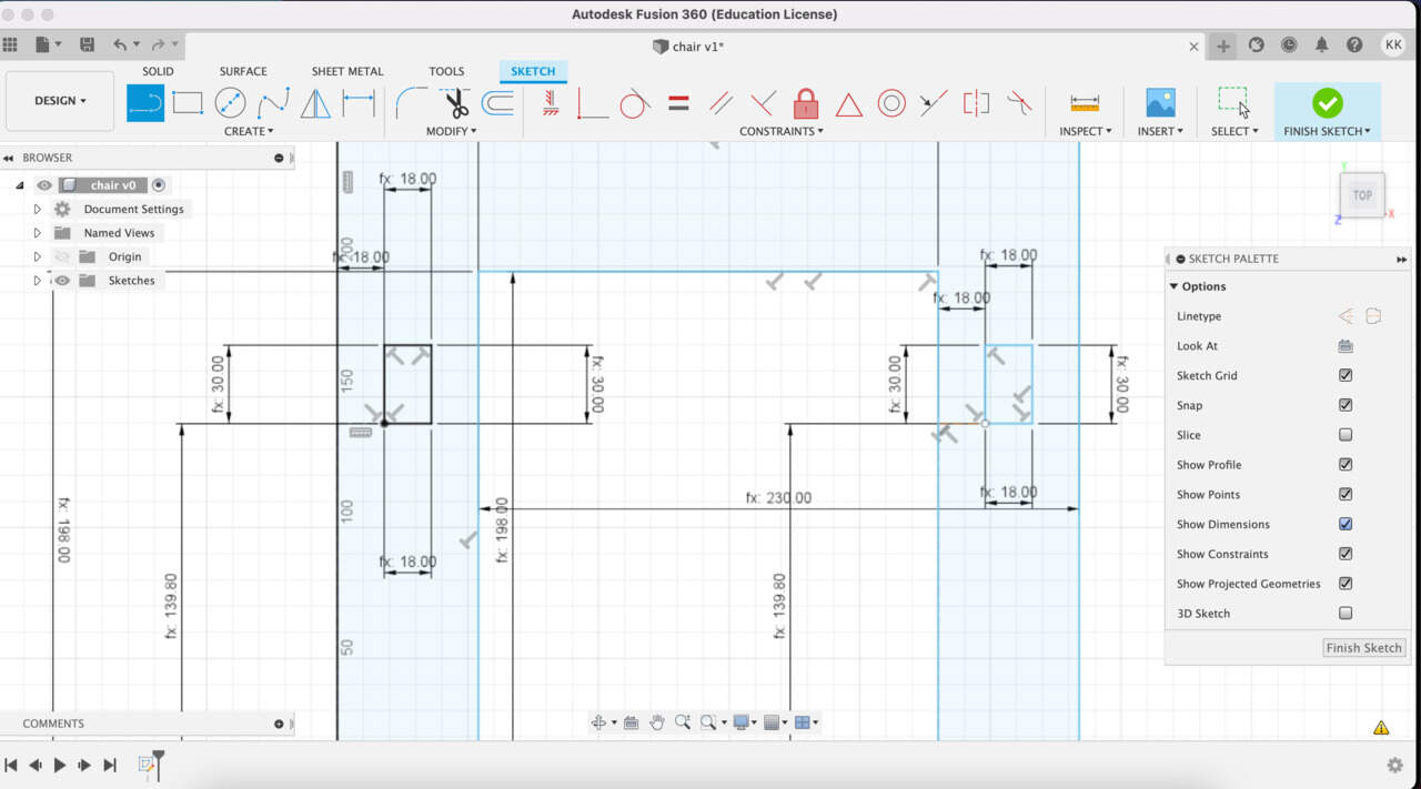
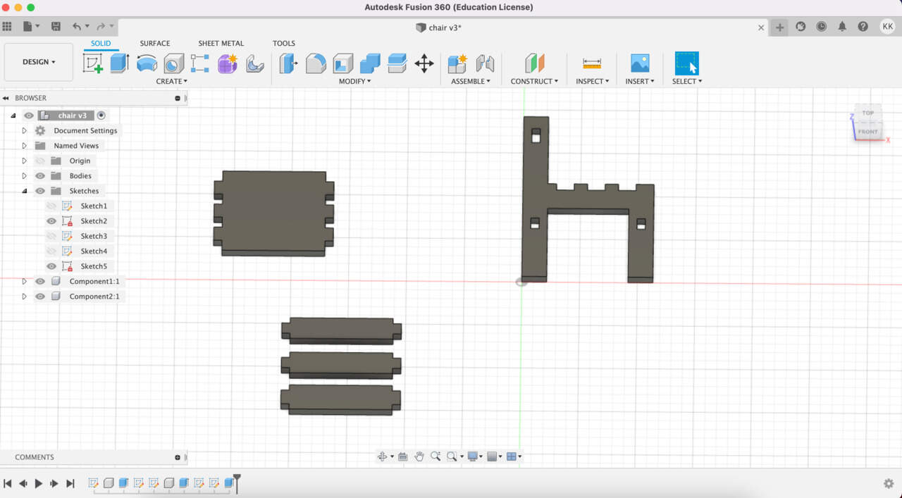
- In Sketch mode I draw all parts of my objects, including connection points. Then I finished Sketch and used the Extrude tool and extruded parts only as much is the thickness of material. Important thing - I don't select connection points for extrude, because I want holes there.
- After I designed all parts of my chair I need add also material as a part for that I create new Sketch and draw Rectangle. Also in this case I used parameters, define XY after I measured precise what is size of material. Then also extrude it as much is the thickness of material. Then choose Assemble tool and make a Joint between top part of object and plane. In Joint settings I select planar as the type and flip it around. Then I made plane like a Ground. Let's do it with the rest of objects. It's important to check that parts isn't too close - I leave a space of more than 5 cm.
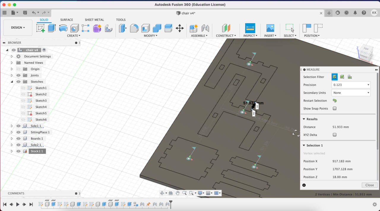
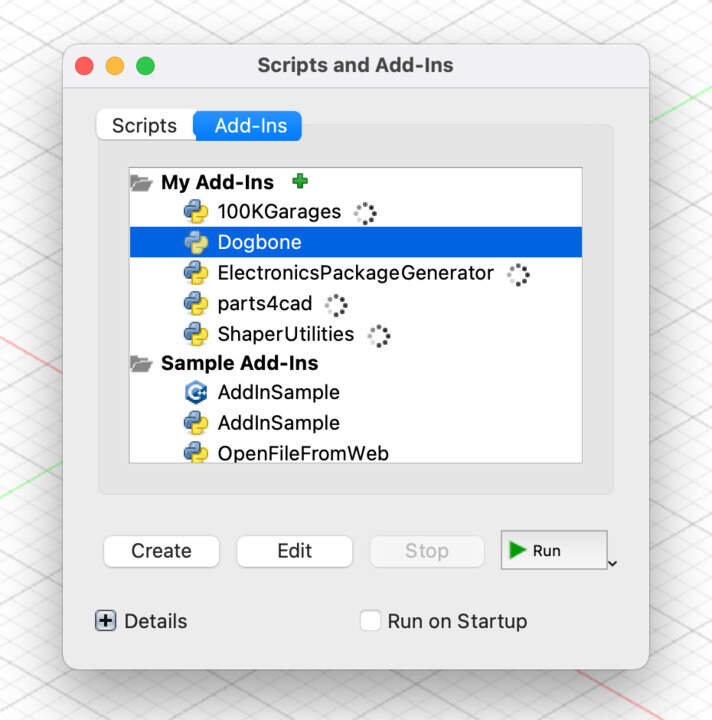
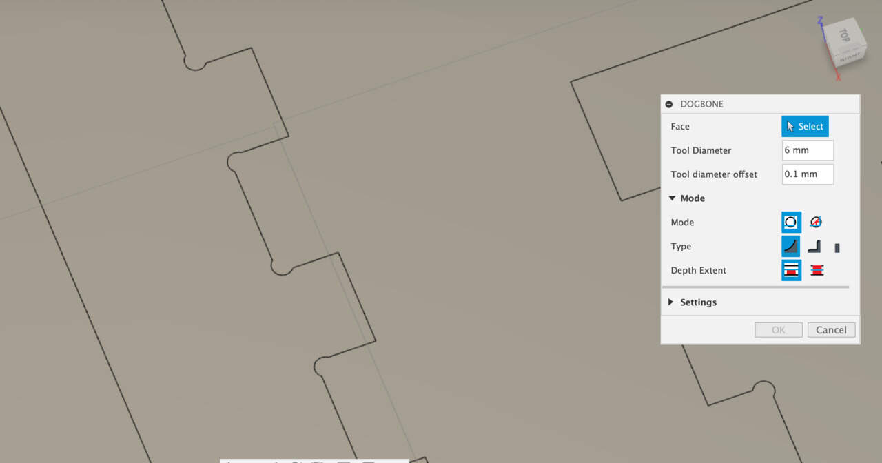
- Before going to Manufacture mode, it's important to add Dog bones. It is needed because the tool is round and it's going to leave fillet. Dog bones give choice to accommodate other parts together. For Dogbones tool it is necessary to install Dog bones plugin (I found it in Github by DVE2000). When it was installed you need to include that in Fusion for that go to Tools section and choose Add-Ins button and upload here this plugin. In order to create dog-bone I hit the upload button in the Solid section and select faces of the objects and it's going to automatically select the edges which have to be dog-boned. For the Tool Diameter I use a shaft diameter, which is 6 mm. For Tool diameter offset I entered 0.1 mm because this gives the tool path generator a little bit more space to get into the narrow areas. Then I choose Static bones, Type - Normal Dogbone. Hit OK and then it automatically creates dogbones.
MANUFACTURE PART
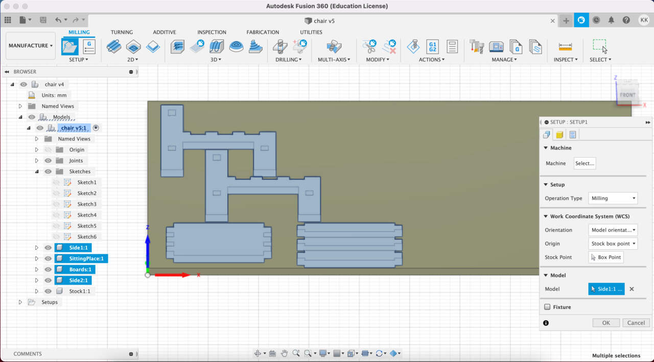
- Milling process starts with creating a Setup - New Setup. For setup you need specify the Stock and I choose From solid mode. Then go to the Setup section and select a point which is going to represent the zero point for the machine. Before hitting OK, select models.
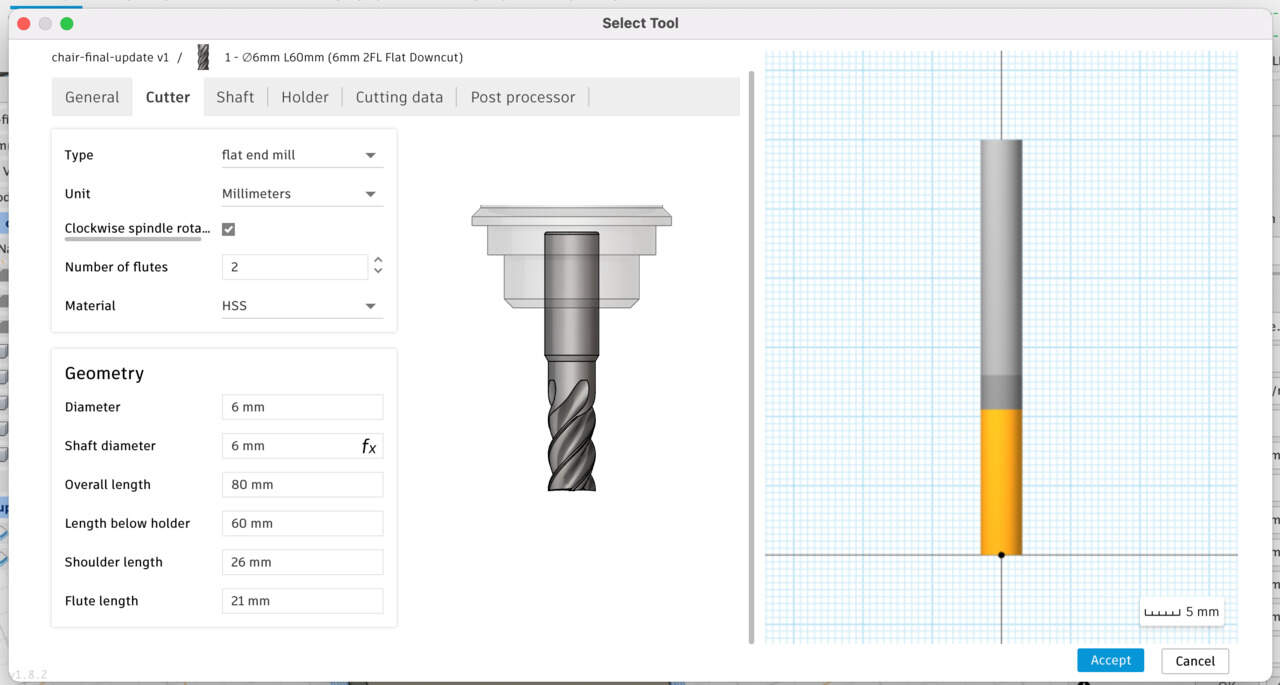
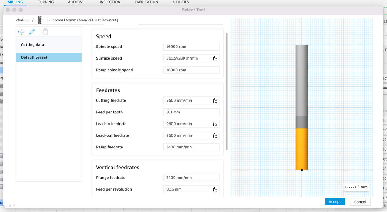
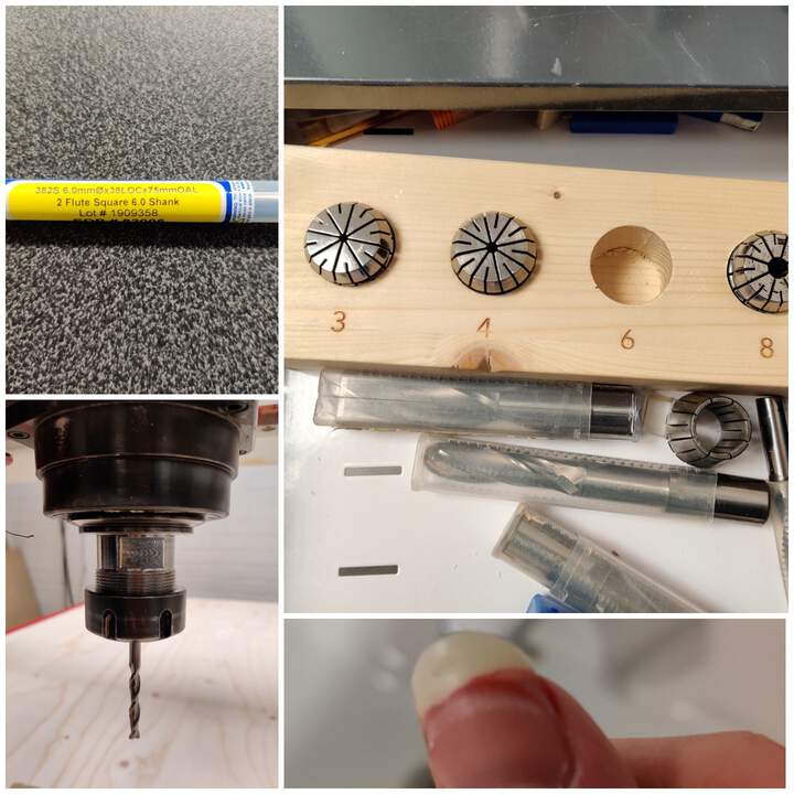
- For the milling strategy I use 2D Contour, in the panel I need to specify all the needed things, first of that is the tool - Select tool. If you do this first, then you need to do it from scratch. Click on the New Mill Tool and specify variables for the tool what you plan to use. Below you can see my variables as I plan to use a 6 mm tool. Important settings is Cutter for Type I choose Flat end mill and it's gonna have 2 flutes, Diameter - 6 mm, shaft diameter also going to be 6 mm, I measured that Overall length is 80 mm, the Body length is how much of this is going to be visible outside of the collet, usually you put it in approx. 2 cm deeps that means Body length is 60 mm - you could potentially something milling in material what is 60 mm thick. The Flute length in my case is 21 mm. I don't have any shoulder so that doesn't matter really but it should be bigger than Flute length.
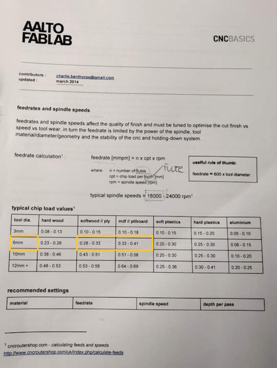
- Then important point is the Feed & Speed section. Important value is Feed per tooth - check in the datasheet it depends of material what you plan to use. As I plan to use something between softwood and MDF, then 0.3 mm is fine. Flutes are the cutters and in 6 mm tools there are 2 flutes that means it's gonna into material two times per revolution. The Spindle speed you can calculate the Cutting feedrate so the Spindle speed is going to be 16000. To calculate Cutting feedrate try this = number of flutes * feed per tooth * spindle speed. In my case it is = 2 * 0.3 * 16000 which is 9600 cutting feedrate. Yes, Fusion does it automatically, but you need to know what happened backstage. Plunge feedrate or plunging is when tool goes down so for Feed per revolution usually you can write one half of Feed per tooth. In this case - 0.15 mm. That's it.
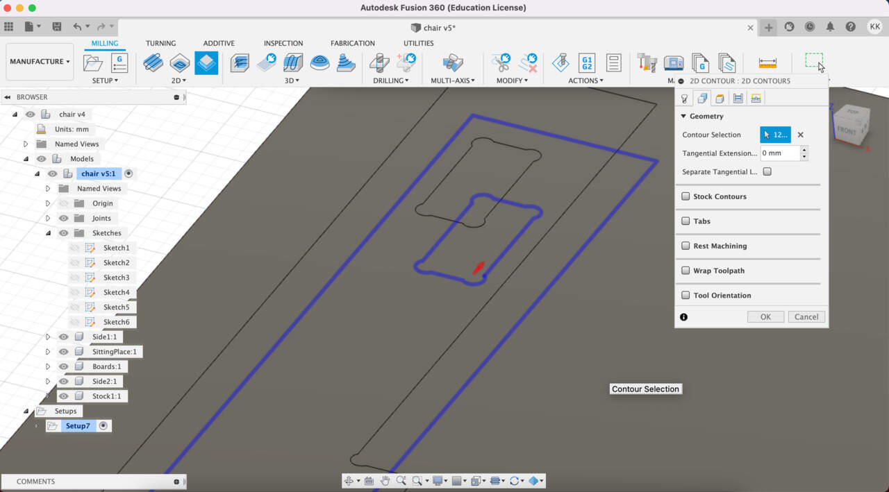
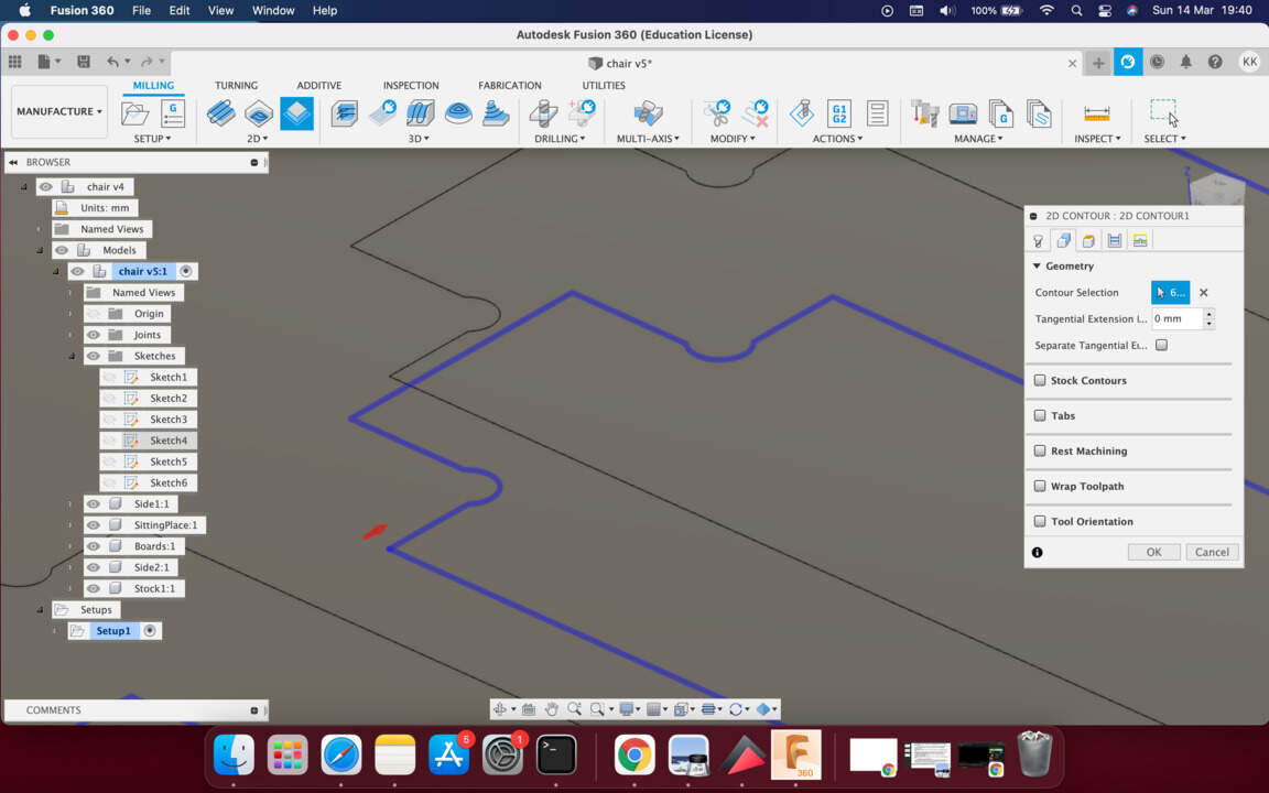
- Next step is to select Geometry what you want to cut and you should always select the bottom line that you want the tool to cut around. Another thing is to check where a little arrow is. It needs to be outside, but for pockets - inside.
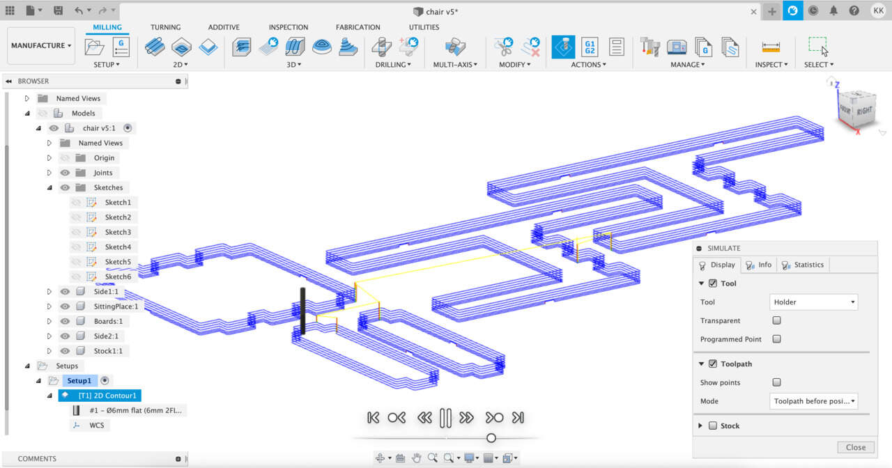
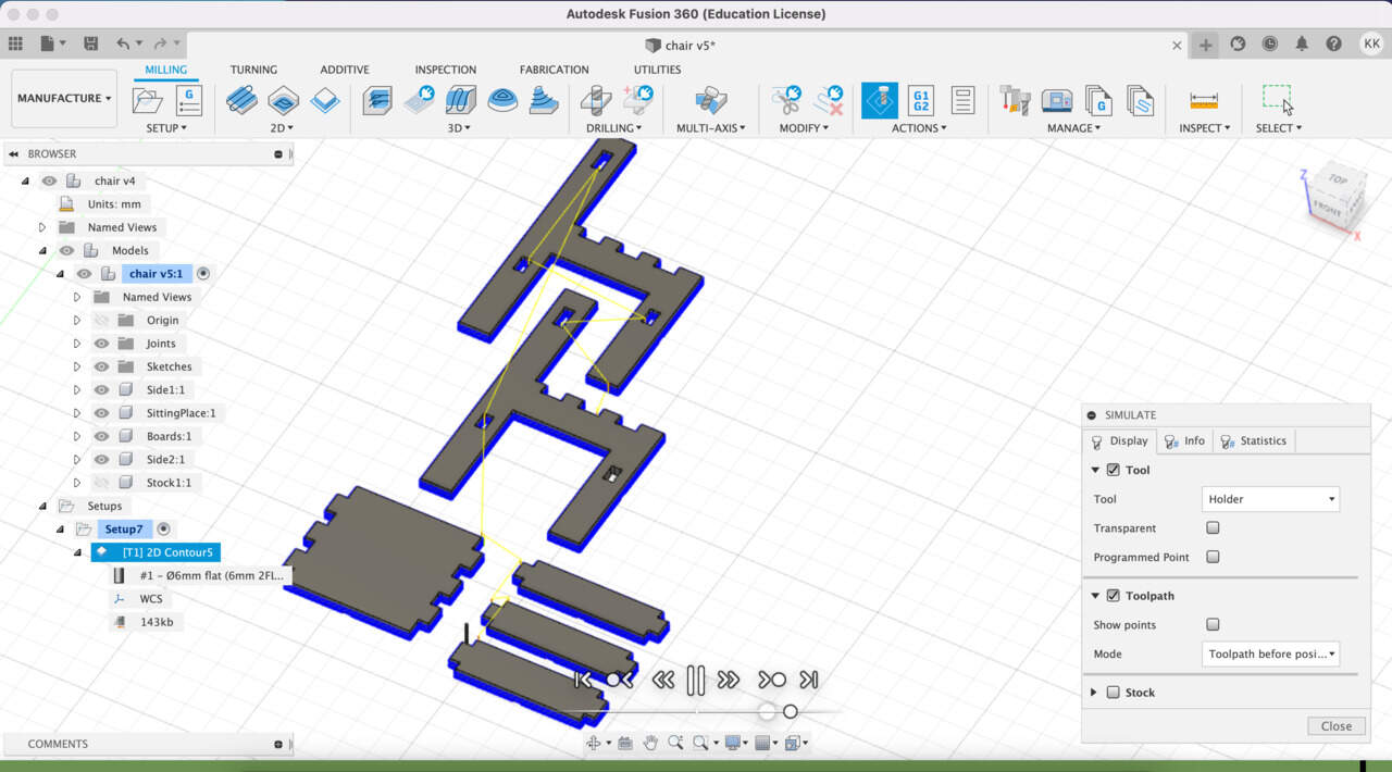
- Then you need to enable Multiple Depths to set a Stepdown - this is how deep the tool will go per pass, it should be not more than the diameter of the tools - I write half of the tools diameter 3 mm. Then hit OK and these blue lines are toolpaths. Then you can Simulate the process. When you're done you need to export for that select Post Process and for Recontech1312 I choose Post processor type - Mach3Mill / mach3mill option.
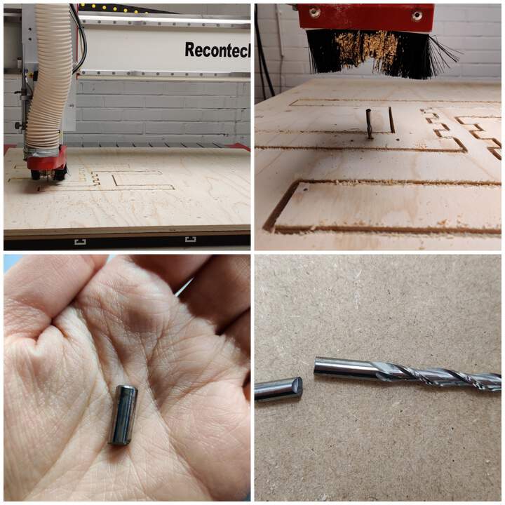
CNC MACHINE RECONTECH 1312 SETUP
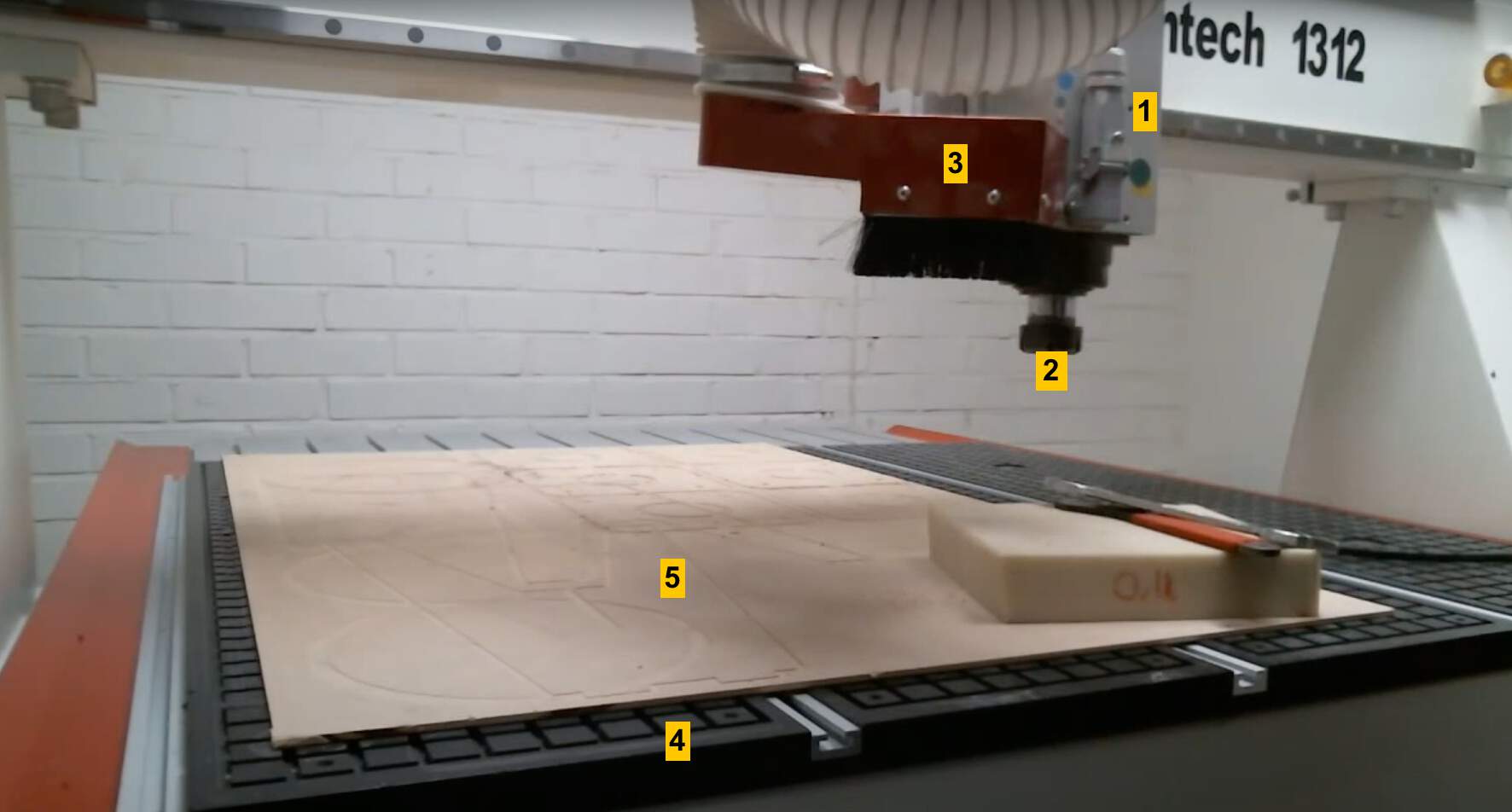
- It's a three axis machine. (1) is the spindle, (2) there you can install the tool, (3) there is a dust extractor so you after mounting the tool you hook update extractor and it helps you to remove dust after jobs. (4) This is a vacuum bed which is capable of pulling the material downwards so even though it has for robbery bed where you can place your material so when you're cutting through the material you don't want to cut into that. (5)This is the reason why you also need to use a sacrificial layer (in this case it's MDF material.).
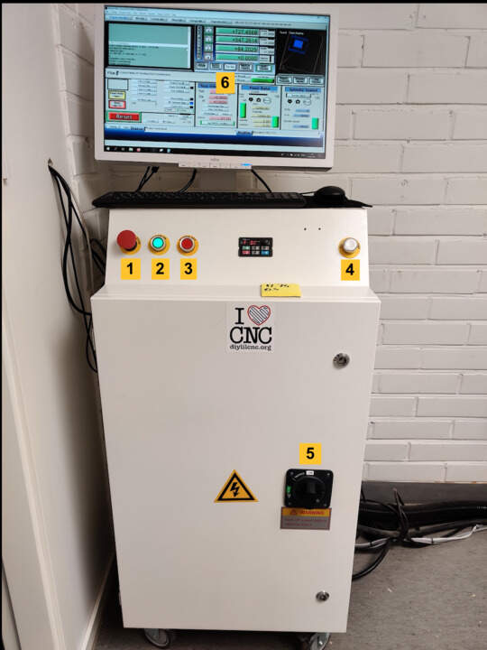
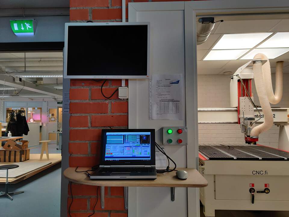
- In the picture you can see CNC computer station, there are some buttons - the emergency stop button on the left side, green power button, power off, and on the right side vacuum pump ON/OFF button and below - switch what you need to use first in order to turn it on. Then press the green on button and wait for ~15 sec, because the computer what is inside wants to establish a network connection with the computer on top of it. When that is done you can open Mach3 software, you should be in the administrator role. When it's open you can see Mach3 machine control software.
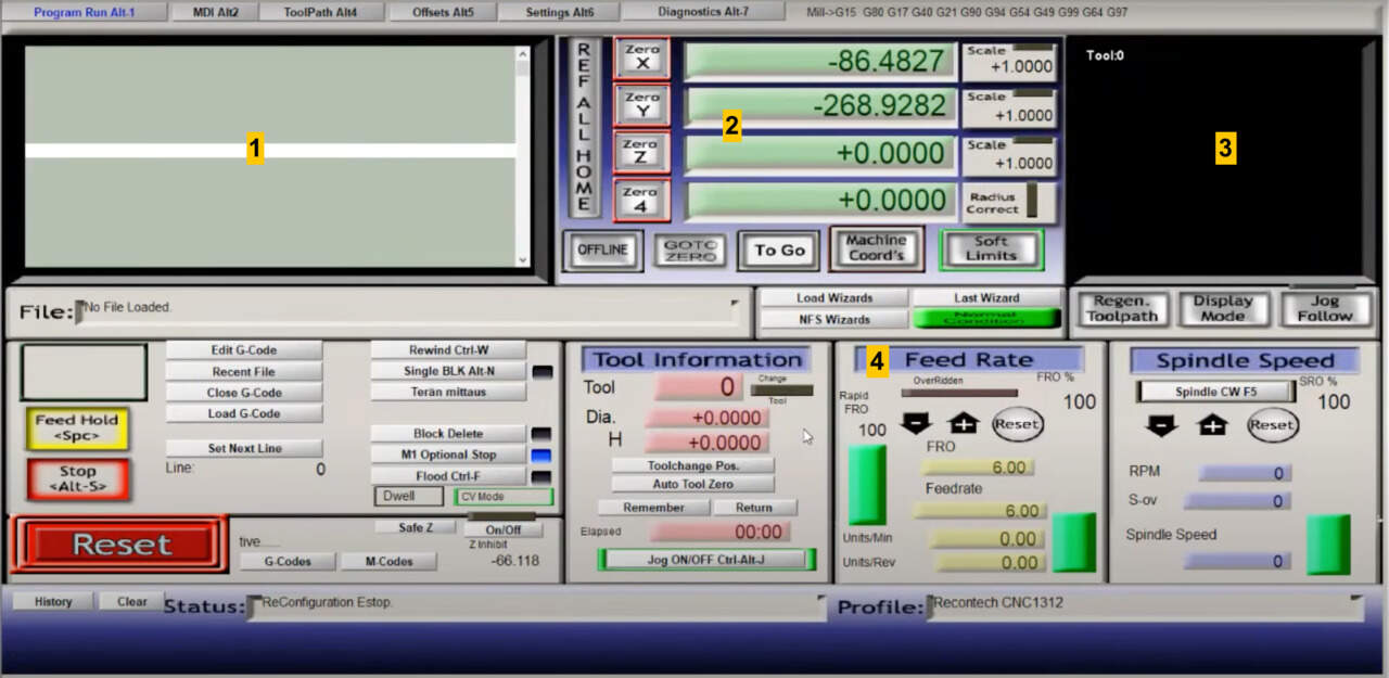
- (1) Here you will see the G-code when you load it. (2) here you can see the XYZ coordinates of the tool that is moving around. (3) and on the right side when you load the toolpath then you can see a preview of that. (4) The Feed Rate section sometimes is very useful, for example, if you're not sure whether you set the feed rates right then you can manipulate in the software.
- Hit blinking Reset button in the software, then you need to check whether the Soft Limits are ON, because it might be in grey color and then just click on them and it become green.
- Hit the Reference home button which is going to move the machine to its machine zero positions. This is why Soft Limits are important because it doesn't have any hardware switches so you need to specify that it internally has to software wise detect where it is at the moment so otherwise it can happen that it just falls off the table.
- Use arrows buttons in order to move it around. If you hit and hold shift and then use the arrow button, then it moves faster. In order to move the tool down - up for that you need to use Page down - Page up buttons.
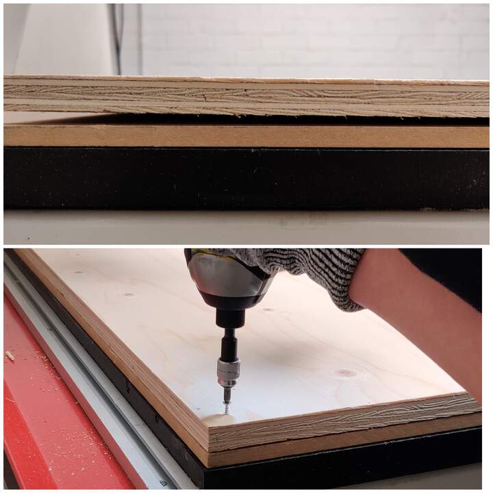
- Below sacrificial layer you can see open holes - you need open holes only as much where the material covers them. Also you can see rubber bands, then you need to put around the material's edges. Then I was ready put my material(❗don't forget below real material put sacrificial layer) and to activate the vacuum pump, but before do that ❗don't forget about safety recommendation - use headphones. Weared the headphones? Then you can push the vacuum pump button.
- Then I realized that material doesn't move, but I see the problem - between the sacrificial layer and real material there is a little space. SOLUTION? My instructor Kris suggest me to screw the material. If you do that you need to know that in this case pressure level could be a little less then actually for pressure is enough.
- Next thing is about collets. Collets for each shaft size there's a different as I plan to use a 6mm shaft, I choose a 6mm collet. Then setting up the tool.❗Be careful when you insert the collet - in picture you can see that I did something wrong! Anyway you need to be sure that the collet ends up being flat with the bottom.
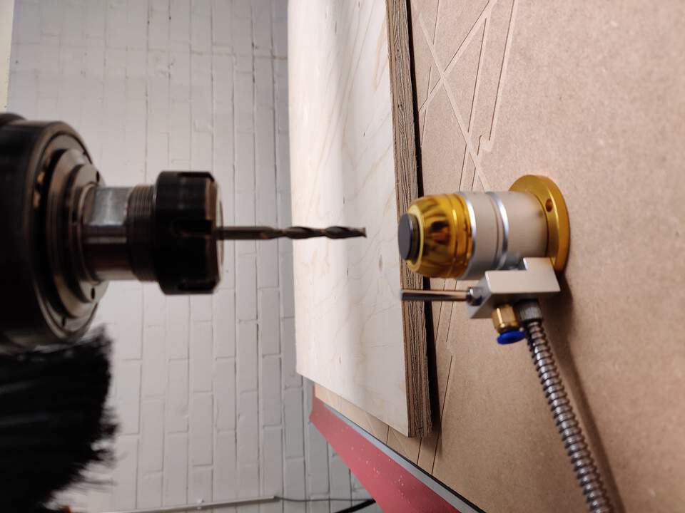
- In Fusion360 I set the origin to the bottom of the material to the left closest corner in order to set Z properly you need to move the material a little bit (Ups, in my case I need remove the screws). Anyway you need to use the sensor and you also will need to activate the vacuum pump because the Z is going to change when the vacuum is going to be operating. So when the vacuum is on it's pulling the material down and you can lose a millimeter or fraction of a millimeter. Before activating the vacuum pump move the tool closer - try the position to tool as close as possible to the sensor. To detect sensor activate button (in this software it's called in 🇫🇮 Finnish like Terän mittaus). Push the button and it sets Z in zero.
- Then set XY positions - use the keyboard so going to try to move the tool closer to the material. After that hit Zero X, Zero Y buttons.
- Then install the extractor. ❗Be careful - don't break the shaft.
- Activate the vacuum pump and go out of the room. Next to the door have two buttons - when the green light is on that means that the spindle is up and it's safe. When the red light is on it means it's going to start running job when it's loaded. ❗Whenever you open the door during the milling process the software receives a signal that spindle should stop. If you see that something is going wrong and you don't want to stop the job then don't open the door because when you open the door - everything immediately stops and you lose all your setups before (include X,Y,Z position)!
- In the Mach3 software click on the Load G-Code button. When it uploads in preview you can see your toolpaths. If all seems correct, press the physical green button.
- Fusion 360 told me that for cutting my objects it will need 5 minutes. When it started to cut the sides of my chair some seconds I felt relieved, but these feelings came too fast! It cuts sides parts good, but my fault - in Fusion360 I didn't define that pockets need to be cut FIRST! But all not so bad, the tool broke right - I can use it again, because most important parts work.
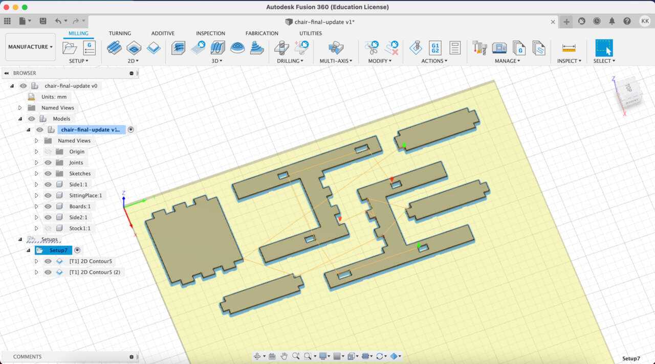
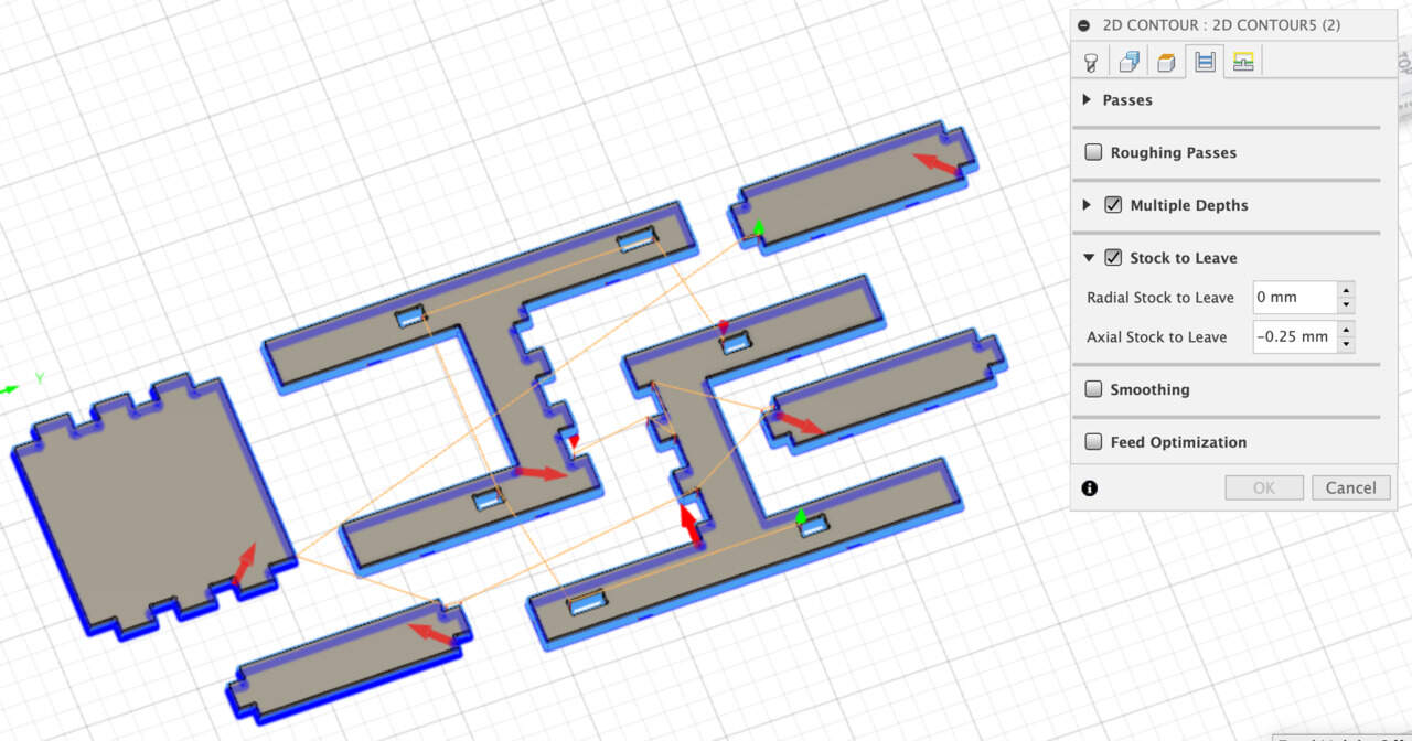
- In Fusion360 I changed in Manufacture mode - Setups - create two Contours setups.
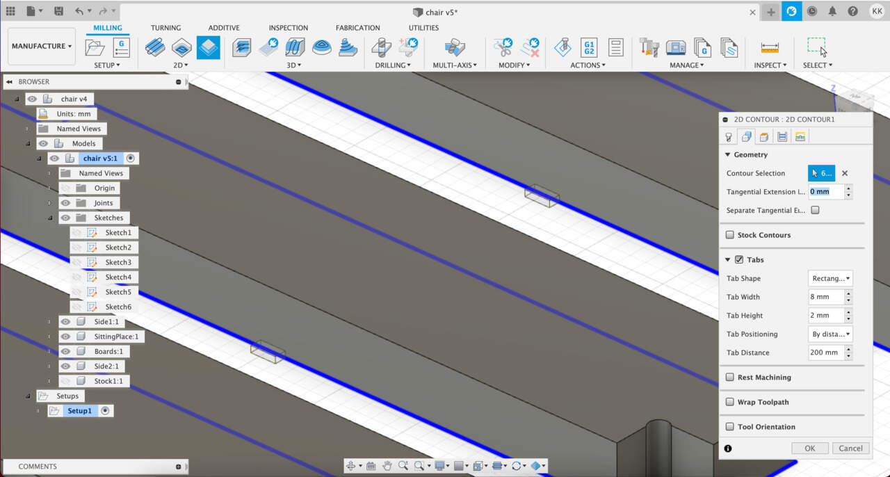
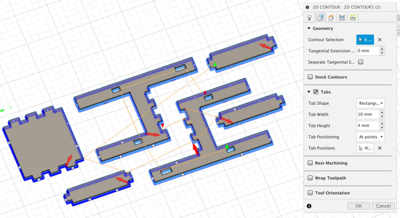
- I use Tabs, but before I broke the tool I see that sides in finally steps start to move, it means that something not so good with Tabs values. I changed Tab Width from 8mm to 10 mm, Tab Height from 2 mm to 4 mm and added some tabs manually.
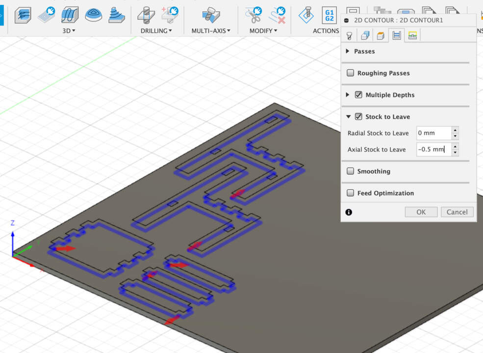
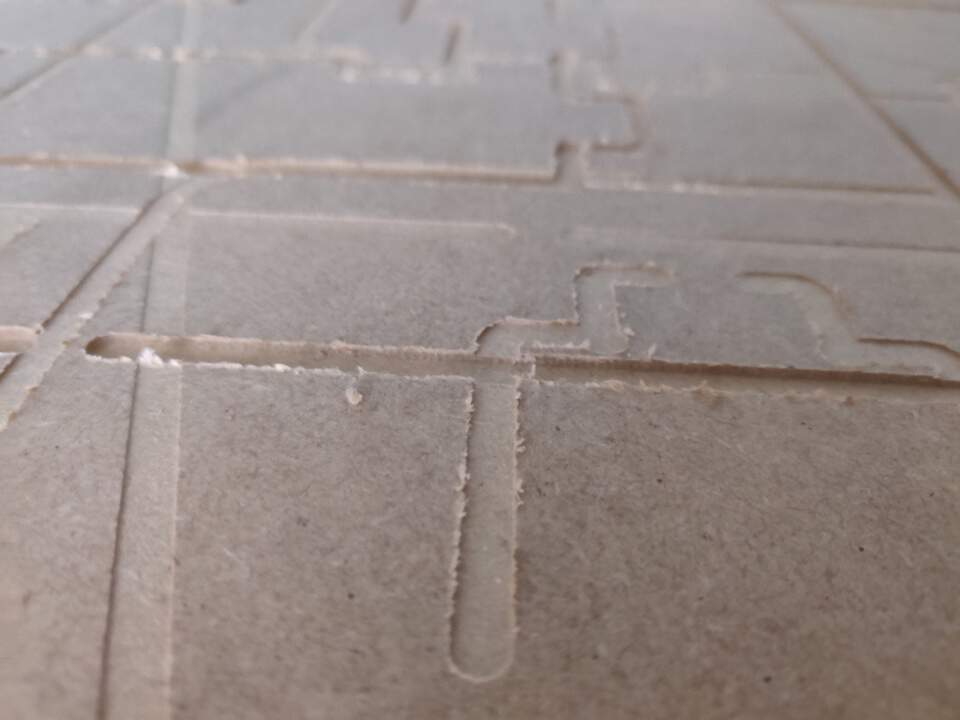
- In the sacrificial layer I can see that tool cut a little too deep for that I changed Axial Stock to Leave from -0.5 mm to -0.25 mm and measured again thickness of material and I realized that I need precise from 18 mm to 17.7 mm.
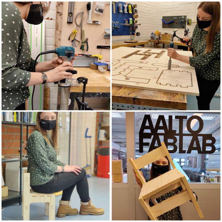
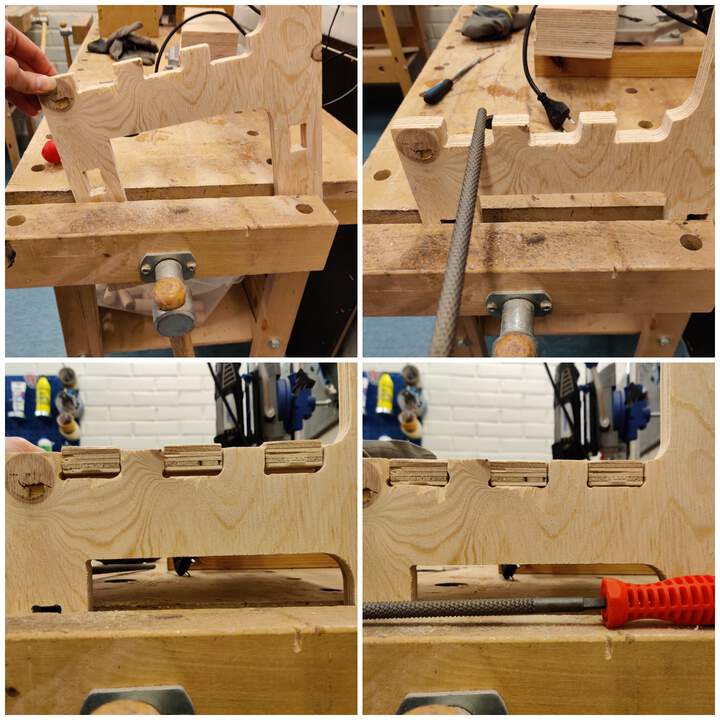
- When I assembled all of my parts I saw one thing - one of the sides doesn't have a DogBone, but most interesting is that in design it IS! I don't know where it would be a problem, but maybe when I create changes in other parts it would be good if I create DogBone again (not just save updated file). Anyway I need to do something for a solution, it's not so fun if you need to sit on a skewed chair. Woodworking place saved me - I used a round crown tool and made a DogBone manually. It works!
THREE THINGS WHAT YOU NEED TO DO BEFORE YOU START DOING ANYTHING ELSE WITH MACHINE:
MATERIAL SETUP:
SET CALIBRATION:
START JOB:
WOODWORKING PART & RESULT
FUNNIEST PART - ISSUES!
WHAT ELSE I UPDATED AFTER MY FAILED?
GROUP ASSIGNMENT PART
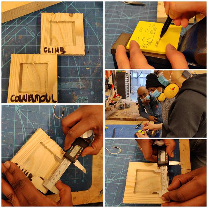
- Climb vs Conventional Milling results were pretty close - with the Climb we were at 59.99mm and with conventional it was 59.98 mm. Milling Tools can advance through material, so that the cutting flutes can engage the material at maximum thickness and then decrease to zero. This is called Climb Milling. Cutting in the opposite direction causes the tool to scoop up the material, starting at zero thickness and increasing to maximum. This is called Conventional Milling. It is hard to imagine what the difference really is - one from thick to zero, and other from zero to thick. I try to imagine this as a scooping of ice cream - you scoop it one way, you get a certain result and opposite way, it is slightly different. Conventional milling apparently causes the tool to rub against the cutting surface, generating heat and causing more tool wear. Also apparently can lead to a poorer finish. So it goes that unless specifically recommended by the manufacturer, climb milling is recommended. We can however see the results below.
- Other things I explained at the individual assignment part.