2D design
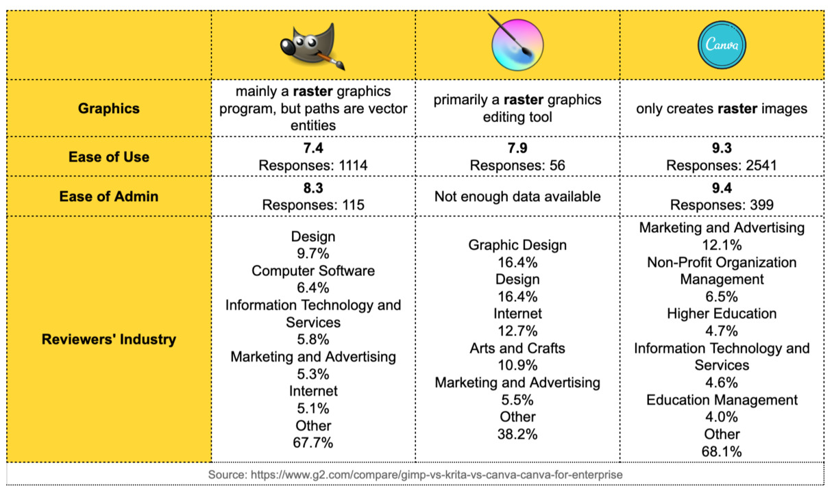
COMPARING GIMP & KRITA & CANVA

- My inspiration - GIMP Tutorial: Put Someone's Face on an Object. (youtube)
STEP 1 : OPEN, CUSTOMIZE SIZE, MERGE
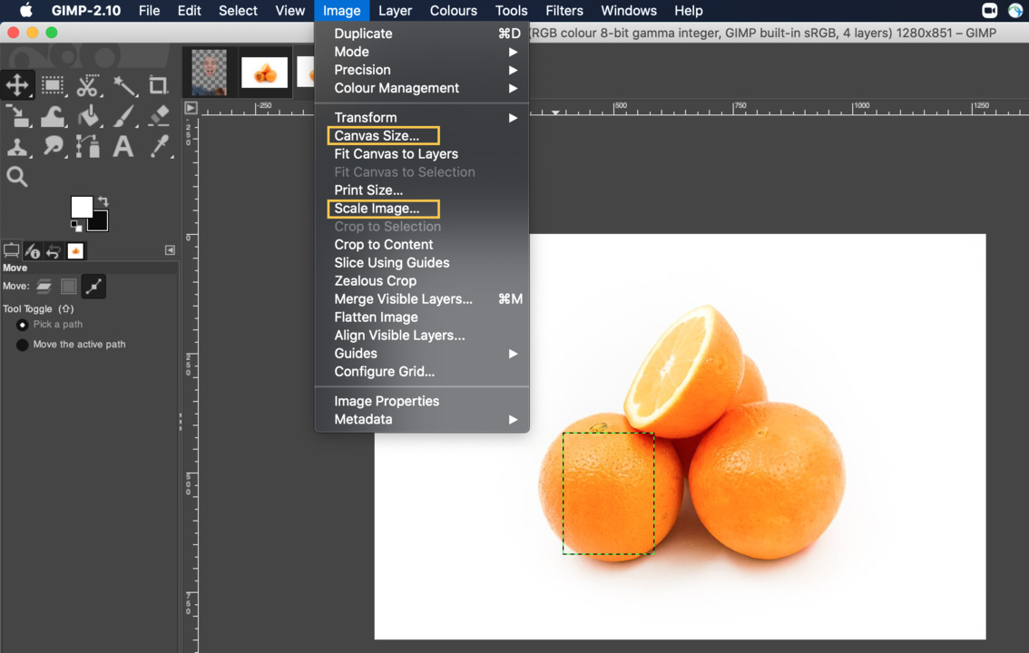
- Open images with GIMP.
- ❗ Remember, for this step you need install GIMP before.
- I tried make something fun with GIMP and .. the first challenge faced by me is different images size and how to customize canva size.
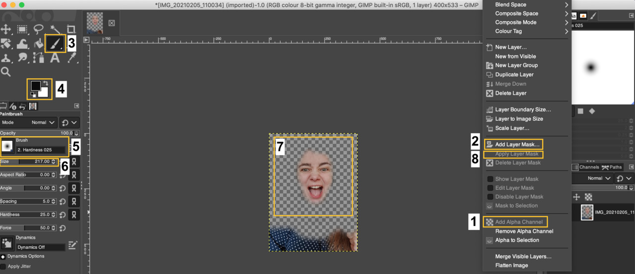
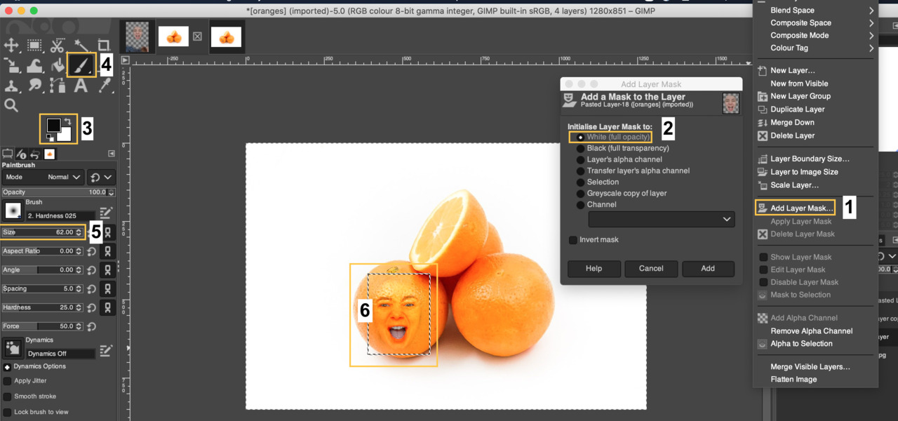
- Add Alpha Channel, then Add Layer Mask - white (full opacity), choose Paintbrush tool, exchange foreground color to black and background - white, choose Brush Hardness - 025 ,then choose Brush size and marked face the cropped face zone.
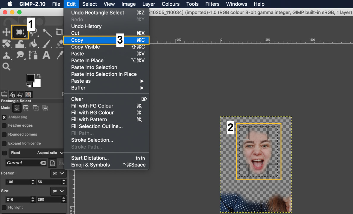
- Choose Rectangle Select Tool, then marked face and click on Edit - Copy
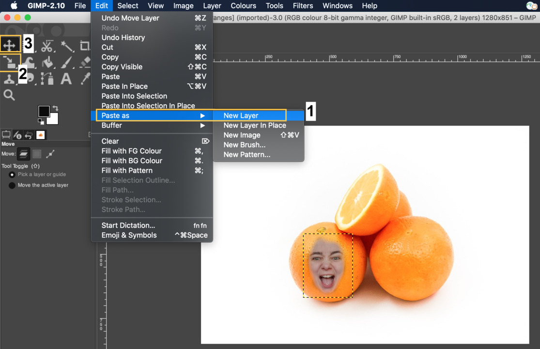
- Click on Paste as - New Layer, then choose Scale Tool and customize size, then with Move Tool put image where you want integrate it.
- After that duplicate layers and change mode.
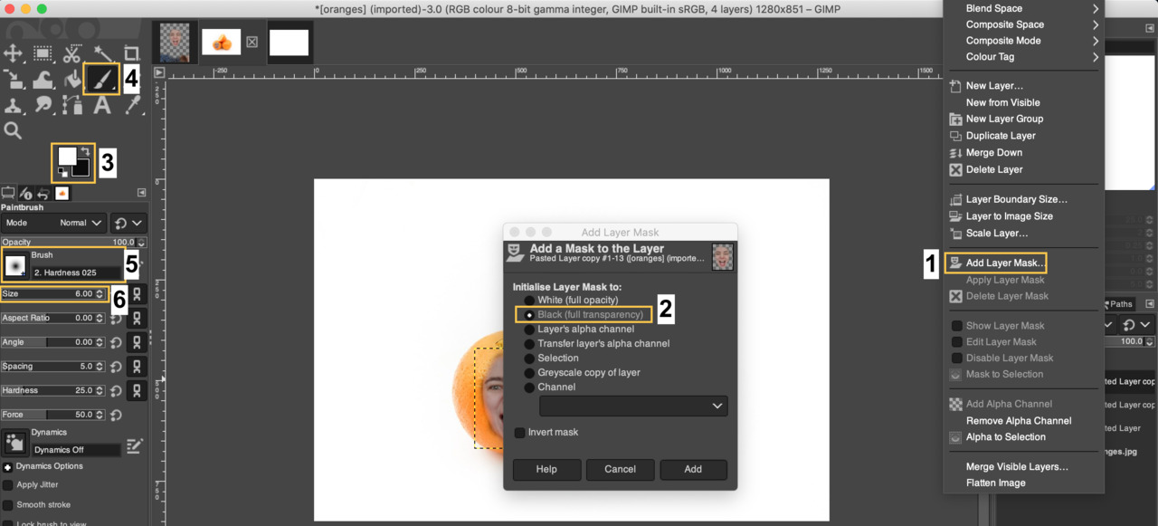
- Add Layer Mask - black (full opacity), exchange foreground color to white and background - black choose Paintbrush tool, then choose Brush Hardness - 025 and then choose Brush small size.
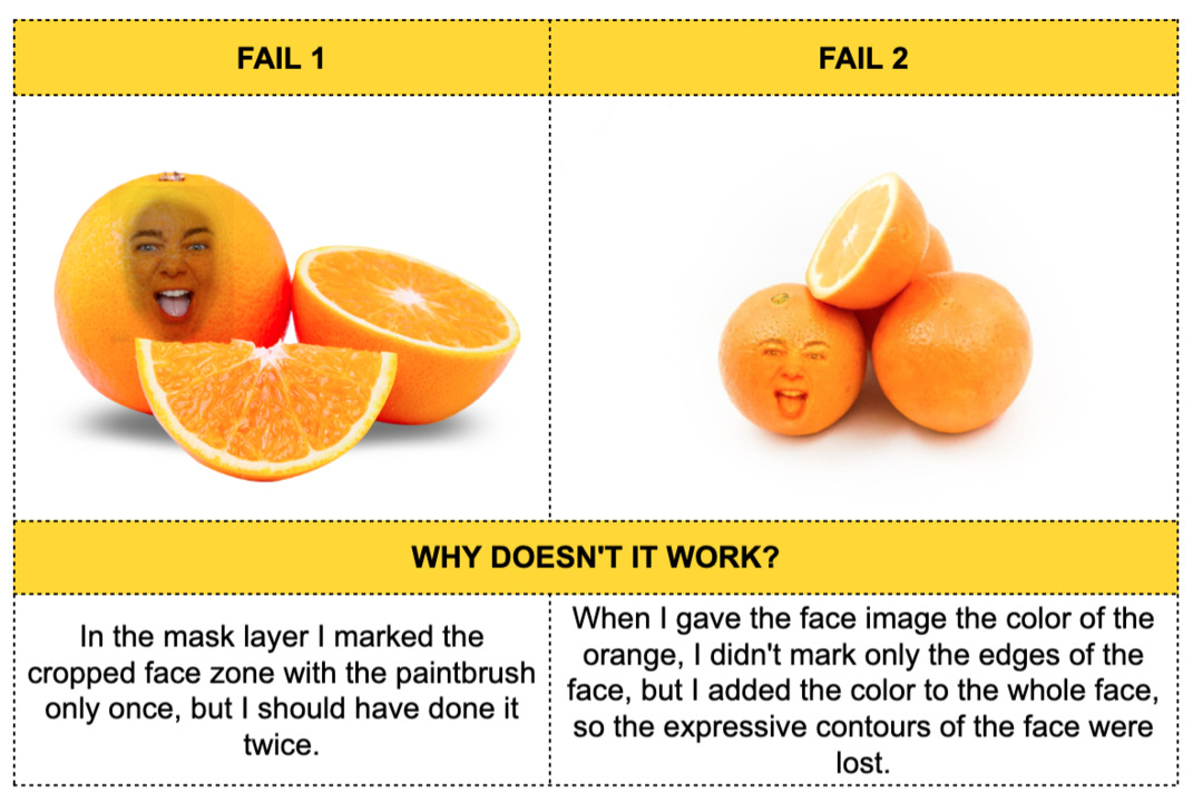
- Mark the eyes and mouth zones. (Now, you understand trick with very white teeth?)
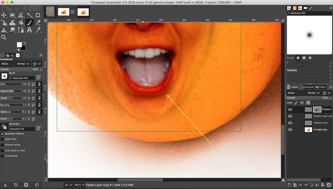
- Add Layer Mask - white (full opacity), exchange foreground color to black and background - white choose Paintbrush tool, then choose Brush size and mark the edges of the face.
- Conclusion - this not related with my final project, but this exercise very good explained to understand how works layers in GIMP.
- My inspiration - Fusion 360 tutorial - Noozle storage box. (youtube)
- Create sketch (XY plane), then create Central Rectangle (60x120mm) and then click - finish sketch.
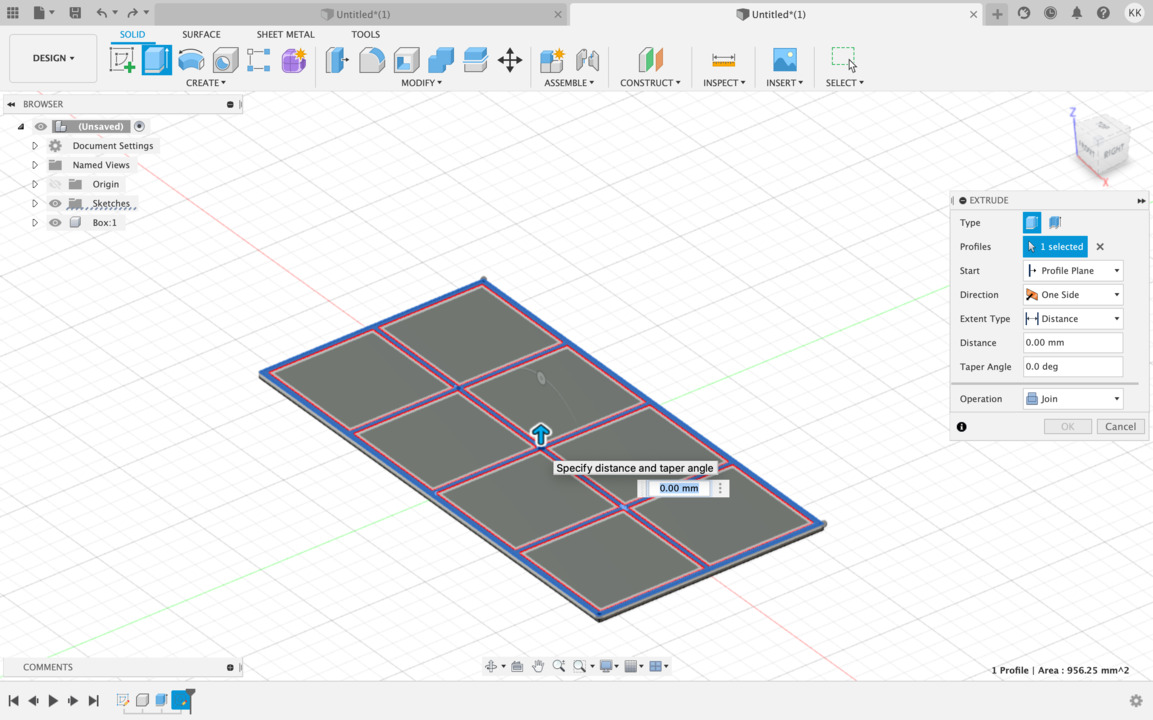
- Extrude sketch 1.5 mm and choose Operation - New Component. Rename Component name to "Box".
- Choose top face of component and press Create sketch.
- Create walls - choose 2-point Rectangle. Select from one point to other diogonal, then have to offset this Rectangle 1.5 mm.
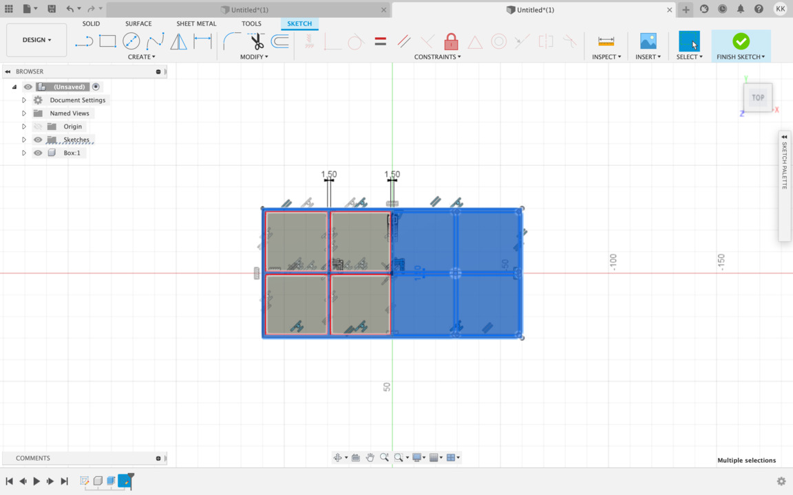
- Choose top face of component and press Create sketch. Create Central Rectangle in the middle (57x1.5mm). Then create Line, take construction and from the center of the origin draw construction line. Create one more Central Rectangle directly on construction line, uncheck construction option in the scketch pallete menu. Touch Rectangle to shortest wall and create 1.5mm x 5.8mm and hit enter. Create one more Central Rectangle - make sure that it hit walls and choose 1.5mm width. Choose Trim tool and trim all the lines that blocking us from complete sketch. Trim unwanted sketch. Now you need create mirror sketch on the other side - for that you need to draw construction line from the center 90 degrees down. Hit escape to exit line command, then select sketch what you want to mirror, choose Mirror tool from the menu. Mirror line will be construction line and now you have the same sketch on the other side. Trim again all the unwanted parts and after that click finish sketch.
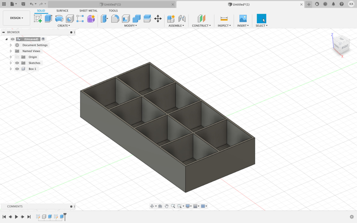
- Now you have to extrude walls 20 mm.
- Compartments are ready! Now you need to make a lid.
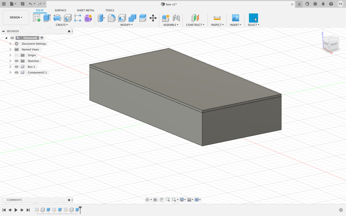
- For make a lid you need to create a sketch on top of compartments face and then simply gonna draw another rectangle. Click finish sketch. Now you need to extrude to create a lide 1.5mm high and choose Operation - New Component.
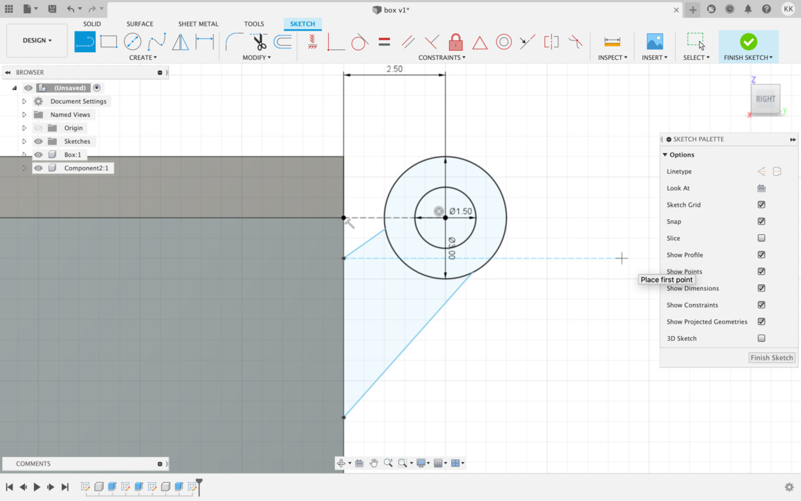
- Now you need create a hinge and the lock so that it won't open by itself. Create sketch, then create construction line 2.5 mm away from box, then uncheck construction option. Choose circle and make 1.5 mm circle. Make one more circle around - 3 mm. Choose line and draw a line from circle to box, then draw one more line and then draw a line from lid to the box. For close sketch you need to make lines tangent to the circle, so choose the line and the circle. Click finish sketch.
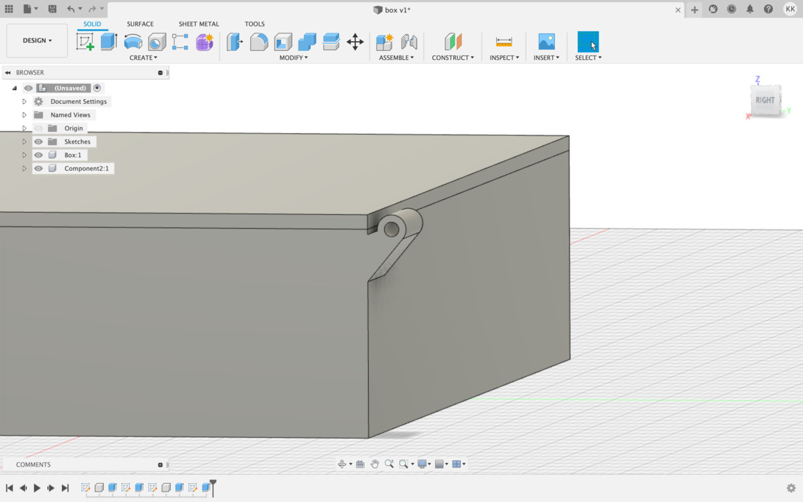
- Now, you have hinge sketch - let's extrude it (choose the circle and part what you tangent before). Extrude it in -10 mm and hit OK.
- Reactivite sketch and choose same for lead - other two parts. Hit extrude with the offset -10.3 mm. Repeat the same process one more time, but for the box component. Choose extrude, select parts what you choose first time, extrude -10 mm with offset plane -20.6 mm and click OK.
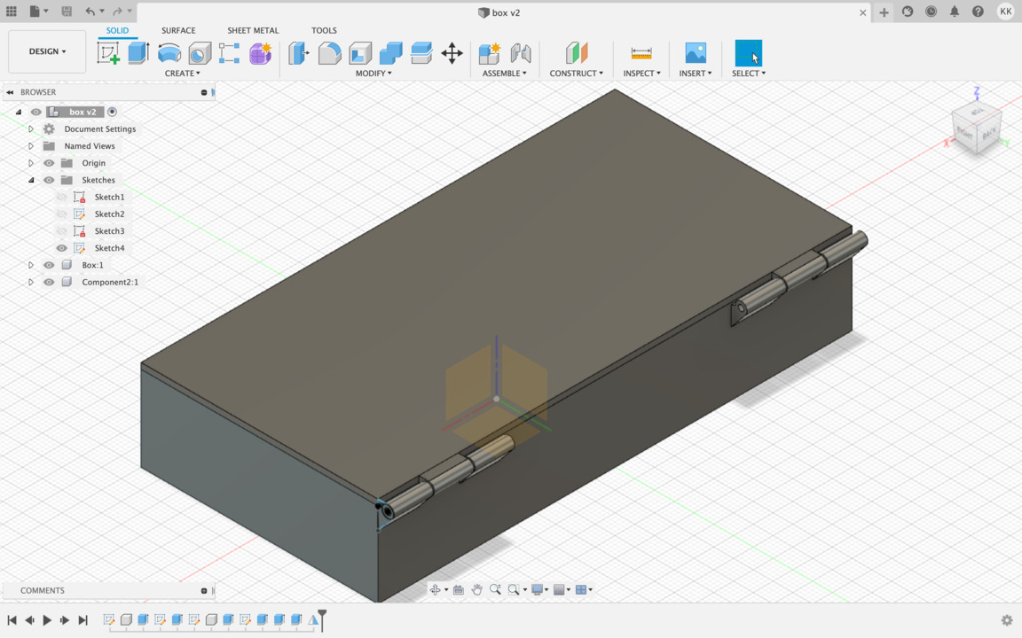
- Looks nice!
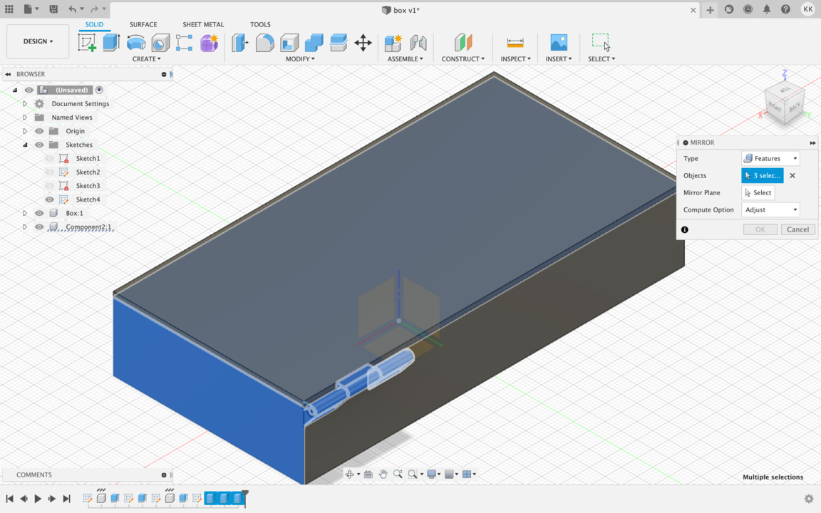
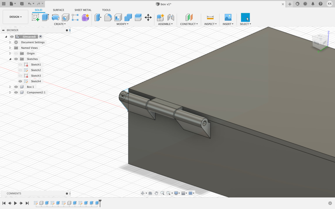
- To do that on the other side all what you have to do is choose Mirror tool from Create option, type Features and in the bottom tools panel choose last threee extruded features, then click Mirror Plane and click OK.
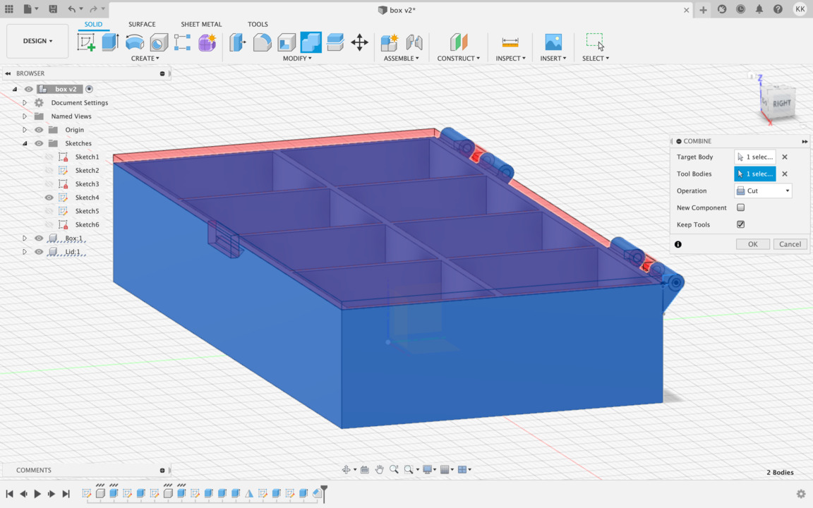
- Now let's create lock that will keep box closed. For that you will need to create sketch on front face. Choose Central Rectangle and make 5 by 12 mm long square. Draw one more line and trim unwanted (sketch) lines. Click finish sketch. Then extrude sketch 1.5 mm, select Operation - Join and make sure that box sketch is unvisible. Click OK. Rename second component name to lid. So, now you need to make lock. For that all what you have to do is create sketch on inside lock wall face. Choose 2-point rectangle and drag half of face. Finish sketch. Then extrude lock of inside wall 1 mm long. Now from Modify tools choose Chamfer and click on the lock (inside line) and make it smooth 1.2 mm. Box turn back on, choose Combine in panel Target Body will be a box, Tool Bodies will be a lid.
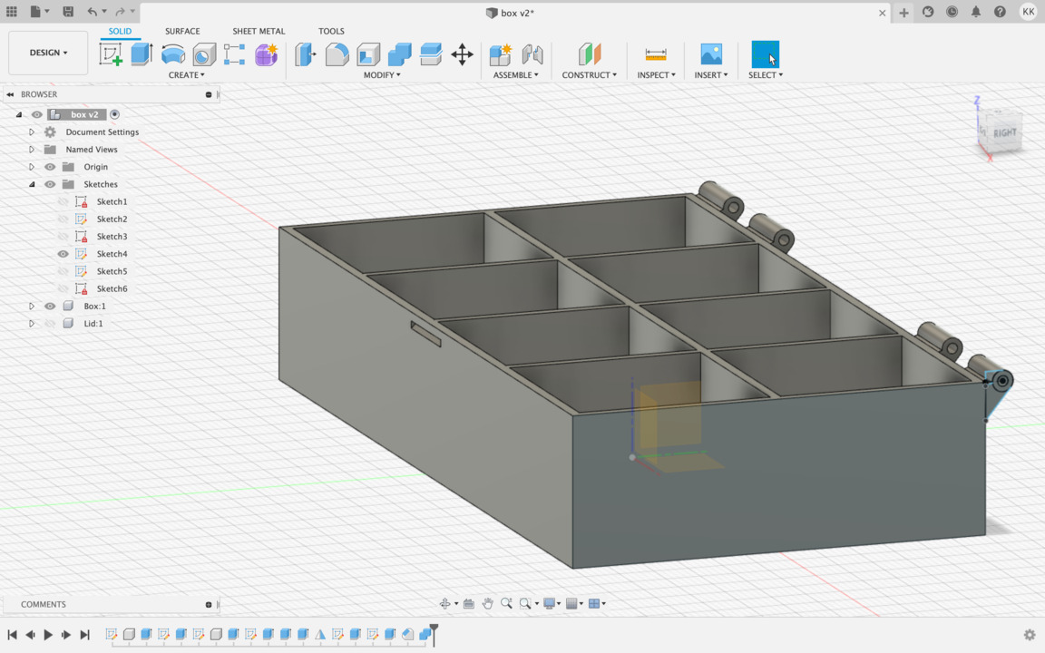
- When remove lid, you can see that you have small cut out from lid.
- Click extrude choose profile of compartments, lid turn back on and extrude it 0.2 mm, choose Operation - Cut and click OK. Now you can see cut outs in lid. Choose extrude, select all cubes and extrude them 2 mm. Then select each edge and make it more smooth. For that choose - Modify - Champer and select each edges. When everything is selected make 1.5 mm smooth Champer and click OK.
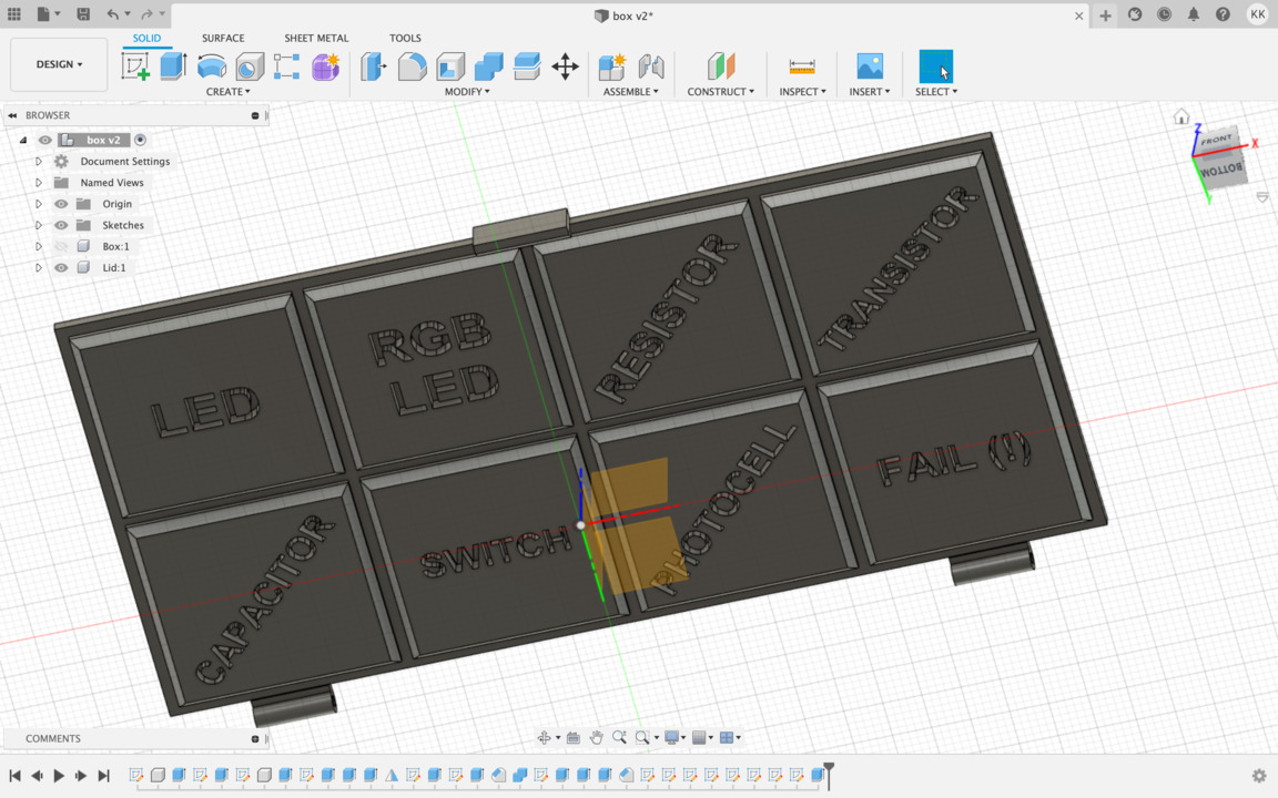
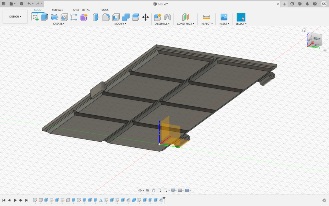
- Now you can put text on each square. Create sketch, from create option choose Text, define your text area, then type LED (in my example), choose bold, align center and alignment middle. Then finish sketch. Repeat it for all boxes. Then extrude - choose all text parts -2.5 mm
- And finally, experiment of Appereance.
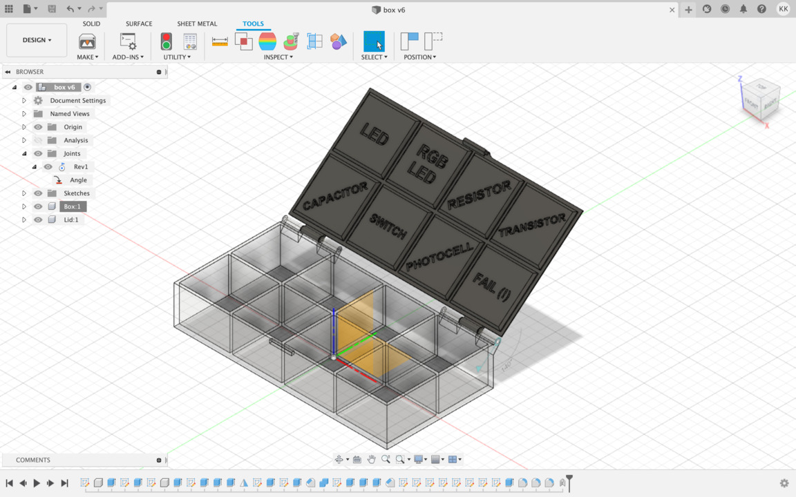
- Choose Assemble option As-built Joint, components will be lid and box (2 selected components). Joint Type choose Revolute and choose hing part (inside - circle), rotate Z-Axis. In folder Joints right click and choose Edit Joint Limits. Maximum rotatation value is 195 degrees. Click Animate. Very well!
STEP 2 : WORK WITH LAYERS
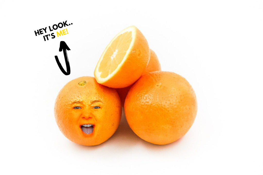
THIS IS A RESULT OF GIMP EXPERIMENTS AND IN THE SAME TIME - 'HERO SHOT' THAT I DID IT:
BEHIND THE SCENES
3D design

STEP 1 : CREATE BOX.
STEP 2 : CREATE A HINGE AND LOCK.
STEP 3 : TEXT