Week 8 - Group assignment - Embedded programming
Assignment
compare the performance and development workflows for other architectures
Boards comparison
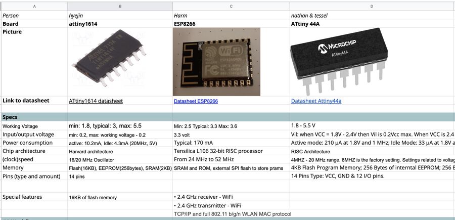
First, e made a comparison chart for three different boards, ATtiny1614, ESP8266 and ATtiny44A. Each of use read a datasheet for each board and wrote down the specs such as working chip architecture, clock speed, memory and special features.
Workflows
Workflow 1. ATtiny1614
-
Microcontroller: ATtiny1614
-
IDE: Arduino IDE
-
Program download: UPDI, pyupdi library
-
Communication: FTDI, miniterm
-
Program I used in this example: Blink an LED and print texts
-
Open Arduino IDE and download megatinycore package
-
Select your board from Tools > Board
-
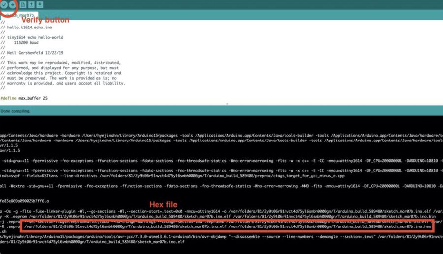
Write down the LED blink code into Arduino IDE (code link)
-
Press the Verify button. This will create a .ino.hex file. Copy the whole directory starts from the beginning. (In my case, it started with /var/folder/81…)
-
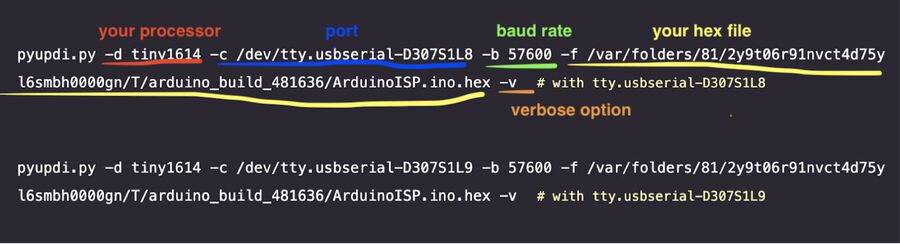
Now you have to download pyupdi (github link: https://github.com/mraardvark/pyupdi) to download your program with UPDI. Go to the terminal and type the command below.
-
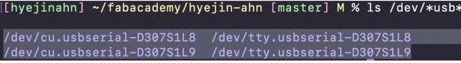
Check if the USBs are connected (for mac users, type
ls /dev/*usb*) -
On the terminal, run the codes below. It turned out the UPDI cable was connected to tty.usbserial-D307S1L8. Which means the FTDI was connected to tty.usbserial-D307S1L9.
-
After downloading the program, youc an communicate with the board through the FTDI cable
-
Then, the miniterm will be opened. You can see the response from the board here.
pip(or pip3) install https://github.com/mraardvark/pyupdi/archive/master.zip
I didn't know what’s the difference between /dev/cu and /dev/tty. So I used /dev/tty one and it worked well.
We are going to use one of these USB to program the board. It’s hard to tell which USB is the UPDI and the FTDI. I just tried both ports and saw which one worked.

Workflow 2. ATtiny44
-
Microcontroller: ATtiny44
-
Development environment: MAKE
-
Program download: MAKE and AVRdude
-
Communication: USBTiny programmer
-
Program I used in this example: Blink LED
-
Open a text editor of your choice. I used Sublime.
-
Write a program in C.
-
Save the file as .c. In this example: switch.c.
-
Open a text editor of your choice.
-
Save the file in the same directory as your .c file.
-
The MAKE file must be named Makefile. It does not have an extension.
-
Add the following to the Makefile
-
Install AVRdude and MAKE on Linux with the command: sudo apt install avrdude gcc-avr avr-libc make.
-
cd into the directory where your switch.c and Makefile are stored.
-
Run make. A .hex file and out. file should be produced.
-
Run avrdude -c usbtiny -p t44 to see if your programmer is recognized.
-
Run avrdude -p t44 -P usb -c usbtiny -U flash:w:$(PROJECT).c.hex where you replace $(PROJECT) with the name of your project.
Example code in C. LED is off. When button is pressed, LED is on.
/*
Demo of the simplest on/off button code for Tiny44.
This is adjusted code based on the example code of Robert Hart: http://fab.cba.mit.edu/classes/863.15/doc/tutorials/programming/Simple_examples/c_prog_examples.html. & with adjustments of YLi: http://fab.cba.mit.edu/classes/863.15/section.Harvard/people/YLi/Week%207%20-%20Embedded%20Programming/Ye_001.c

This code works by directly manipulating the register bits

In my case:
Switch connected to PA3 (physical pin 10 of tiny44)
Yellow LED connected to PA7 (physical pin 6 of tiny44)

For details on the use of the registers PORtx, DDRx, and PINx  (where x = A or B) see tutorials on AVR programming.

This program was written by Robert Hart as a simple demonstration of programming AVR microcontrollers.
*/

// ------- Preamble -------- //
/*This is a library that needs to be called upon for MAKE to know what to make of the code*/

#include <avr/io.h>

/* int main is a special function. It is added to all C code. All other functions are wrapped inside this function*/
int main(void) {
  // -------- Inits --------- //

/* initialize pullup resistor on our input pin (switch) by setting the bit of PA3 of register PORTA high. Check page 66 of the ATtiny datasheet for the register description.*/
  PORTA = 0b00001000;
 /* Here we declare the LED pin PA7 as output pin by setting the DDA7 bit in the DDRA register to high.  (datatsheet p.66) */
  DDRA = 0b10000000;

  // ------ Event loop ------ //
  /*while (1) declares a loop because 1 is always true.*/
  while (1) {
/* look for button press */
     if ((PINA & 0b00001000) == 0 ) {         /* test to see if bit 3 of PINA is low  */
      PORTA = 0b10001000;                   /* turn on LED on pin 7 of port A if bit is low (button is pressed) */
    }
    else {                                  /* otherwise */
      PORTA = 0b00001000;                  /* leave output low.    */
    }
   }

                                             /* End event loop */
  return (0);
 }
PROJECT=switch
SOURCES=$(PROJECT).c
MMCU=attiny44
F_CPU = 20000000


CFLAGS=-mmcu=$(MMCU) -Wall -Os -DF_CPU=$(F_CPU)

$(PROJECT).hex: $(PROJECT).out
    avr-objcopy -O ihex $(PROJECT).out $(PROJECT).c.hex;\
    avr-size --mcu=$(MMCU) --format=avr $(PROJECT).out

$(PROJECT).out: $(SOURCES)
    avr-gcc $(CFLAGS) -I./ -o $(PROJECT).out $(SOURCES)


program-usbtiny: $(PROJECT).hex
    avrdude -p t44 -P usb -c usbtiny -U flash:w:$(PROJECT).c.hex

program-usbtiny-fuses: $(PROJECT).hex
    avrdude -p t44 -P usb -c usbtiny -U lfuse:w:0x5E:m
(1) PROJECT=switch. The project name *must* be the same name as the filename of your .c file. In this case switch
(2) Leave line 2 as is.
(3) MMCU here you name your microcontroller.
(4) F_CPU is the frequency of the board you program.
(5) CFlags are compiler flags. You can leave as is.
(6) The $(Project) functions tell MAKE what to do. Leave as is.
(7) The next two functions are AVRdude commands to flash the code and program the fuses respectively. In theory running the MAKE file in your terminal will execute these AVRdude commands automatically. That did not work for me but you can manually enter and execute these commands in the terminal.
The program should now be installed on your microcontroller.
Workflow 3. ESP8266
Download and install Arduino IDE
Download and install the driver CP210x USB to UART Bridge VCP Drivers
Add the Esp8266, File > Preferences. At “Additional Boards Manager URLs” paste http://arduino.esp8266.com/stable/package_esp8266com_index.json Click OK
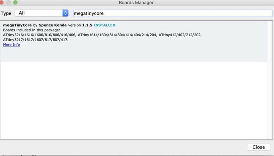
Under tools > Boards > Board manager. Search for "ESP"
Install ESP8266
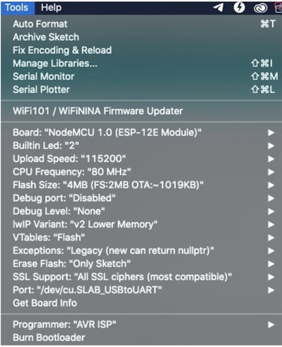
Plug in the board in your USB and use these settings:
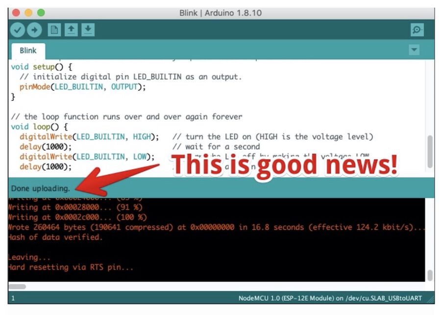
Go to File > Examples > 01. Basics > Blink
Upload the code (press arrow/ CMD-U on Mac)
If all goes well, you will see ‘Done uploading’ in the Arduino IDE and the LED on the board will blink.