Week 12 - Interface and application programming
Assignment
Compare as many tool options as possible
Harm: Scratch for Arduino (S4A), ArduBlock, Minibloq, mBlocks
Tessel: Processing
Hyejin: Node-RED
Nathan: PySerial, TKinter
1. Block-based visual programming language
What is a "block-based visual programming language?
Block based coding is a way of programming code in a visual way where as text based coding uses text.The problem with text based coding is the syntax, you need to be exact. One comma will completely disable the code to be interpreted by the computer. My students are complaining about this a lot, this does not feel human.
How can you use it to interface with a Microcontroller board?
I found 3 ways
S4A: is a Scratch modification http://s4a.cat/
Ardublock: http://blog.ardublock.com/
Minibloq: Standalone program, no Arduino needed. http://minibloq.org/
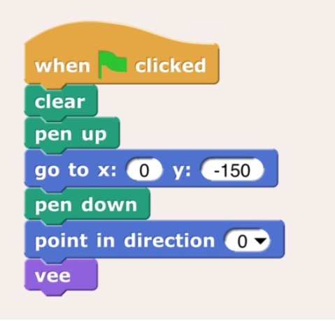
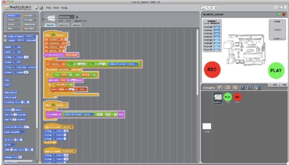
Scratch for Arduino (S4A)
Based on the Block based coding program 'Scratch' from MIT. Is an add-on to Arduino. It works on Mac, Windows and several Linux distributions. I will install and test this add-on.
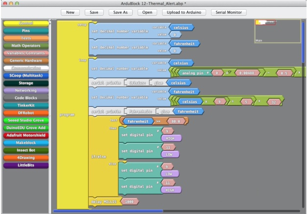
ArduBlock
Is an "add-on" to Arduino, it works for Mac, Linux and Windows
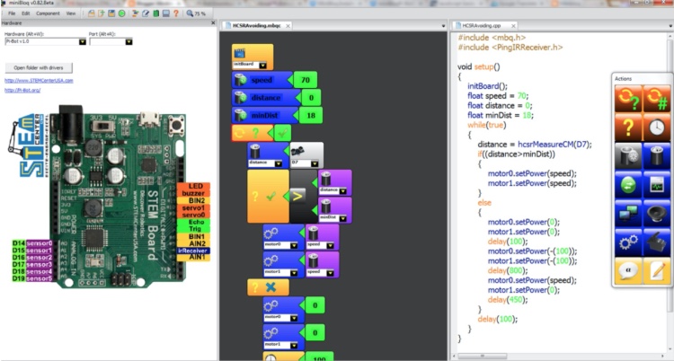
Minibloq
This is such an ugly interface, I'm not tempted to test it. It is only available for windows. So I don't have to. The nice thing about Minibloq is: it realtime translates the blocks into code, so it will help you learn code.
Installing Scratch 4 Arduino on the mac
I followed the instructions from http://s4a.cat/ (download & install). After downloading I opened the S4A16.dmg Disk Image file. The dialog below appeared and I dragged S4A in Applications.
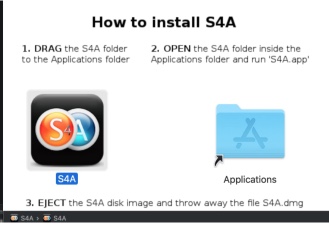
I looked in the Applications folder the S4A.app. It showed up but couldn't be opened because the App does not work with Catalina (my version of macOS)
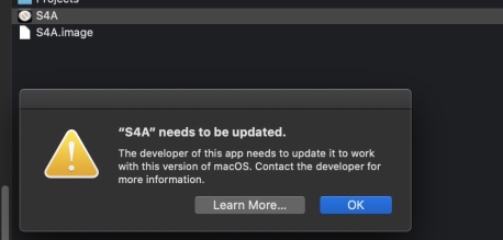
pI found solutions via https://groups.google.com/forum/#!msg/s4a-community/0wJLBsK-KME/bTvD1zqOBAAJ
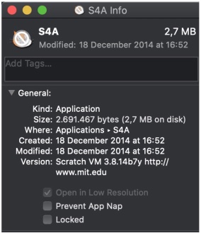
Some people using Catalina report this works: sudo xattr -rc /Applications/S4A/ I executed this, no error messages. But still I couldn't open S4A. I looked at the Application file. It was updated in 2014, their last blog post was on 2016 and I can't find any lead on how to fix this (via google search). So I give up!
Install ArduBlock
Go to the install section: http://blog.ardublock.com/engetting-started-ardublockzhardublock/
Download
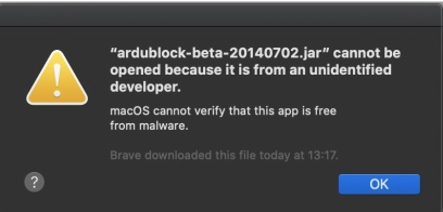
Open the .jar file.
You will get a warning, I clicked OK
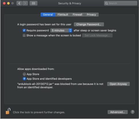
Open System Preferences > Security & Privacy I clicked Open Anyway
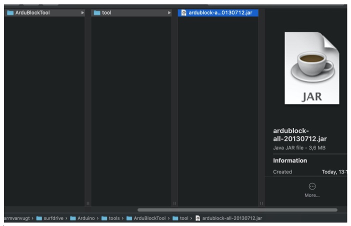
Now place the .jar file in a 'tool' folder under your Arduino documents (find this via your arduino preferences). You have to create these folders yourself.
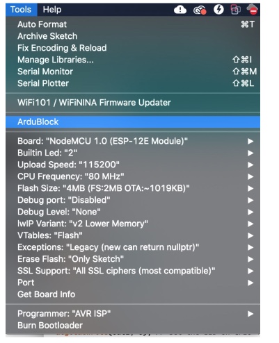
Now restart Arduino, and go to 'Tools', if all worked well you should see ArduBlock:
After opening ArduBlock I followed this tutorial on youtube and created my first 'program'. But when uploading this to the arduino sketch I got a warning.
Arduino Version: unknown
        Exception in thread "AWT-EventQueue-0" java.lang.NoSuchMethodError: processing.app.Editor.setText(Ljava/lang/String;)V
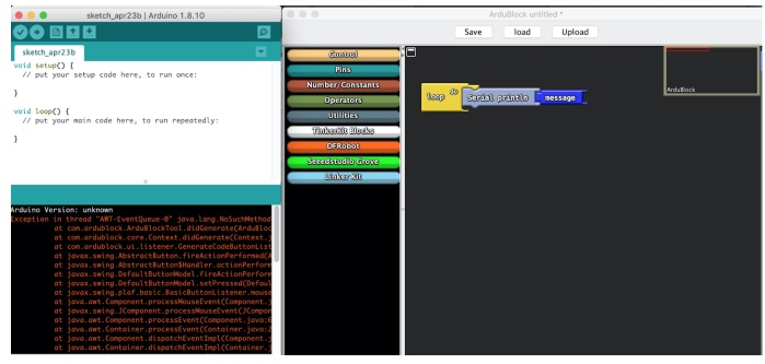
Looking for a solution, I found almost nothing. But the most recent posts about Ardublock are from 2017. So Again, I spend a lot of time installing and discovering outdated software.. Feels stupid, but It would be better if software ALWAYS comes with a date!
mBlocks
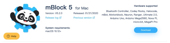
Using Google as a starting point i found another way to program using Visual blocks: mBlocks. mBlocks is a version of MIT's Scratch especially made for Arduino boards. They clearly show their versions, last one for mac was Released: 01/21/2020. https://www.mblock.cc/en-us/download
So they don't support NodeMCU.. I gave it a try anyway.
Downloaded and installed mBlock 5
Opened mBlock. Again I had to approve it via the Security & Privacy settings of mac
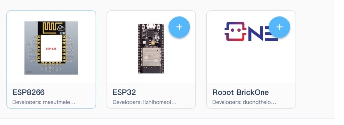
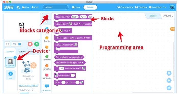
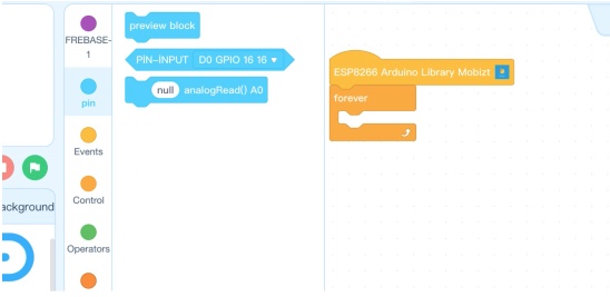
First thing I tried is to Add an ESP/NodeMCU. To my surprise I found the ESP8266 (ESP-12) in the menu.
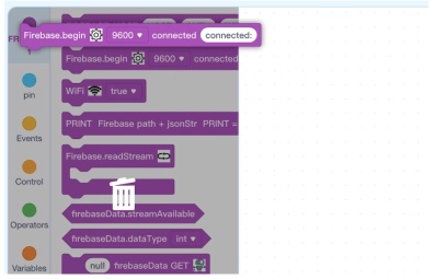
After adding this the UI showed a different set of Blocks:
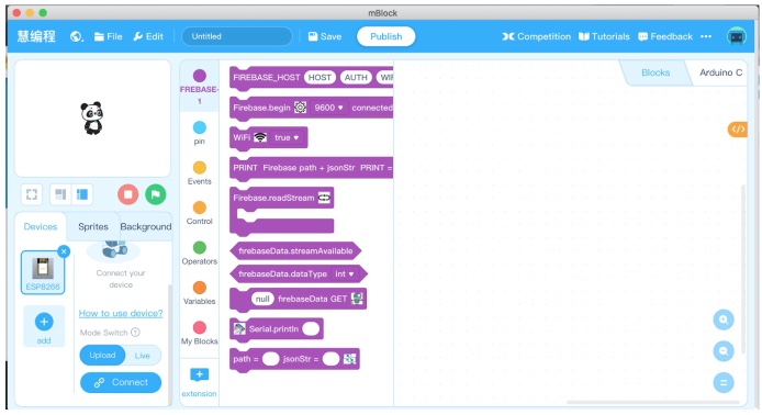
I don't recognize the "firebase. But 9600 looks like the bout rate for communication. A google search shows me: firebase is a Google Webapp hosting service from google. https://firebase.google.com/ This code could probably connect to my Wifi and send something to firebase. I don't have an Firebase account and want to start simple. So I decided to delete the code blocks.
Delete = Drag a block to the left, you will see the Bin popping up.
But this is not working?! I took a closer look, and it turned out 'Firebase' is just one of the clusters of blocks... It is not the program!
But before I dive to RTFM how to program with mBlock, I will make sure I can use mBlock to program a NodeMCU/ESP12-F
Connect to the NodeMCU v2
I closed Arduino
Connected an NodeMCU v2 via USB (make sure you install the driver for the CH340 UART chip)
Added the ESP8266 (in mBlock via tab Devices)
Click 'Connect' (in tap devices, scroll down to find the button)
It did not show any devices:
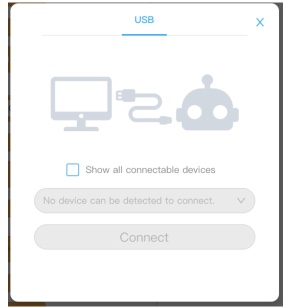
But after checking the check mark "Show all connectable devices". It did see my board (Just like in Arduino this NodeMCU is called usbserial-1410):
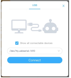
And clicked 'Connect' It showed it was connected!
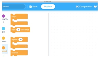
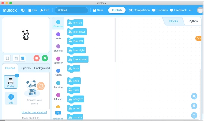
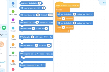
I want to make my Blink code. But I cannot find any block for outputs. The example below is made in 10 seconds. And it feels and looks (sound is nice too!) really charming. But without any output blocks it is useless...
I followed this manual, showing me how to make Blink. But in this example output blocks are available. Only for some Arduino UNO and other original Arduino boards! When choosing the arduino Uno the output pin is available, and I made the blink code in 10 seconds:
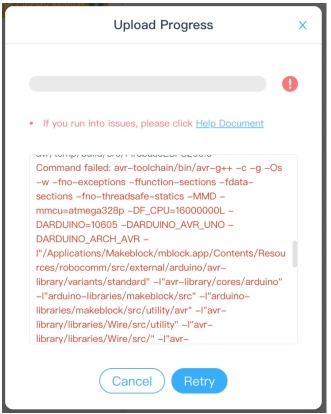
But I can’t upload this to the ESP module, it is UNO compiled code. I found a manual on the internet, only in chinese… https://www.youtube.com/watch?v=HZ07qr7TbWk. I tried to upload an empty sketch to the nodeMCU. Uploading works, but it came back with an big error message:
My conclusion: mBlock is really cool. The restriction is not the biggest problem, but trying to get it to work with non standard hardware is very hard. This is caused by a complete lack of (non chinese) help from the community. I spend hours searching for posts, manuals I’m so used to find when using the Arduino platform.
When it comes to programming, it is not so restricted, but I you have some experience in programming it can be frustrating.
I tried to make a simple program using the Arduino Uno settings (without being able to test this, since I have no access to an UNO). I do generate readable code. You can see the code while you are dragging blocks.
This code will count every 0.1 sec up (i) from 5 to 50, display (i) every count. If i is 50, it will print Fifty!!! In the serial monitor.
Than it will count back (every 0.1 seconds) till it reaches 0 and will print ZERO
In the serial monitor.
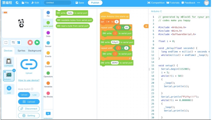
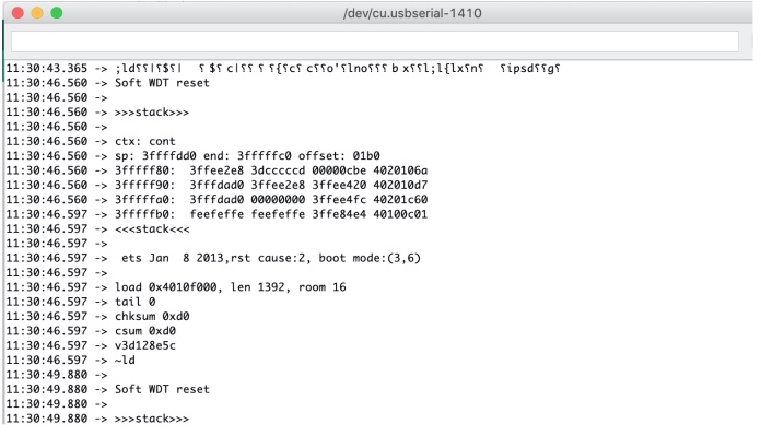
Since I don’t have an UNO. I pasted this code to Arduino IDE and run this on a NodeMCU. It only showed strange characters in the serial output:
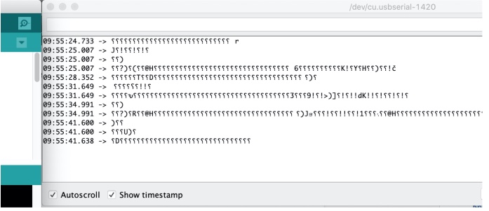
I found the code uses a serial communication speed of 115200 (is this standard for UNO?) in the line Serial.begin(115200);
I changed this to 9600 and there is a visible output. But a ‘reset code’
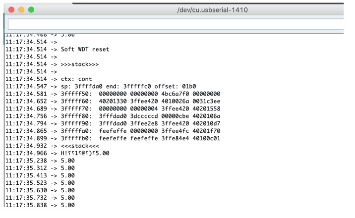
https://forum.arduino.cc/index.php?topic=442570.0 tells me this is: "The ESP8266 is a little different than the standard Arduino boards in that it has the watchdog(WDT) turned on by default. If the watchdog timer isn't periodically reset then it will automatically reset your ESP8266." Looking at the code. It is not what I expected, It is missing the incrementing of the ‘i’ but I don’t see a reason to Reset the ESP8266 I remade the code in mBlocks. It is really fast and it is fun to do, clicking blocks together and making duplicates, draggin around. Really easy.
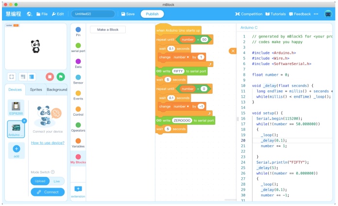
I duplicated the code to the Arduino IDE, uploaded to a NodeMCU. Now it resets all the time:
I made a code using the ESP-12e settings.
#include <ESP8266WiFi.h>
#include <Arduino.h>
#include <Wire.h>
#include <SoftwareSerial.h>

float number = 0;

String al;

void _delay(float seconds) {
  long endTime = millis() + seconds * 1000;
  while(millis() < endTime) _loop();
}

void setup() {
   int sensorValue = analogRead(A0);
  number= sensorValue * (5.0 / 1023.0);
  _delay(1);
  Serial.println(number);

}

void _loop() {
}

void loop() {
  _loop();
}
It should read from the A0 on the NodeMCU. This code really looks strange to me:
The nothing is constantly running: The loop is calling _loop(). This function is not doing anything.
The reading of the sensorvalue should not be in the setup()
It shows the analog sensorvalue as a 5V value. But I set the board to NodeMCU with is 3.3.V
>Serial.begin is missing in het setup
I changed the code to this (yellow is changed):
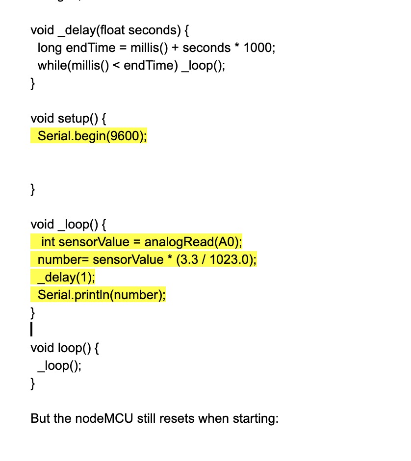
But the nodeMCU still resets when starting:
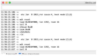
This could be caused by the fact _loop() is being called by _delay AND by loop(). I disabled _loop from the delay
         void loop() {
         //  _loop();
      }
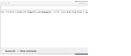
The output was: So no crash, but just no output (it is normal a NodeMCU produces one line of serial monitor gibBerish)
Conclusion My time is up (times 2!): so my final conclusion. There is no support for nodeMCU, It just generates buggy code. Only when they fully support it I will try it again. But I can recommend mBlocks to anyone who would like to play around (not only kids) with an Arduino UNO and create some fun projects.
2. Processing
Processing is both a development environment and a language for learning how to code. It focuses especially on visual arts. Processing looks very much like the Arduino IDE. Or rather, Arduino looks like Processing. It was modelled after it. This is what the workbench looks like:

To start up Processing, download it, cd into Processing directory "/Downloads/processing-3.5.4/"and run "./processing". There a good tutorial to get you started. If there is something in the code you want to learn more about you can right click on it. A web page will open that explains the reference. Under "Help > reference" you can find the entire reference book. You can make a static sketch this performs a task or creates an image without animation of interaction.
You can also make an interactive program: a series of frames by adding "setup()" and "draw()". These are build in functions that are called automatically. At its foundation, Processing works with a "setup()" and a "draw()" block. As with Arduino IDE setup is used for initialization. "Draw" is equal to Arduino IDE "loop" and runs repeatedly. As with Arduino there are many libraries that you can import into Processing and can make use of.
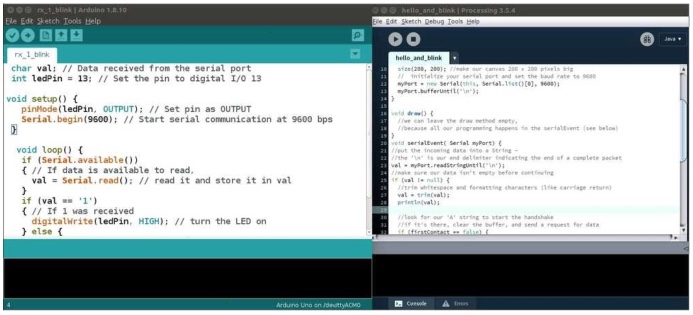
Arduino IDE next to the Processing Development Environment.
Once you’ve made something you can simply export it as a stand-alone application by selecting: "File > Export Application". Java Runtime is included in the app directory which means it can be run independently of what is already installed on the computer of the user. The drawback is that the file becomes very big. A simple application can come at a cost of 250MB.
With Processing you can make applications that communicate with devices. Processing works well together with the Arduino IDE. You can write code to program your device in Arduino and write code to make an interface in Processing. By making use of libraries you can connect the Arduino code to the Processing code. I used serial communication to have the interface interact with the device. Perhaps there are other methods as well but I do not know about those.
Here is an example. The goal is to turn an SSD1306 OLED monitor on and off. I started out with example code that is part of the Tiny4kOLED library that is used in Arduino to run an OLED monitor. The example displays a bitmap on the monitor. I added the code from "Serial.begin" onwards. This makes the device listen on the serial port. Then when it receives an "r" it should turn the monitor on, if it receives a "y" it should turn the monitor off.
/*
 * Tiny4kOLED - Drivers for SSD1306 controlled dot matrix OLED/PLED 128x32 displays
 *
 * Based on ssd1306xled, re-written and extended by Stephen Denne
 * from 2017-04-25 at https://github.com/datacute/Tiny4kOLED
 *
 */


// To use the Wire library:
#include <Wire.h>
#include <Tiny4kOLED.h>
#include "SolomonSystech.h"

// ============================================================================

void setup() {
  // put your setup code here, to run once:

  oled.begin();

  // Two rotations are supported,
  // The begin() method sets the rotation to 1.
  //oled.setRotation(0);

  oled.clear();

  oled.on();  // turn display on
  oled.off(); // turn display off

  oled.bitmap(6, 0, 6 + 37, 4, solomon_systech_logo_bitmap);
  oled.bitmap(54, 0, 54 + 69, 4, solomon_systech_text_bitmap);

  // Now that the display is all setup, turn on the display
  oled.on();

Serial.begin(9600);   // start serial communication 09600bps

}

void loop() {
  // This example only shows a static image on the display.
  // The microcontroller could be turned off now.

  if(Serial.available()){  //id data is available to read

   char val = Serial.read();

   if(val == 'r'){   // if r received
   oled.on(); // turn screen on
      }
   if(val == 'y'){   // if y received
   oled.off(); // turn screen off
      }

   }
}
Here is the Processing code: first you call up the controlP5 library. With that you can create objects that serve as an interface like the picture below. You do that by defining squares and other forms, giving them color, a place on the X-Y axes etc.
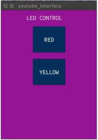
You define the objects, for instance as button. And then you can assign a function to the button. For instance, if you click the button with the mouse, send out ‘r’ over the serial port. And that ‘r’ is then received by the device. And in the ICU code we defined that if ‘r’ is received the monitor shuts off. And that is the way that Arduino and Processing work together.
import controlP5.*; //import control library
import processing.serial.*; // import serial library

Serial port;

ControlP5 cp5; //create controlP5 object
PFont font;

void setup(){

  size(300, 400); //window size

  printArray(Serial.list());  // prints all available serial ports

  port = new Serial(this, "/dev/ttyUSB0", 9600); // The port Arduino is connected to

  cp5 = new ControlP5(this);
  font = createFont("Ubuntu Mono", 20);
  cp5.addButton("on")      // add button to window
   .setPosition(100, 50) // x and y coordinates upper left
   .setSize(100, 80) // width, height
   .setFont(font)
  ;

  cp5 = new ControlP5(this);
  cp5.addButton("off")        // add button to window
   .setPosition(100, 150) // x and y coordinates upper left
   .setSize(100, 80) // width, height
   .setFont(font)    // set font
  ;
}

void draw() { //same as loop in Arduino
   background(150, 0 ,150);  //background color

   //title for window
   text("Screen on / off", 80, 30); //text + coordinate
   textFont(font);

}

// Adding functions to button. Each button sends a particular (char) character
//over the serial port.

void on(){  // the first button is named on
   port.write('r'); // In the Arduino sketch we wrote 'if(val == 'r')'
}

void off(){
  port.write('y');
}
3. Node-RED
Install Node-RED
Node-RED is a powerful open source tool for building Internet of Things (IoT) applications with the goal of simplifying the programming component. It uses visual programming that allows you to connect code blocks, known as nodes, together to perform a task.
To run Node-RED on your computer, you first have to install it. Since my computer is mac, I will explain how to install it on mac. You first have to install homebrew by typing the command below on the terminal.
Once Homebrew is installed, type brew install npm into the terminal and hit enter. This will install the Node Package Manager that we will use for downloading the next components.
Type:
sudo npm install -g --unsafe-perm node-redinto the terminal, this will install Node-Red.Type:
node-red to startNode-RED in your terminal.
/usr/bin/ruby -e "$(curl -fsSL https://raw.githubusercontent.com/Homebrew/install/master/install)"
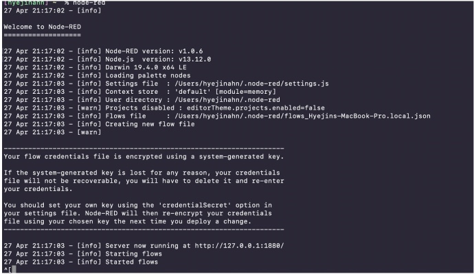
Now the server is running at http://127.0.0.1:1880/. You will see the Node-RED editor there.
Install Node-RED dashboard
Node-RED Dashboard is a module that provides a set of nodes in Node-RED to quickly create a live data dashboard. I had so much fun using it. I liked that I could make a nice looking UI by dragging and connecting some nodes. Let's install it first and see how it works. You can install it through commands (like this), but I used the Node-RED UI to install it.
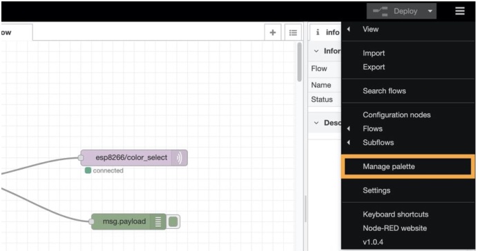
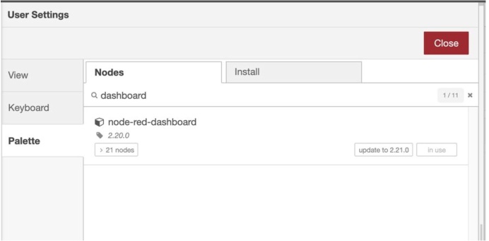
Click the Manage palette button and search dashboard, and install the package called node-red-dashboard. I found this way easier than using the terminal commands. Once you install it, now you can create a UI.
Play with the Node-RED
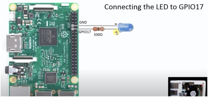
You can do a lot of things with Node-RED, but this is especially useful for home automation. Usually, people install Node-RED on Raspberry pi and control or communicate with Pi. For example, after installing Node-RED on a Raspberry Pi, you can control the GPIO pin to turn an LED on.
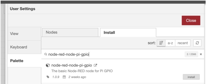
To do this, you have to install a library called node-red-node-pi-gpio like before.
And then, you can simply drag and drop the nodes from the left side bar.
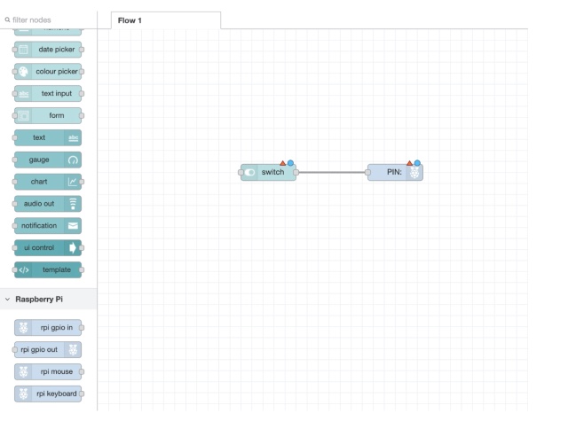
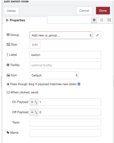
If you want to edit a node, double click it. Click the GPIO node and select the GPIO17 pin as the LED is connected to this pin. Then, click the switch node and change the payload type to number and set on payload to 1 and off payload to 0. Also you need to specify the group for the node. Once you are done editing nodes, hit the deploy button on the top right. When the deployment is done, go to http://127.0.0.1:1880/ui to see the UI version of the flow.
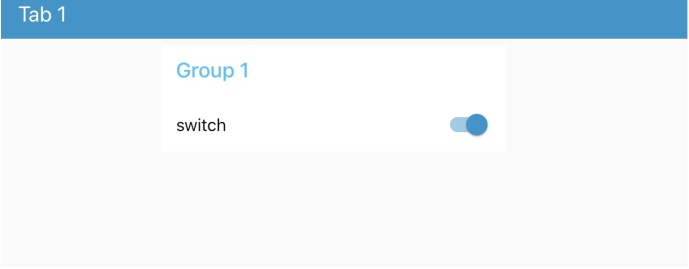
Now the UI for the flow is created. You can customize the color or the look on the editor as well. It’s very customizable and easy to change.
4. PySerial & TKinter
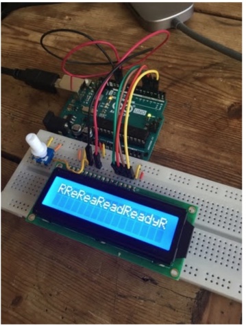
I worked on using Python scripts to interface with microcontrollers. I primarily worked with pySerial and Tkinter. I worked with an arduino connected to an LCD screen, and sent the Arduino strings via serial communication. PySerial allows you to establish serial communication with the board via the port it uses to connect to the computer. If pySerial is not already downloaded you can install it by entering the following into the command line:
pip3 install pyserialThen, it can be imported into a python application by adding
import serialto the top of the .py file. Serial communcation with a port can then be established by writing
s=serial.Serial('/dev/cu.usbmodem####', 9600)
In which the first parameter names the port, and the second establishes the baud rate. After initializing serial communication with the board, I programmed an interface which sends strings to the Arduino. The primary command that I used was
s.write(str.encode('Ready...'))
s being my variable that represents the serial port of the arduino, s.write sends the port a string, which I encode into 1s and 0s using str.encode. To test this out, I first had the python script ask for user input in IDLE
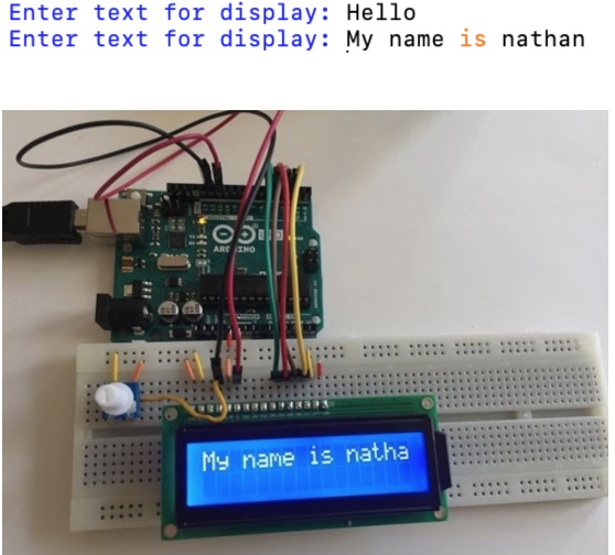
Because this worked, I moved on to TKinter so that I could take that input through a software interface.
TKinter
TKinter is an easy to use interface programming package for python, which comes preinstalled with python.
I got the hang of it by looking for a TKinter tutorial. I went with this one.
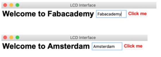
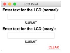
I was able to create a box with a few widgets quickly. Here was my first practice, which changed the text after Welcome to: to whatever I added in the text box.
I ran into issues when I tried to work with additional widgets imported from tkinter.tkk, so I decided to just work with the standard Tkinter Widgets. This was the final interface I created, which would take text in the first entry to print normally, and in the second entry to print scrolling and on both lines of the display at once.
The code for TKinter looks like this. At first I establish a window, then can create widgets within that window by listing it as a parameter.
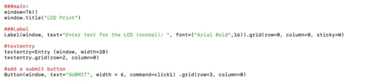
See in the button where I name a command for it? command=click1 Those commands can be written as functions within the same script.
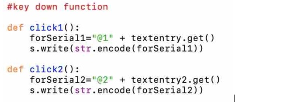
These are the commands I wrote for each button. I had the code add @1 or @2 to the beginning of each string, so that text from the different entry boxes could be interpreted differently.
Interpreting Serial Communication in Arduino
In the Arduino code, begin Serial communcation at the same baud rate as listed in the python program by entering
Serial.begin (9600);
In the setup of the Arduino code. For my program, I was interpreting strings being sent from the python program to the arduino so that they could be printed on an LCD screen. I had the LCD connected as the pins are described in the Liquid Crystal example sketch in arduino. All the flexibility comes into the program from how the Serial input is interpreted!
It is important to understand how the methods for collecting Serial information in Arduino work. At first, I tried to use the following:
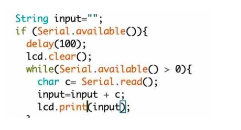
I had thought it would save each character in the string one at a time. Instead, I ended up using the following:
String input="";
  if (Serial.available()){
    input=Serial.readString();
I added additional code, to interpret the beginning of each string to catch those address markers that I added, then print it accordingly, after also removing the address. My full code is here:
void loop() {

  //addresses
  String line1="@1";
  String line2="@2";
  String clearLCD="@C";


  //Collect serial information in a string
  String input="";
  if (Serial.available()){
    input=Serial.readString();
    delay(100);


    //if string begins with 1@ print on line 1
    if (input.startsWith(line1)){
      lcd.clear();
      input.remove(0, 2);
      lcd.print(input);
    }


    //if string begins with 2@ print on line one and two and scroll
     if (input.startsWith(line2)){
      lcd.clear();
      input.remove(0, 2);
      lcd.print(input);
      lcd.setCursor(0, 1);
      lcd.print(input);
Comparison between the different platforms
We decided we all would tell each other how our platforms work and then we could compare them on such features as usability and ease of use.
Hyejin: NodeRed
Harm: S4A (Scratch 4 Arduino), Ardublock and Minibloq.
Nathan: PySerial
Tessel: Processing
It is very much like Arduino. You need a bit of time to figure out what commands to use. But once you find out where to look for them it is a lot of fun to use.
Comparing
Learning:
Much documentation online?
Support:
mBlocks support is oke, but not very big when it comes to arduino
Easy
mBlock: simple things are easy, you can’t make mistakes in syntax. But harder when making complex code.
Learning curve:
mBlocks, easy from the beginning, very hard if you want something ‘not standard’
Previous knowledge required
Graphic user interface (UI):
Which language:
Advise: use it or not