Electronics design
Week 6- Documentation
Assignments:
- Group assignment: Test runout, alignment, speeds, feeds, and toolpaths for your machine
- Individual assignment: Make (design+mill+assemble) something big
Gunnar the chair:
Gunnar the cair was a chair that I made in a Fab lab class in my upper secondary school in 2018. I named the chair Gunnar and the inspiration behind the name is Ikea and all the Ikea furniture has names and Gunnar was the first name that came to mind. The chair took a lot of time to desing and where there 5 prototypes that I made in 3D before I settled on a desing (only one prototype was cut out to make a small model of the chair). The final design of Gunnar is very stable and 
surpricingly comfortable and does the chair fit amazingly well together and needs no screews. I was the expexting the chair to fall apart easally and I had made holes for screews to make the chair not fall apart but there where no need for those holes because the chair fits so well together. I made a small prototype of Gunnar and because of the kerf the prototype falls apart easally. After I made the prototype I made two chainges to the design: I made holes for screews and I also made the back lebs a bit wider at the bottom to make it more stable. I designed the chair in Sketchup make and used the Face SVG exporter plugin to make and export the file as SVG.
Hannes the shoe closet:
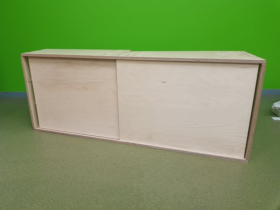
Like my chair Gunnar, my shoe closet also got a name like Ikea furniture: Hannes. Hannes is a small shoe closet that is made to fit perfectly into my fourier at home. Hannes is simple and elegant and made to fit into the enviroment at home. Hannes has designed to fit around the space heater and also gets wider where to heater is use the space better. I started out by measuring my fourier at home because I wanted Hannes to fit perfectly into my fourier. I did not have a lot of space to work with and there was also a space heater that I neded to make Hannes fit around and the side that has the heater is also wider to make more space. 
I started out by making a rough sketch of the space that I was working with and then called my mom and asked her for dimensions and after my mom had measured the fourier I imported the dimensions into my sketch. After that I started desinging in Fusion 360. After nearly finsishing the desing I was not able to edid one pice and I got really frusterated and thought to myself if it where possible to make it faster in Sketchup. I tried designing it in Sketchup and what had taken me all day designing in Fusion I did in 25 minutes in Sketchup with no problems. After desingning it in Sketchup I saved it as an SVG ant then opened it up in VCarve pro.

Hannes the shoe closet: VCarve
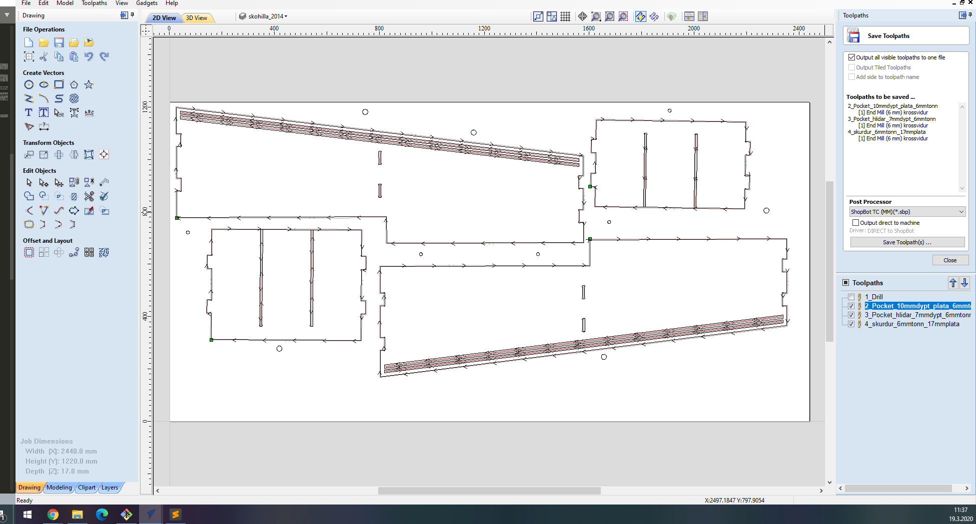
- After you have opened the file in VCarve pro you start by settnig the mesurements of the material that you are working with. In my case it was 1220mm by 2440mm and I was working with both 9mm and 17mm plywood.
- Then you start editing the file by making dogbone with the fillet tool and selecting the dog bone, the drill bit that I was working with was 6mm so I used 3.1mm dogbone. You set the dogbone where the pressfit joints are so that the pices fit well together.
- After you have edited the file you make the parts that are supposed to be cut together fit into the material.
- When you are happy with the placements of your piceses you start to make the paths for the pockets and the cuts.
- To make the pockets you select where you want to have the pockets and then select the pocket tool in the right top corner. When you have selected the tool you will get a lot of optiones of how deep the pocket will be and what tool you are using and so on. When you have selected all of that you click "calculate" and then you can see how it will be cut and if you are happy you name the path.
- To make the cuts you select where you want to cut and then you select the profile toolpath tool and after clicking that you will get a lot of ortiones and you want to cut through the material and I like to make the cut 1mm deeper than the material. The other settning that you want to make sure to have on are the taps and I usually always keep the defult settings and how many paths it will cut before it cuts through and I used 3 for the 9mm material and 4 for the 17mm material. you also want to make sure that you have the right tool selected. When you have selected all you click "calculate" and if you are happy you name the toolpath.
- After making all the toolpaths you save the toolpaths and if you don't need to change bits or if you are not making holes for screews to hold the material you can save all the paths together. To save the toolpaths you click save toolpath and select "ShopBot TC (MM)*skp)" and check if you are saving all the toolpaths in the "toolpaths to be saved" and if you are happy you save them.
- Because I was working with 9mm and 17mm materials I needed to repeat the process with the other material.


Making the shoe closet: CNC
- I started out by putting the material into the CNC and if you are not going to make the CNC mark where to set the screews you screew the material in this step.
- I started out by moving the fies into the computer and then turned of the virus protection and the internet beacause those thing can disrupt the CNC.
- Then I turned on the machine by turning the big switch
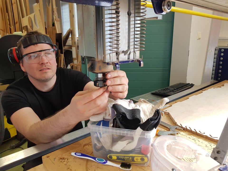
- Then I changed the bit by unscreewing the collet and taking it out and when I had removed the collet I changed the bit. Make sure that you have the right collet for the bit. Then I inserted the bit into the collet and then the collet into the machine and then screewed the lit back on(not too tight).

- Then I pressed the display button five times and then the arrow up button once and then the screen said lo and then I pressed the run button and then the machine started spinning.
- Then I opened up the shopbot software on the computer and pressed "k" to activate the keybord for moving the machine around. You use the arrows to move it around and page up and down to move it up and down.
- Then you move the X and Y to the place you want to have the 0 axis and then you select "zero axis" and there you select the X and Y and press ok and then you have 0 the X and Y.
- To Zero the Z it's good to move it somewhere where there is a lot of space to place the metal plate that is on the machine. Then you close the keyboard tab and then click the zero Z button in the bottom right corner and then the software asks you if you are ready and then you place the metal plate under the bit(great to have a friend to help you with this) and press ok, then machine lowers the bit until it touches the metal 2 and after that you have 0 the Z.
- After you have 0 all the axis you click the cut part button and select the file that you want it to cut. Now the CNC will ask you if your spindel is spinning and he should be and if he is then click "ok" to all and the CNC will start to cut the piece.
- When it has finished cutting klick "k" on the keyboard and move the machine to the side so you can remove the material safely.
- Now it's time to remove the material, sand it and the assemble it. It might be a bit hard to fit together but then it's good to sand the joints a bit better.

Problems:
The problem I had with this process was that I hit a wall with Fusion, I was not able to edit one of the final parts of the desing and I got frusterated and made what had taken me all day with Fusion in 25 minutes with Sketchp. Another problem that I had was that the joinery was super tight so it took blood, sweat and tears (maybe not tears) and a couple of hours assembling it. This problem in my opinion is a good problem because I hate it when there is an extra gap or it does not fit perfectly but it was maybe a little to tight with the closet. 
Group assignment:
The group assignment for this week was to test the CNC machine. We tested the machine by making a 300mm chircle and in the chircle we had tvo squares that where 100x100mm and had a 50mm long joint that was 9mm wide(the material thickness). In the chircle we also had a pocket the because the closet that I am making has sliding doors so we wanted to test that.
After we had cut the pieces we realized that the CNC was not 100% accurate. The squares where 99x100mm and the joints where 9.3mm so the CNC is not completely accurate.

Files:
Software I used:
- Sketchup: 3D design software.
- Fusion 360: Integrated CAD, CAM, and CAE software.
- VCarve pro:
- Face SVG exporter: