file: prueba_45.zip (kicad project for the testing board)
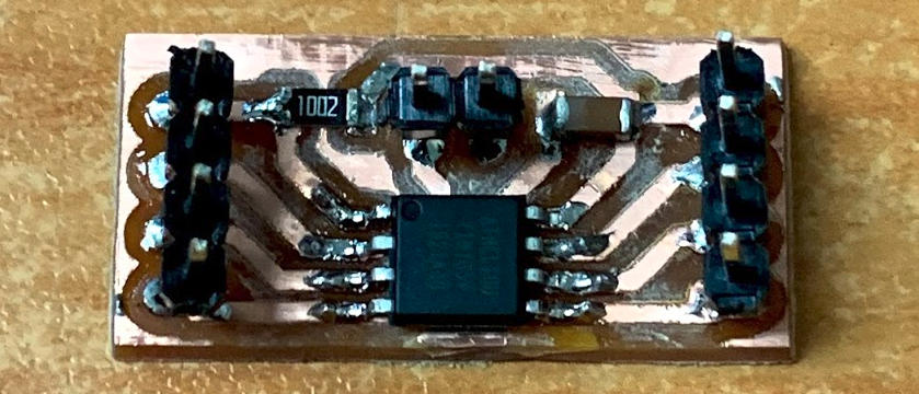
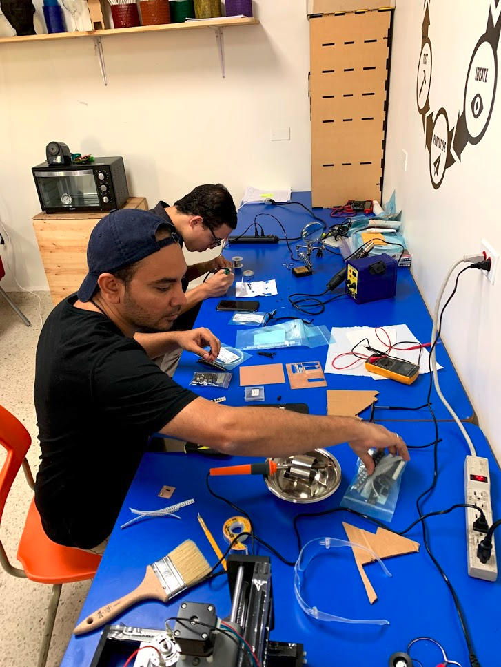
We designed a small and simple attiny45 board for testing in the lab.
After burning the bootloader into the small board, we loaded the blink program using the Arduino IDE and the fabISP programmer. Then used the miltimeter to measure current draw for different LEDs:
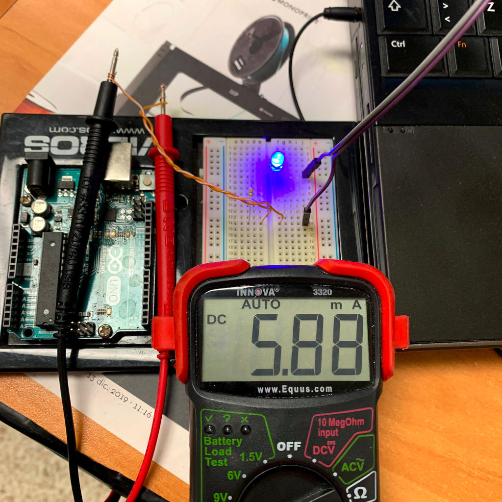
The blue led draws 5,88 mA of current.
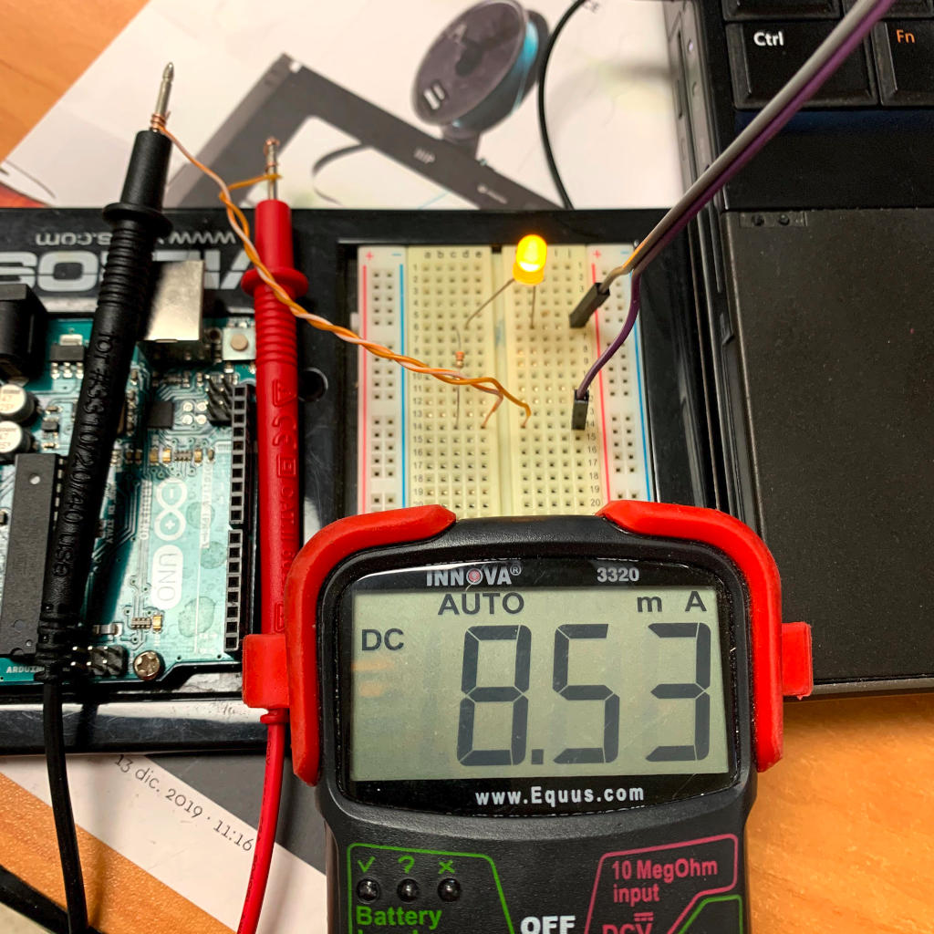
The yellow led draws 8,53 mA of current.
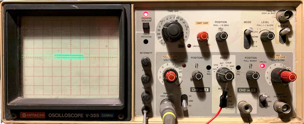
We used an old oscilloscope for this test. It is a Hitachi V-355.
This oscilloscope needs to be calibrated before using. This includes:
Adjust intensity
Adjust focus
Adjust illumintaion
Rotating the trace
Connect a probe to the calibration terminal (this model has a 0,5 V calibration wave)
Set Time/Div to 1 ms and Volts/Div to 0,5
Center the signal horizontally and vertically
Verify the wave is one unit tall and one unit wide
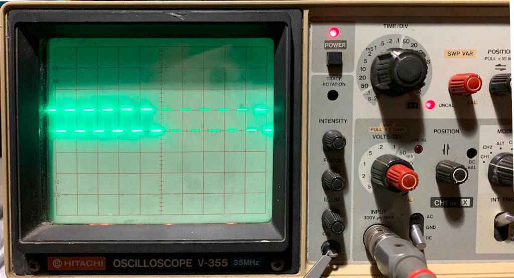
We uploaded a dimmer code to the microcontroller. This code dims in and out an led. This is done with pwm (pulse width modulation)
The pwm switches the supply voltage on and off quickly, variating the average power sent to the led. This gives the appearance of dimming.
It can be seen that as the lower line of voltage (0 V) gets bigger, the led dims out. As the upper line grows, the led shines brighter.