Exercise 8. 💻 Embedded Programming 📝 🤔 🙄
At the end of this exercise, I should be able to:
1. Compare the performance and the workflow for different microcontroller families.
2. Read and understand some information in data sheet for the microcontroller I am programming.
3. Program the board that I have made in exercise 6. Electronics Design with as many different programming languages and programming environment.
Compare performance and development workflows for microcontrollers (Group assignment)
This is a group assignment
The details of the steps can seen HERE.
Personal reflections:
1. I have to read more on the electronics. Many jargons, abbreviations, terminologies, and functions I still do not understand. I plan to do this over the weekend because my final project requires many electronics.
2. The use of oscilloscope to check the performance of the microcontroller is essential, but it is only useful once I understand how the microcontroller works and programmed.
Read a microcontroller data sheet🧐🤓😎
Attiny45 microcontroller is a high-performance, low power microchip 8-bit AVR RISC-based. The datasheet can be downloaded HERE.
The data sheet is 234 pages long and I will explain the features/information that are important based on my understanding.
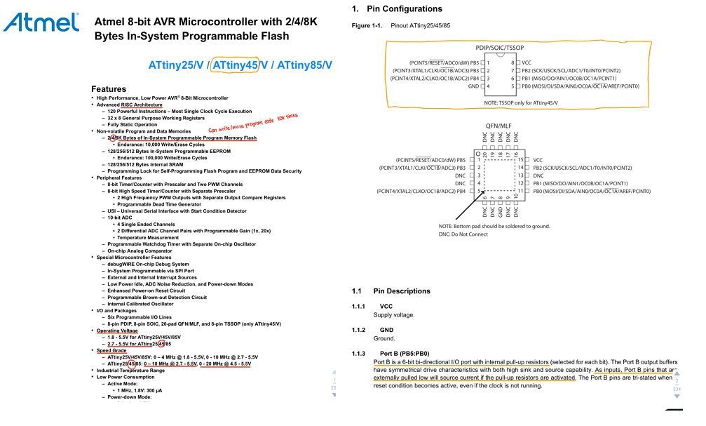 The first page contains the features of the microcontroller and page 2 contains the pin configurations. These information are important so that I can know the types of memory, the operating voltage, the speed etc. The pin configuration is important so that I can tell physically the location and label of each of the pin and later to read the functions/capability of each pin.
 By reading the block diagram, we could understand the roughly how the microcontroller works by looking at the flow of processes. Besides that It’s important to know the RESET pin and how it can be triggered. The erase/write cycle of the memory is also important. ATtiny 45 has 4K bytes of ISP Flash and can be written/erased up to 10k times.
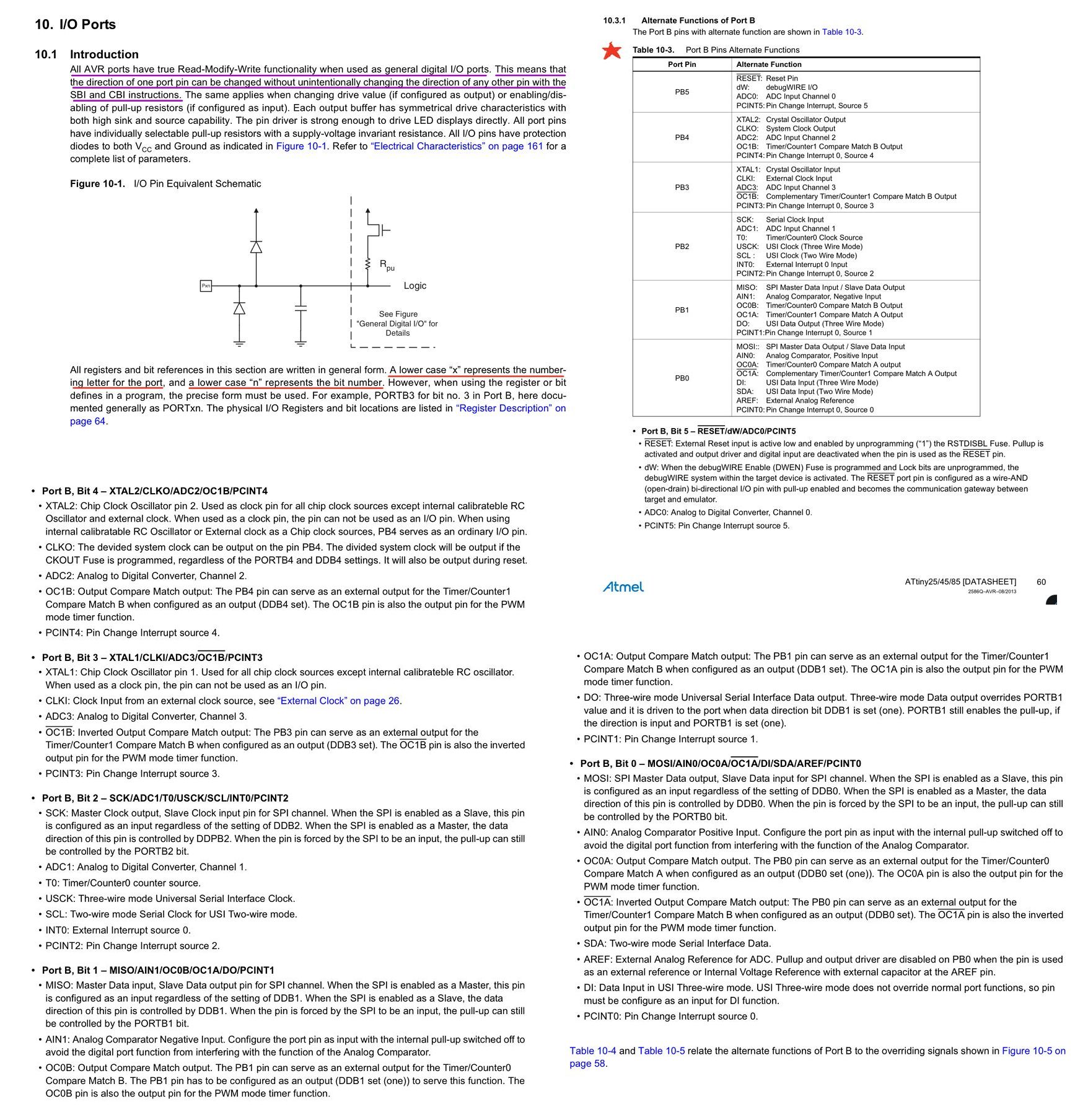 Subsection 10 contains the description of I/O ports and their capability and how it can be used for program. Example PB1 (PORT B, Bit 1) where I used as LED in my BLINK code is configured as MISO.
Program board to do something with as many different programming languages and programming environments👀🤓
For this exercise, I will program my ATtiny45 echo board that I built in week 6 using the ISP programmer I made in week 4.
The programming environments that I will use are:
1. ARDUINO IDE to compile and upload/install, and
2.Text editor, avr-gcc compiler and avrdude to upload/install.
While the programming languages that I will use are:
1. ARDUINO sketch (arduino code language) and
2. C programming.
A. Blink an LED using sketch in Arduino IDE:💯
1. I program the LED (blink) to on for 1 sec and off for 1 sec and repeat. This is the same as the week 6 exercise when I modified the original “blink” code in ARDUINO IDE.
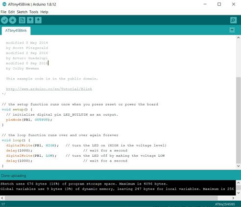
Below are the programming file and the video when the program is running.
2. I program the LED (blink) to on for 1 sec and off for 5 sec and repeat. The only change in the code is highlighted in yellow in the below picture.
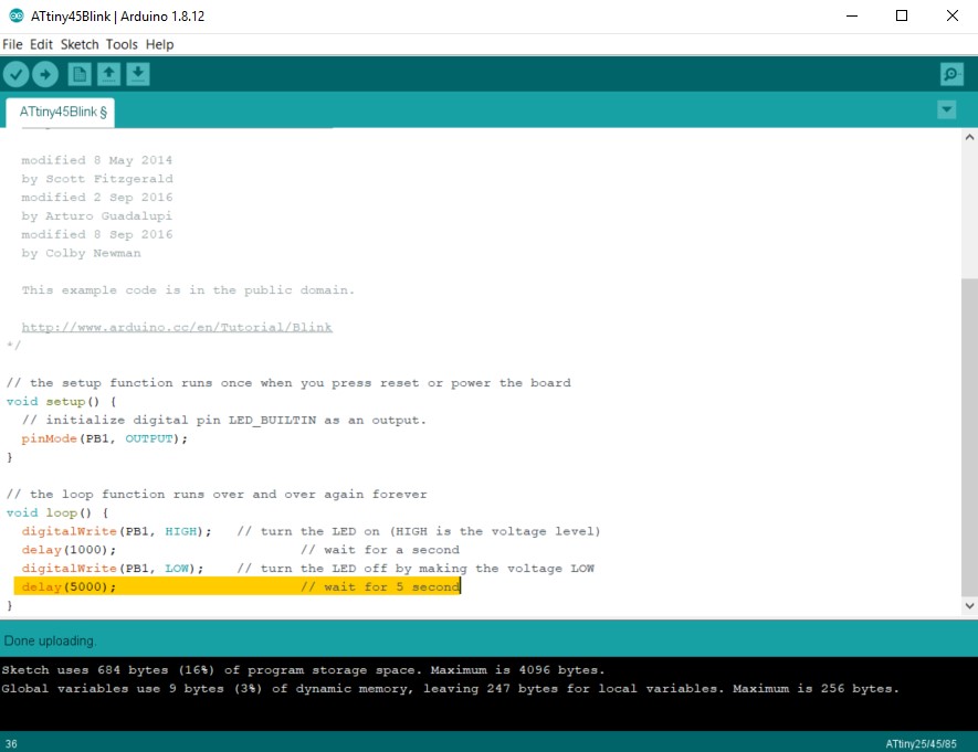
Below are the programming file and the video when the program is running.
B. Blink an LED with C programming language in Arduino IDE:💯
This is my first time coding using C/C++ programming hence I read tutorials and watch videos on this topic such as:
https://newbiehack.com/MicrocontrollerLEDblink.aspx
1. I program the LED to on for 1 sec and off for 1 sec and repeat.
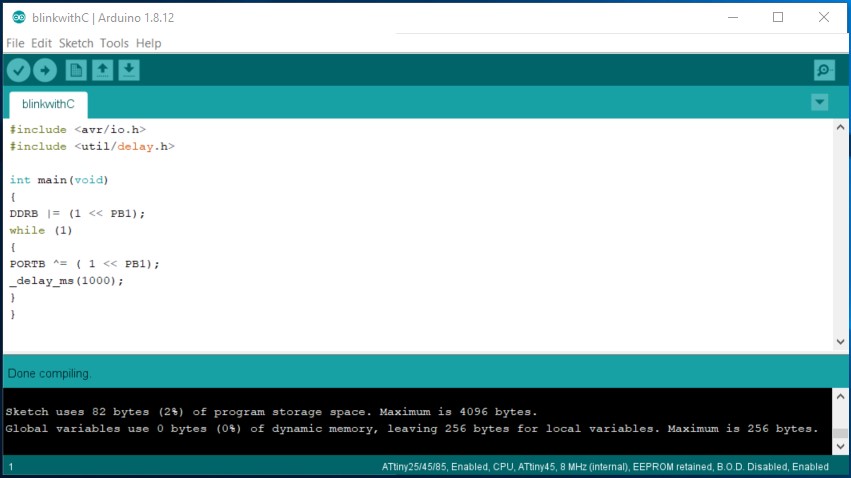
Below are the programming file and the video when the program is running.
2. I program the LED (blink) to on for 1 sec and off for 5 sec and repeat. The only change in the code is DELAY TIME
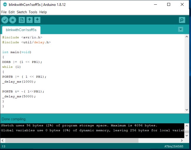
Below are the programming file and the video when the program is running.
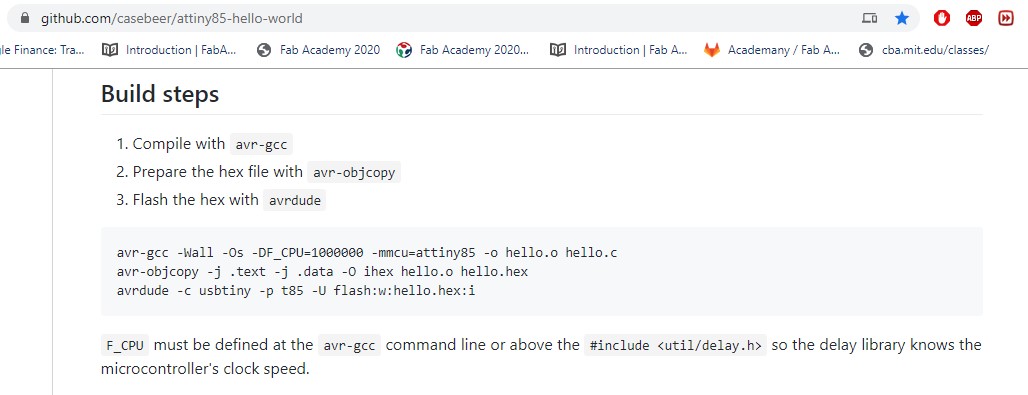
C. Blink an LED with C programming language in text editor (notepad) with avr-gcc compiler and avrdude to install the program.💯
I followed the instruction in this tutorial on how to use avr-gcc compiler and avrdude uploader and change the necessary parts, example the file name, the attiny model number etc.
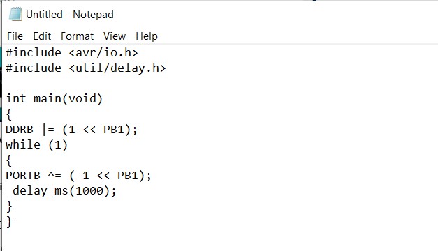
1. I program the LED to on for 1 sec and off for 1 sec and repeat.
Open notepad and type the C program for blink as shown below
 Save the file as blink.c in any directory and remember that directory. In my case it is C>Users>common>fabacademy>fts_firmware
Now, there’s a C source file with the name blink in that directory.
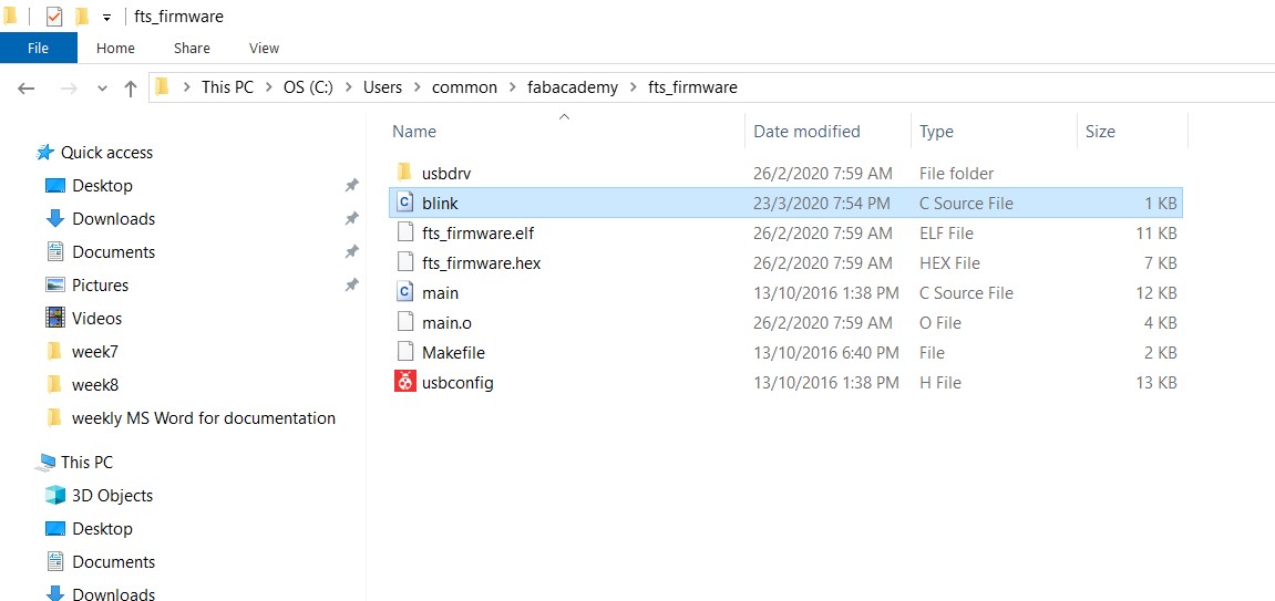 Open command prompt and change the directory to the same as your blink.c.
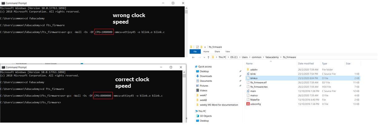
Compile with avr-gcc by typing the below command:
avr-gcc -Wall -Os -DF_CPU=1000000 -mmcu=attiny45 -o blink.o blink.c
I typed the clock speed to be 1MHz (-DF_CPU=1000000) which is wrong.
The implication of this is that the LED will blink at different timing, i.e. much faster than 1000 ms (1 second). We will see this in the next 2 videos.
I should type 8MHz, same as what I defined in the ARDUINO IDE. Hence the CORRECT COMMAND:
avr-gcc -Wall -Os -DF_CPU=8000000 -mmcu=attiny45 -o blink.o blink.c
This command will create blink.o in the same directory.
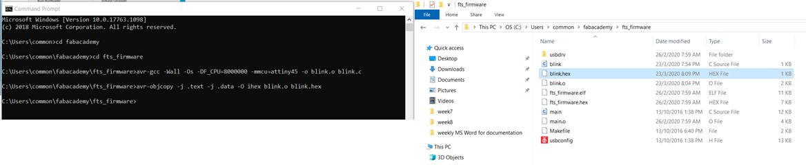
 Now prepare the hex file with avr-objcopy by typing the below command:
avr-objcopy -j .text -j .data -O ihex blink.o blink.hex
This will create blink.hex file in the same directory.
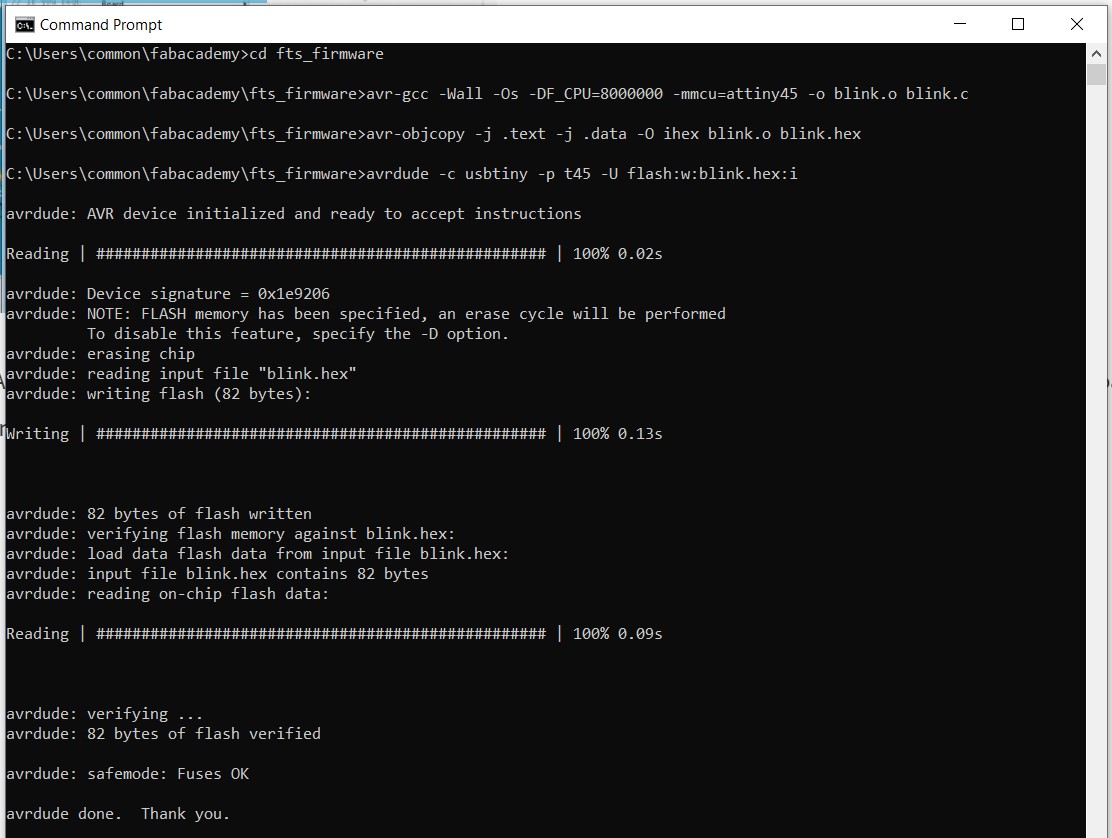
Finally, we will flash blink.hex with avrdude by typing the below command
avrdude -c usbtiny -p t45 -U flash:w:blink.hex:i
Below is the programming file
Below is the video of the wrong clock speed
Below is the video of the correct clock speed
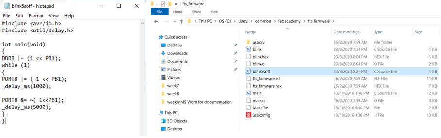
2. I program the LED to on for 1 sec and off for 5sec and repeat.
Open notepad and type the C program for as shown below. Save the file as blink5soff.c in any directory.
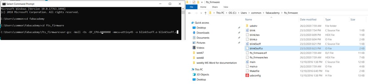
 Open command prompt and change the directory to the same as your blink5soff.c.
Compile with avr-gcc by typing the below command:
avr-gcc -Wall -Os -DF_CPU=8000000 -mmcu=attiny45 -o blink5soff.o blink5soff.c
This command will create blink5soff.o in the same directory.
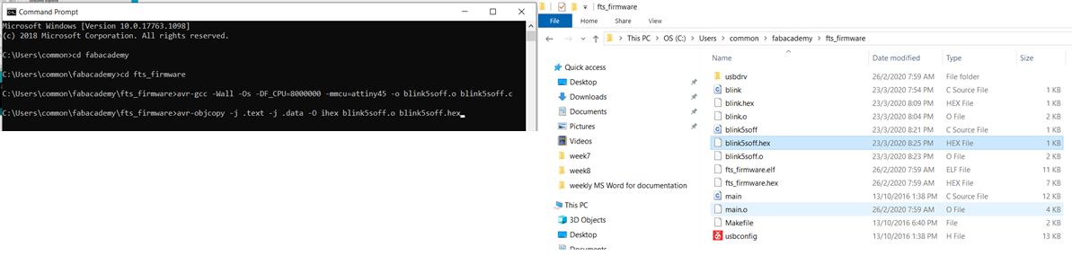
 Now prepare the hex file with avr-objcopy by typing the below command:
avr-objcopy -j .text -j .data -O ihex blink5soff.o blink5soff.hex
This will create blink5soff.hex file in the same directory.
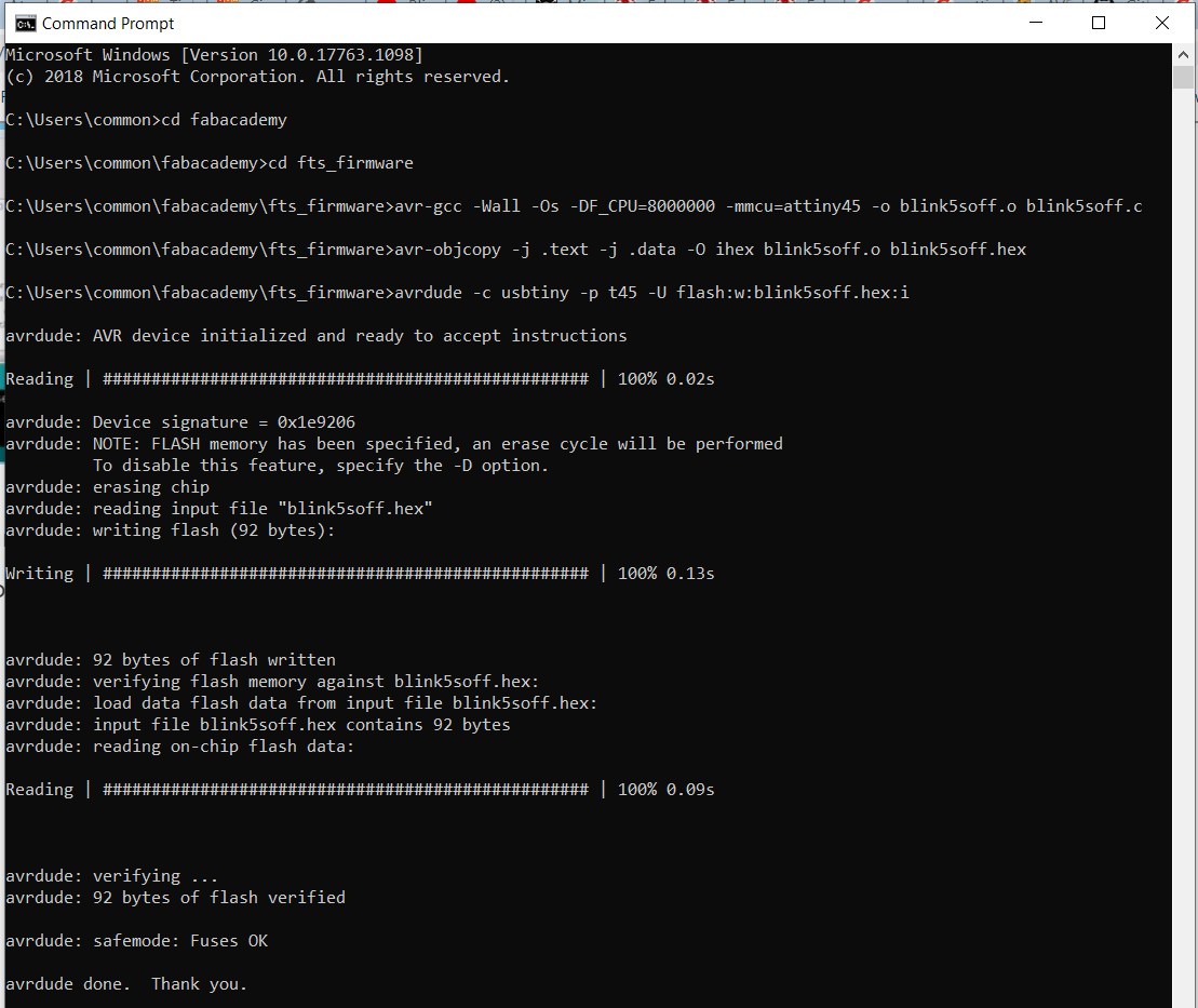
Finally, we will flash blink5soff.hex with avrdude by typing the below command
avrdude -c usbtiny -p t45 -U flash:w:blink5soff.hex:i
Below is the programming file
Below is the video when the program is running
D. Blink and LED using tinkercad to create Arduino sketch program.💯
For this, I followed this video tutorial tutorial on how to use tinkercad to create the program to blink an LED.
The programme is the same as part B, hence I won’t include the code nor the video. I will only explain the workflow below:
How to start using tinkercad:
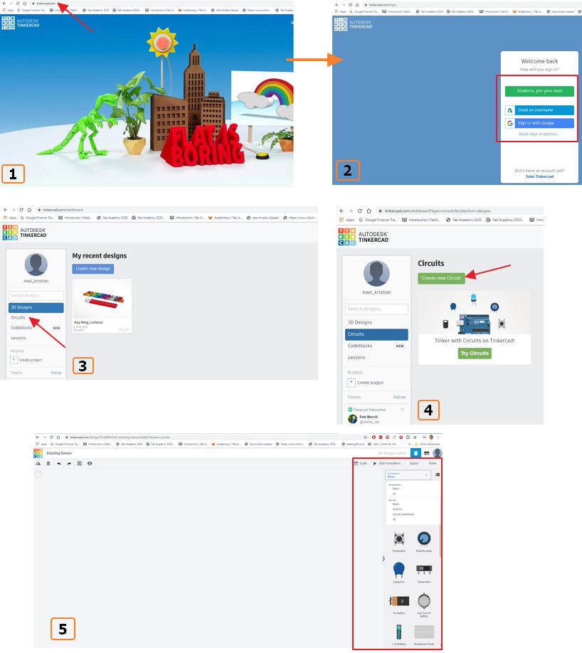 How to start making circuit design and simulation:
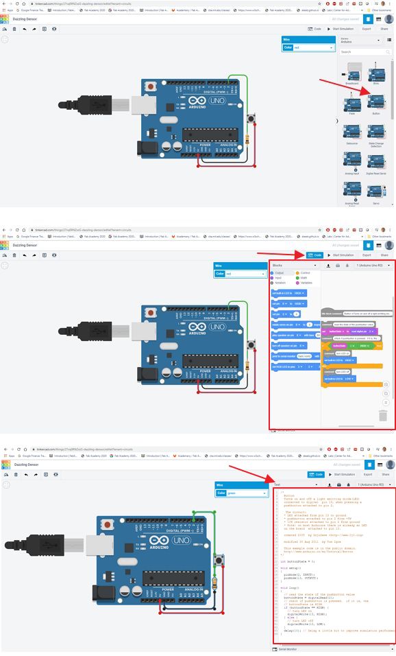 At the end, the sketch code can be downloaded to local and modify according to my own configuration on the ATtiny 45 board, example instead of the onboard LED on Arduino, I used PB1 as the LED output.