Exercise 7. 💻 Computer-Controlled Machining 🛠 🧤 👓 💪
At then end of this exercise, I should be able to:
1. Test speed, feed and toolpaths for CNC machine.
2. Demonstrate and document 2D design development (using Fusion360 to VCarve Pro) for CNC production.
3. Describe and document the workflow in CNC production.
4. Make (Design + Mill + Assemble) something big.
Test speeds, feeds, and toolpaths for CNC machine (Group assignment)
This is a group assignment.
The details of the steps can seen HERE.
Personal reflections in operating the CNC machine
1. Always ask if unsure. Safety is very important in this context because of the severity of the consequences. Always wear safety googles. Ensure there’s no hanging accessories, like necklace, watch, etc. Wear muffle when the spindle start to rotate and milling start.
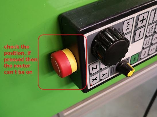
2. Always check that the emergency reset button on the manual handtool is not pressed. When it is pressed, the router can’t be switched on.
3. Observe the cutting result of previous user and check the condition of the end-mill before turning anything on. In our case, one edge of the end-mill was chipped off hence the milling result by the previous user was not smooth. Then ask the person-in-charge to help and assist in changing the end-mill.
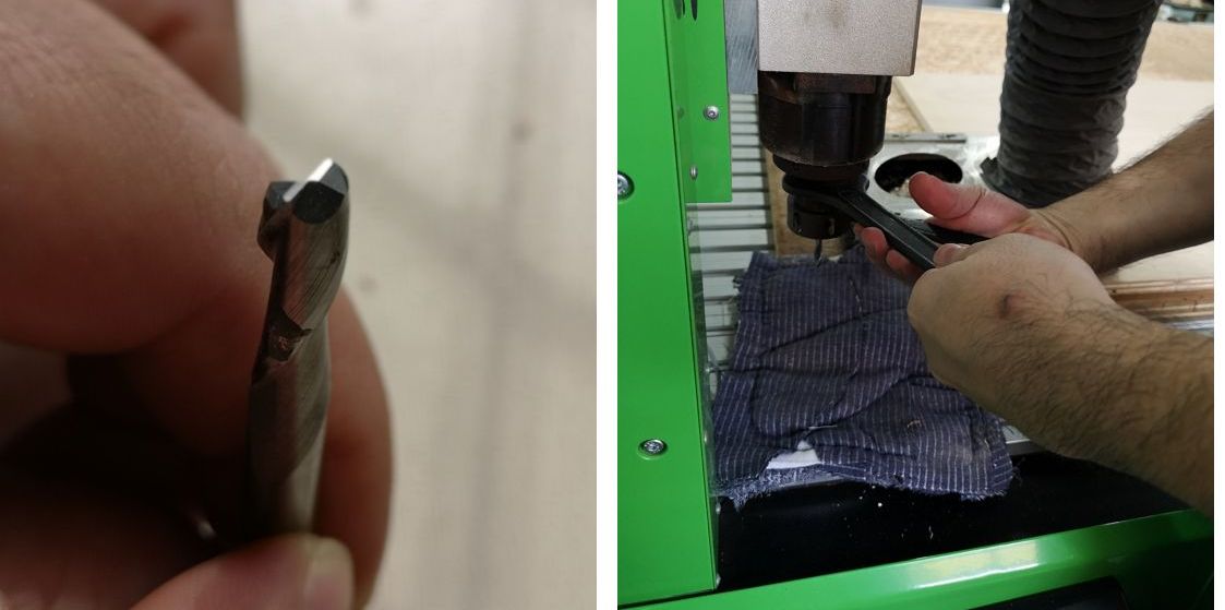
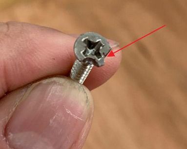
4. Calibrate the X, Y, Z position carefully. We did a mistake where the Y position was too near the edge hence the end-mill cut the screw on the wooden board.
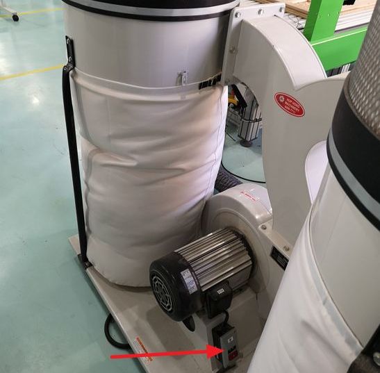
5. Turn-on the vacuum pump/dust collector once the spindle start to rotate. I forgot to on the vacuum pump/dust collector twice.
Make (design+mill+assemble) something big🕶⛑💪
Below are the processes that I went through to make "something big":
1. Designing in 3D and then 2D using CAD (Fusion 360).
2. Generating G-Code using CAM (VCarve Pro).
3. Milling using the CNC Machine.
4. Finishing and assembling.
1. Designing in 3D and 2D using Fusion 360
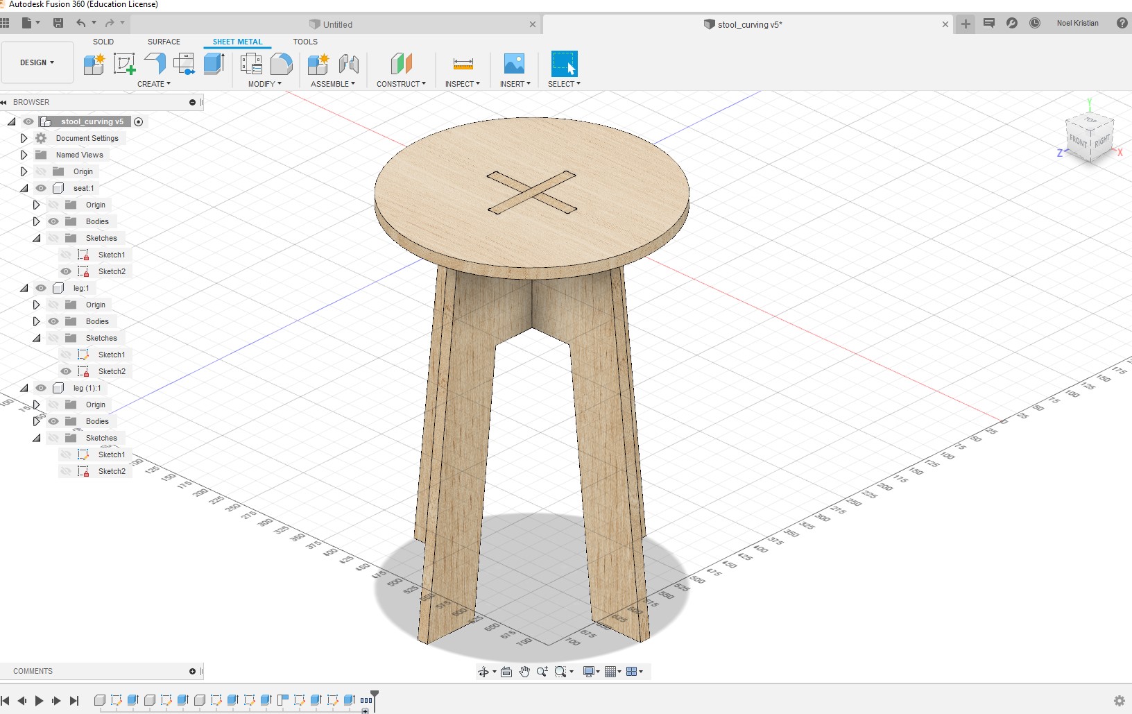
For this exercise I want to make a simple stool and followed the tutorial using Fusion 360. I had lots of difficulties in using Fusion 360 this time because I updated into the latest version but the old version can’t be uninstalled. Both version exist in my PC and somehow when I used the old version, often my sketches disappear. Hence I remove all the old version shortcut, so that I only have the latest version shortcut on my desktop.
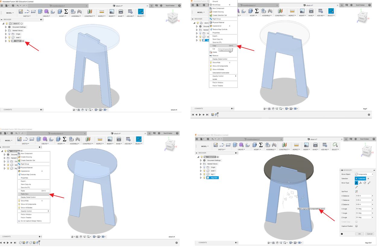
A new trick I learnt in Fusion 360 this time is the copying the entire component to make new component that is exactly the same but at the different coordinate. Shown below.
Right click and select copy. Select the stool v1 and right click and select “paste new”. Then rotate 90.
 Final result
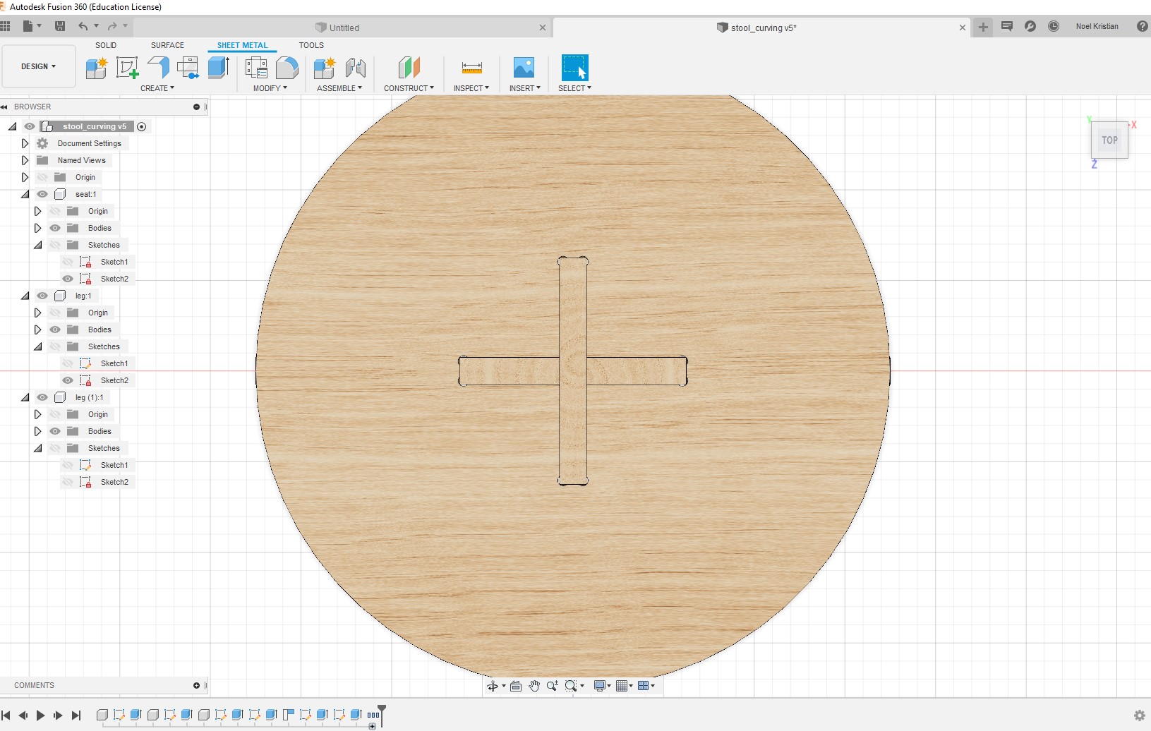
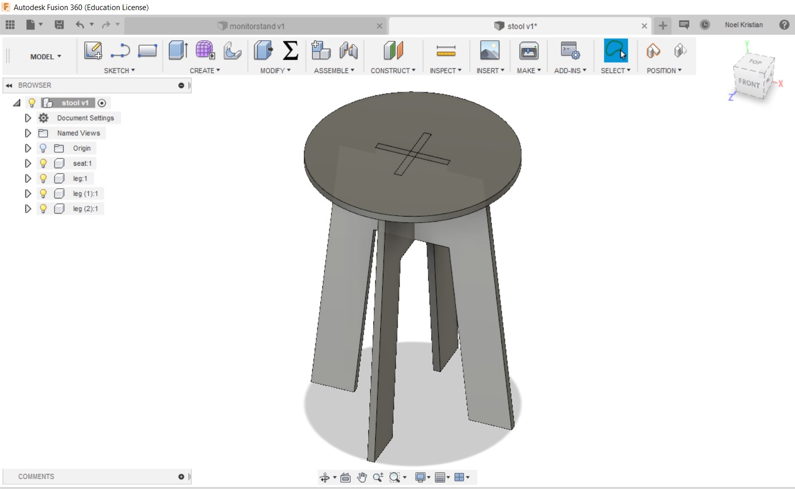 After creating the slot-in on the seat and changing the appearance of the body:
 Adding the dogbone so that for tight-fit joint, the end-mill can cut the entire part. The importance of dogbone and how to add it can be seen in this tutorial.
Download drawing files👇
2. Generating G-Code using VcarvePro
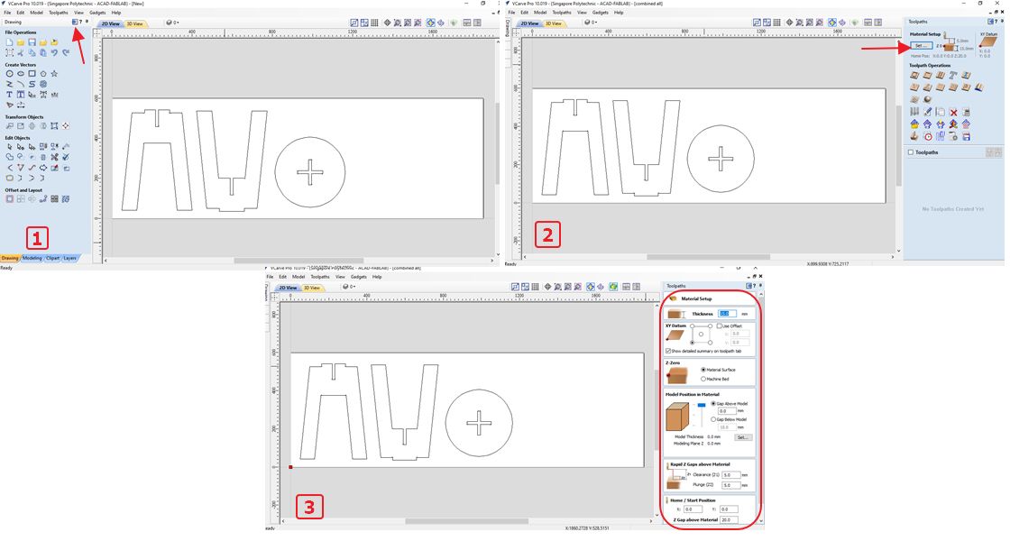
Specify the dimension of the wood stock that I will be using: Width (X)=1850mm, Height (Y)=600mm, Thickness (Z)=15mm in the Job size.
Job type: Single sided.
Z Zero position : Material surface.
 Open another Vcarve pro and this time select "open an existing file" and select the first sketch which is "seat.dxf".
Highlight the entire drawing lines and copy, paste to the first Vcarve pro drawing.
After pasting, move the profile drawing lines on to the board layout.
Repeat the same steps for leg1.dxf and leg2.dxf.
Arrange the 3 drawings nicely onto the board, not to near the edge.
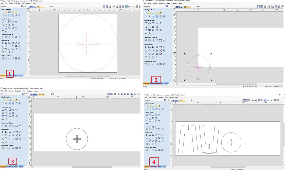 Highlight the entire drawing profile and copy, paste to the first Vcarve drawing.
Switch to toolpath command and set the material setup.
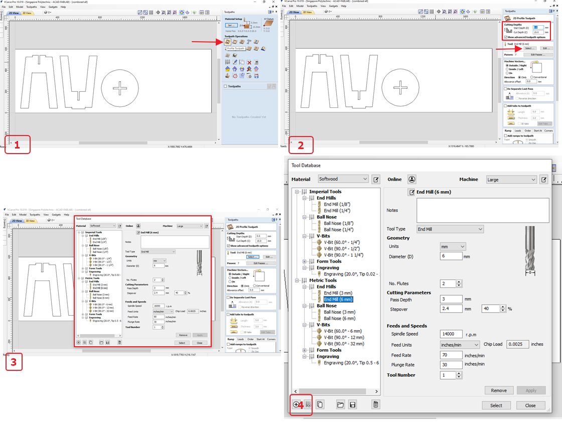
 Select "profile toolpath" because I want to mill all the way to cut the components.
If I want to just mill a pocket, I will select "pocket toolpath".
In the "profile toolpath" menu, let’s specify the cutting depth to be: Start depth = 0.0mm and Cut depth = 15.0 mm.
The cut depth is equal to the thickness of the material (wood) we are cutting.
Next is to select the end mill tool. These are the end- mill tool and settings I used.
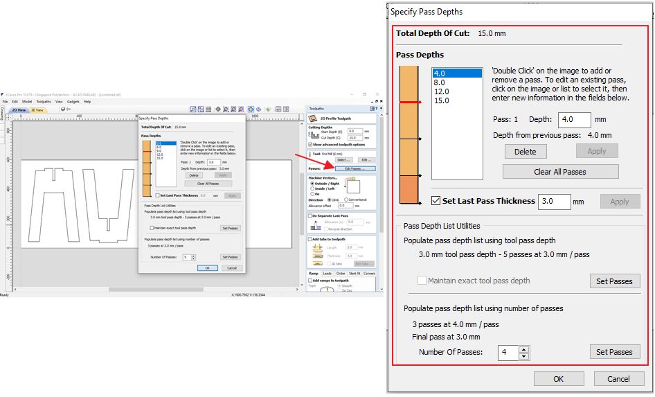
 Next is to “edit passes” and set the pass.
It is recommended to use a whole number for the each deep. And to use cut depth shorter than the end mill diameter. In this case shorter than 6mm.
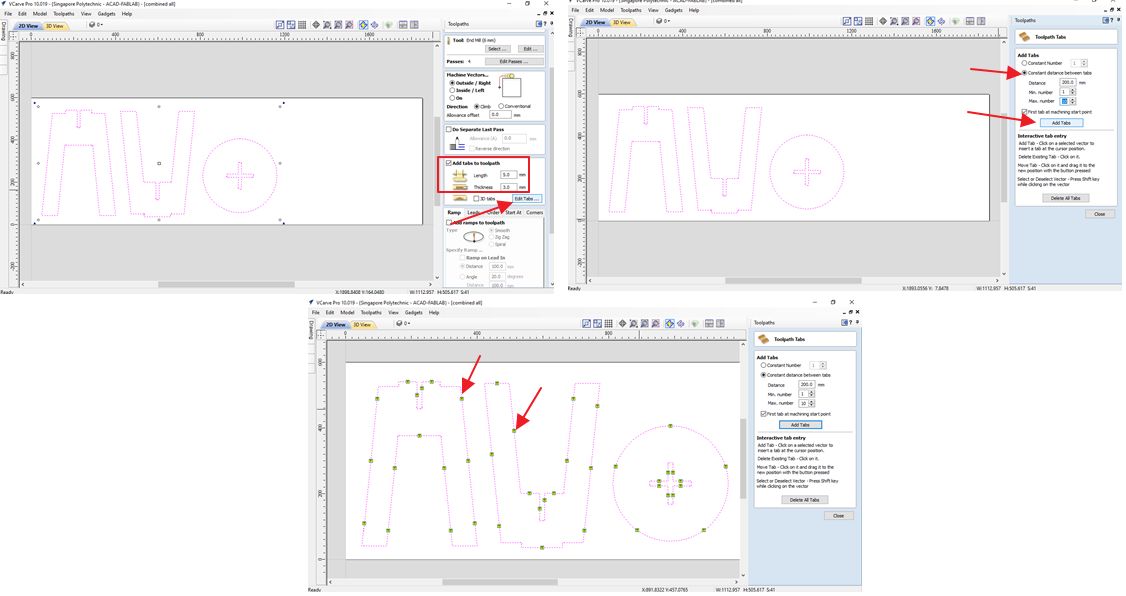
Next is to add tab, first highlight the entire profile drawing and then ticked the "add tabs to toolpath" and then click "edit tabs".
Manually move, delete and add in new tab onto the profile drawing.
Never put tab on the corner. On smaller cut off piece try to add in 2 tabs so that it won't fly out from the board.
 VERY IMPORTANT to check the vectors.
For a single component drawings, the vectors must be joint into a single vector.
In picture 1, I have multiple vectors on a single component as shown in the non-continuous purple line on the leg1 component.
I must combine the vectors that make up a single component into a single vector by joining all the vector by selecting "joint-joint open vectors".
Repeat for "leg2" and then repeat again for the "seat".
All open vectors are joined and the previous steps, namely cutting depth, tool: end mill (6mm) setting the end-mill, "edit passes", add "tabs" to toolpath, and ready to calculate toolpath.
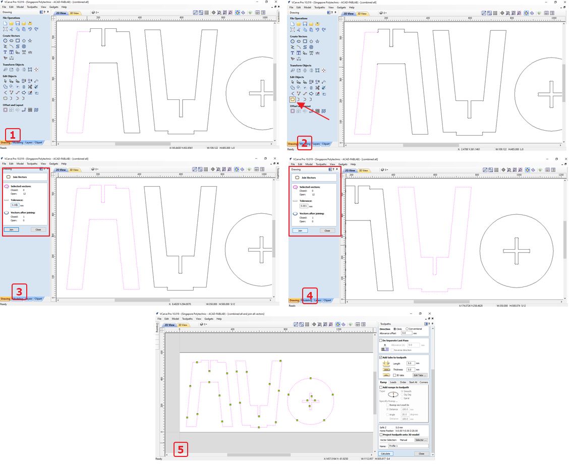 Ready to generate toolpath.
Before that, need to preview the toolpath.
After generating the toolpath, now I can save the generated toolpath as .tap
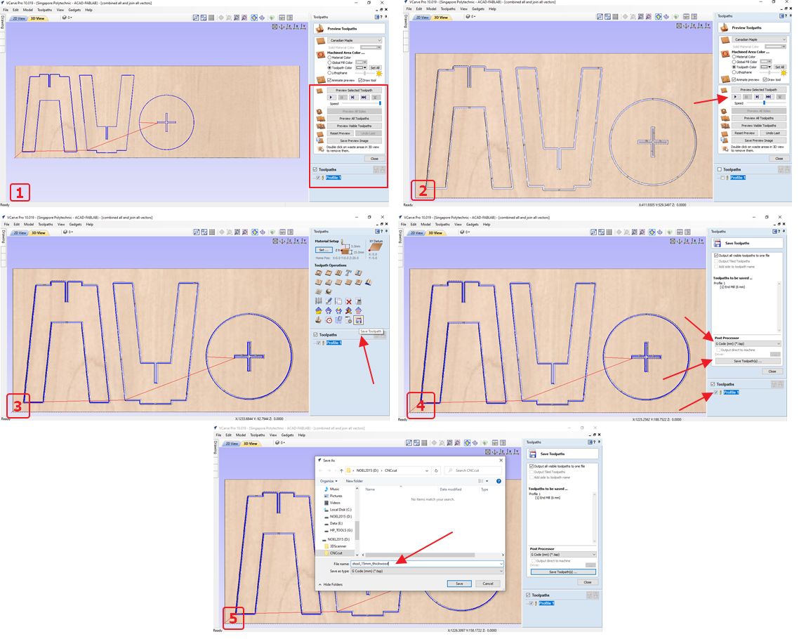
Download VCarvePro file and toolpath (G-code)👇
3. Milling using CNC VERSATIL machine⚠👓⛑
Ready to open the toolpath in the CNC router software, NC-EAS(Y) Pro software and set the VERSATIL CNC machine.
Open the g-code file that was generated in VCarve Pro.
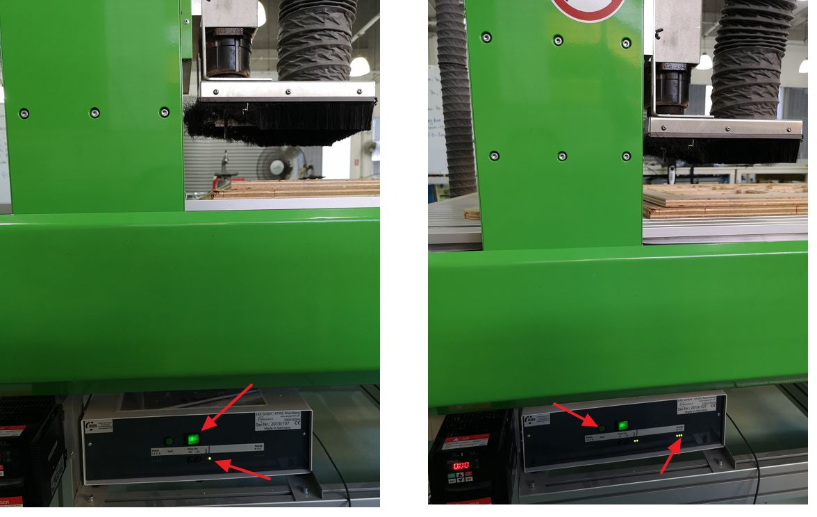
 And then on the CNC machine by pressing the on button then the green led is on and followed by the start button hence the ready X Y Z LED will blink once.
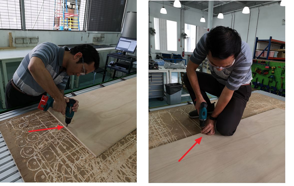
 Secure the stock wood on the sacrificial board using screws.
First is to secure on one of the end side. Observe the flatness of the wood, if curving upward or downward, start putting the screws from the area on the edge where the wood curve the most.
In this picture, the wood curved outward the most on that side hence I screwed that part.
 After that, must calibrate the X, Y and Z position of spindle by following these steps:
1. select "reference move".
2. tick the X, Y, and Z and then press OK. The spindle will move to it's default X, Y and Z. After this step then we can calibrate the X, Y, and Z.
3. To calibrate the Z- axis, select "tool measure" followed with OK and quickly move the Z height sensor below the spindle as shown in the picture below.
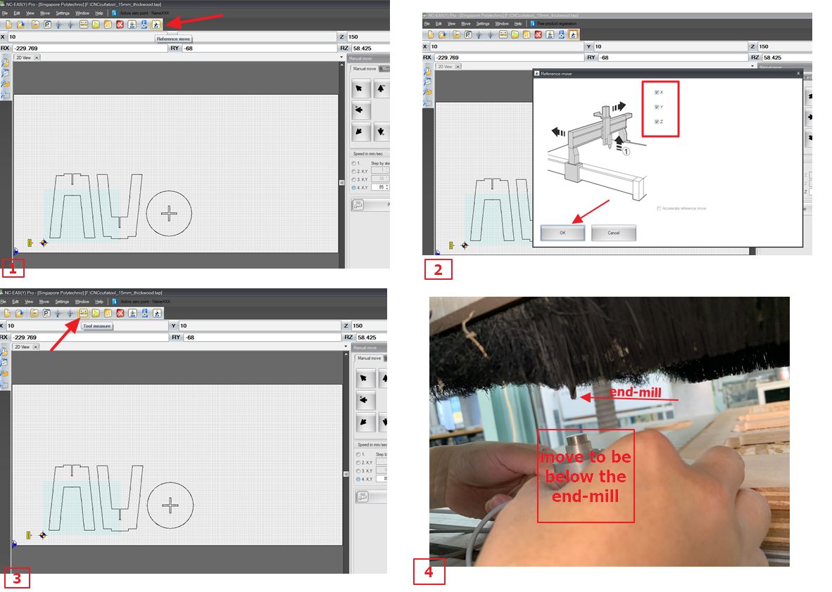 To calibrate the X, Y, we need to use the manual tool and adjust manually.
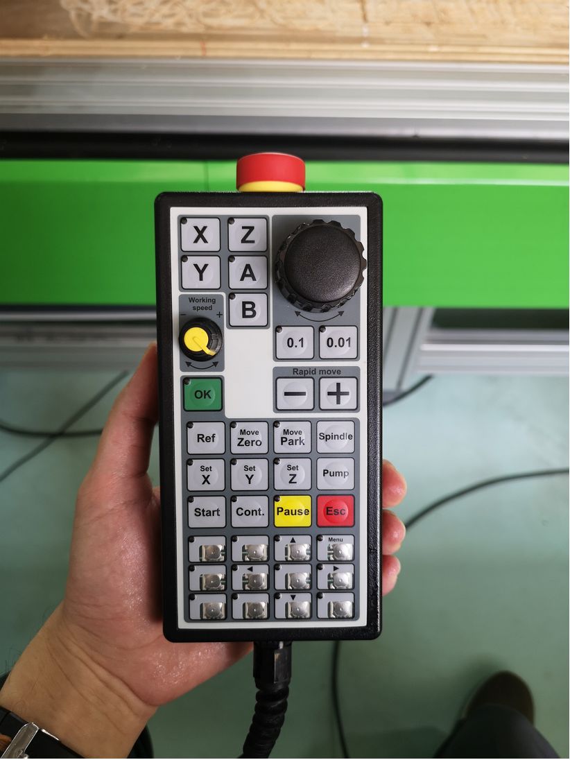 It is always good to manually move the spindle to the corner of the stock wood to ensure that the profile that I want to cut is within the dimension of the stock wood.
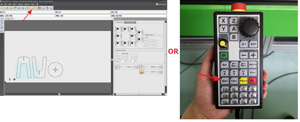
After the calibration is done, then I can start the milling by EITHER selecting "milling/drilling"in the software or by pressing start in the manual hand tool.
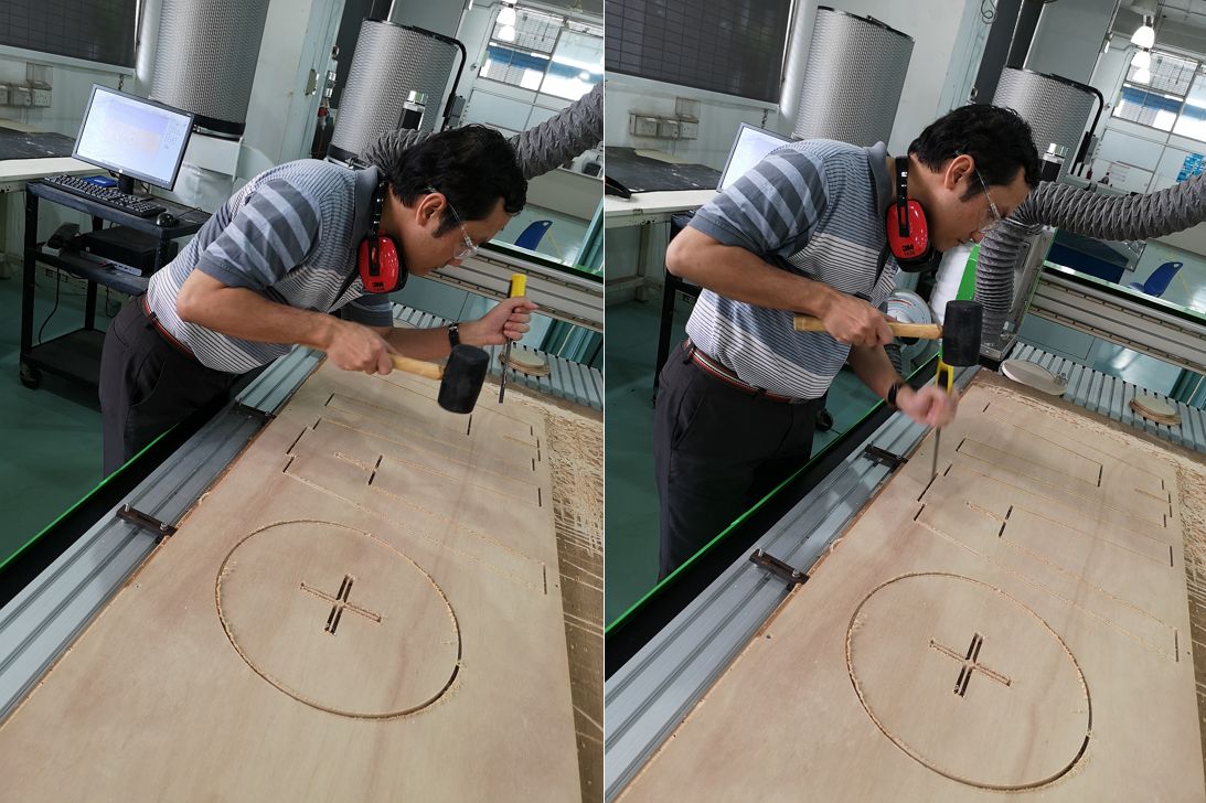
 When the milling has completed, I use chisel and mallet to remove the tabs. Must remove the tabs from the edge where we want to cut off the pieces to minimize the post-milling work such as filling.
4. Finishing and Assembling⚠👓
Next is to do the post-milling work and the stool is ready to be assemble.
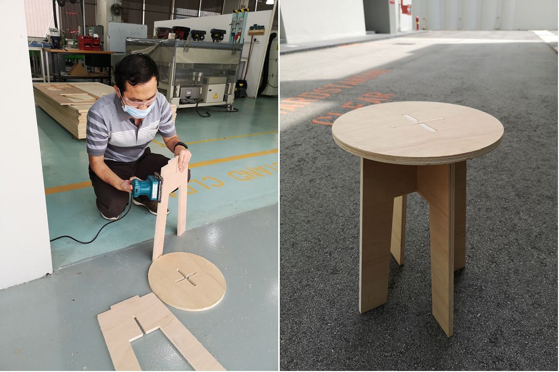 Testing the stool and it feels steady and I feel accomplished.🙂
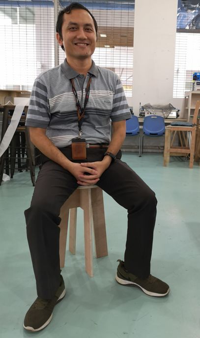 After gaining confidence, I want to make a monitor and laptop stand.
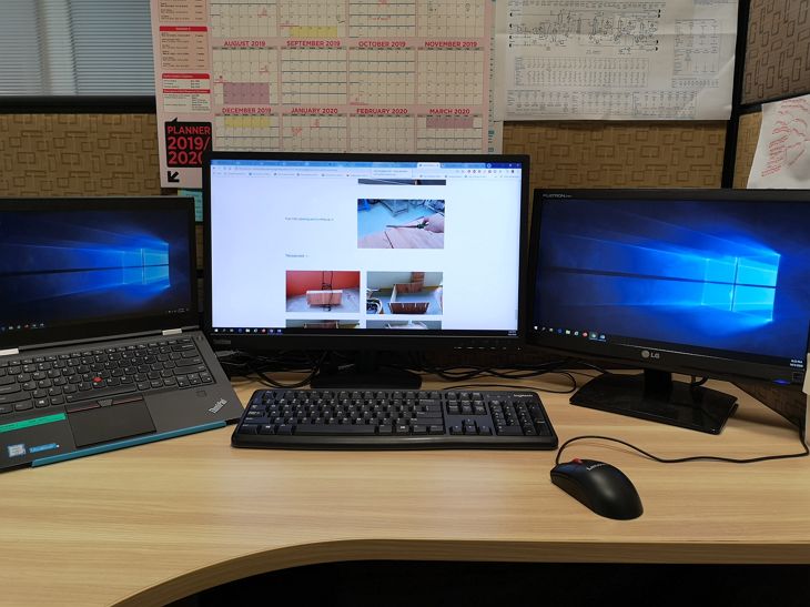
Below is the current configuration of my monitors and laptop.
It is not that ergonomics, hence a monitor stand will make my working position more ergonomic.
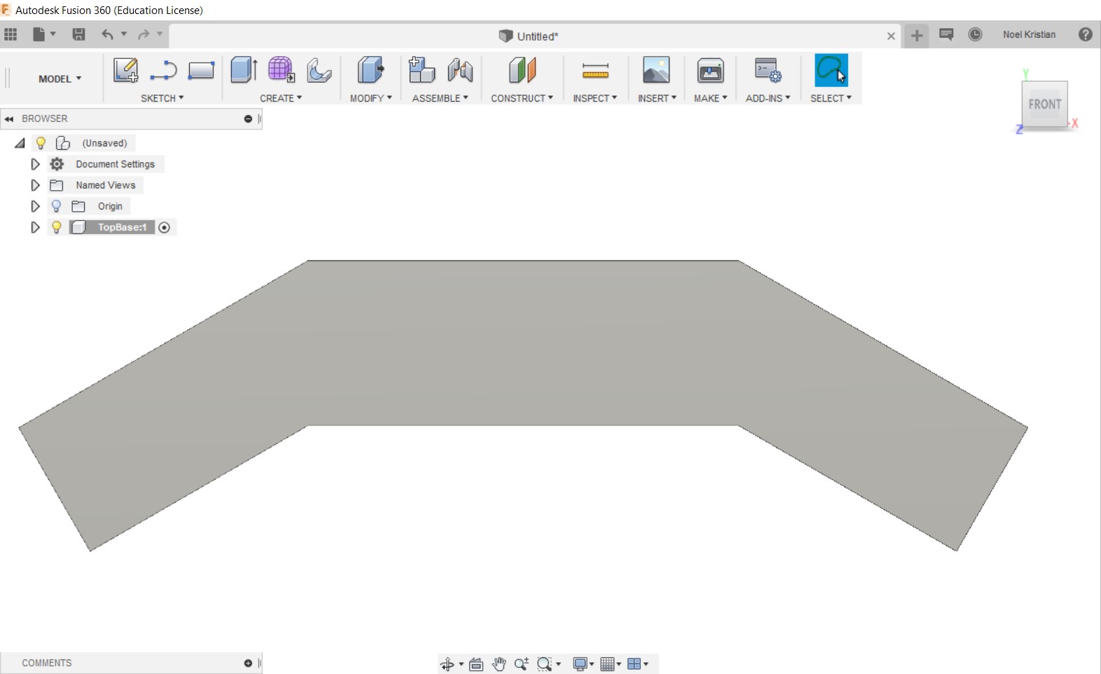
But I will be moving to a new office where I don’t know the furniture dimension and configuration, hence I will complete the design and assemble it after moving to the new office.
